Dedicated Micros DV-IP HD Operating instructions

draft
DV-IP HD
Installation and
Operation Guide

draft
Dedicated Micros ©2008
2
DV-IP HD
Whilst every attempt is made to ensure these manuals are accurate and current, Dedicated Micros reserve the right to alter or
modify the specication of the machine described herein without prejudice.
Contents
Installing the Unit ..............................................................................................7
Installation ......................................................................................................10
Remote Control ..............................................................................................12
Installing the DV-IP HD Unit............................................................................15
Conguring the Unit .......................................................................................24
Navigating The Menus ....................................................................................25
System Settings ..............................................................................................26
Time and Date ................................................................................................31
Serial Ports .....................................................................................................32
Audio ..............................................................................................................33
Features .........................................................................................................34
Maintain ..........................................................................................................36
Console Settings ............................................................................................37
Display ............................................................................................................41
Camera Settings .............................................................................................46
Record Settings ..............................................................................................49
Alarm Settings ...................................................................................................... 57
Zone Actions ...................................................................................................61
Network Settings ............................................................................................66
Analytics & Text ..............................................................................................76
Archive ............................................................................................................78
Oracle Conguration .......................................................................................79
Using the IR Remote Control ........................................................................100
Appendix A ....................................................................................................105
Appendix B ...................................................................................................106
Appendix C ...................................................................................................108

draft
Dedicated Micros ©2008 3
DV-IP HD
Introduction
What is the…
DV-IP HD ?
A comprehensive digital recording solution, the DV-IP HD is a stand-alone high-performance
recording system offering reliable, networked, scalable CCTV with High Denition recording
capabilities at an affordable price.
The DV-IP HD is the ideal companion to the DM CamVu 2000, allowing multiple megapixel video
streams to be viewed and recorded simultaneously in high denition.
Ideal for installations were high record rates and network capabilities are required.The DV-IP HD
offers JPEG or MPEG-4 recording at scalable quality settings and global record rates of up to
200pps at 4CIF resolution.
Dedicated Micros renowned MultiMode record feature enables an operator to set different recording
rates, resolution and compression formats across scheduled, normal and alarm modes for each
individual camera.
Available with 8 camera inputs, all offering telemetry control, the DV-IP HD has built in Alarm
functionality and onboard Activity detection software.
To give operators maximum viewing exibility, the DV-IP HD can be congured to contain a mixture
of spot or main monitor outputs. Camera channels can be viewed in single or multi-screen mode on
a local monitor or remotely over an IP connection.
The accompanying Infra-Red (IR) Remote Control has a colour coded ‘Softkey’ interface with
conguration menus common to both local monitor and web interface, making for easy set-up and
operation.
Dedicated Micros trademark plug and play intuitive set-up and user-friendly interface helps keep
installation and operator training to a minimum.
The DV-IP HD includes as standard internal storage with expansion available via external high-
speed SATA ports. A DVD-R Writer and USB ports are provided for external video archiving.
The unit also offers integrated text support, allowing users to connect with cash registers in retail
applications to monitor Point Of Sale (POS) locations. Capturing and associating video with the
relevant text information allows the operator to search video footage by time, event, and text data to
provide evidence of fraud or to aid identication of regular offenders.
Among the many other features included as standard on the DV-IP HD are; multiway display, picture
in picture viewing and remote monitoring using NetVu ObserVer (utilising DM’s unique TransCoding
capabilities to provide uent live and replay images).
With telemetry control of up to 16 cameras (including coax telemetry), control of dome cameras,
audio recording, activity detection plus many more exciting features, the DV-IP HD is the ideal
product when high-performance video recording and transmission is required at an affordable cost.
For further information, please visit the website:
www.dedicatedmicros.com
or contact customer services in your region.

draft
Dedicated Micros ©2008
4
DV-IP HD
Features
The DV-IP HD from Dedicated Micros is equipped with an array of valuable features designed to
enhance the operator experience.
• 8, camera inputs
• Up to 200pps at QCIF to 4CIF resolution
• Telemetry support (Coax & Serial)
• I.P Camera support
•Megapixel camera support
•HDMI monitor support
• Alarm Inputs & Outputs
• Two way network intercom
•Internal storage
• All DVR functions fully supported by Keyboard/IR Remote Control/Mouse
• Scalable recording settings
• MultiMode Recording - Dynamically-switchable resolution, record-rate & compression
(MPEG4/JPEG) per camera
• Built in activity detection
• Single, Picture in Picture and Multiway displays
• Live and playback viewing locally and over Ethernet
•Point&go telemetry control
• JPEG or MPEG-4 recording and transmission
• Web pages provide easy remote conguration
• Embedded NetVu Console functionality
• Easy to use on-screen, colour coded softkey menu options
• Text support and text search features ideal for retail installations
• Built in DVD-R writer and USB ports for download of video archive to external ash
memory and uploading software updates
• Optional external keyboard available
• Conguration via USB mouse and USB QWERTY keyboard
•BS8418 compliant
The DV-IP HD has NetVu Connected technology built-in to ensure maximum compatibility with future
developments in networked security. NetVu Connected technology enables the DV-IP HD to fully
interact with other NetVu Connected compatible products from DM including the DVIP Decoder,
NetVu ObserVer and PDA Viewers. Providing interoperability between the worlds leading security
companies, NetVu Connected uses industry standard networking protocols supported by a wide
range of third party integration products and SDKs to ensure future on-going compatibility.
COMMON CONFIGURATION INTERFACE
A Common Conguration interface is displayed when the unit’s conguration screens are accessed
locally at the unit or remotely via a web browser. This unied system ensures that the installer is
familiar with the conguration screens irrespective of their location to the unit, minimising training
and familiarisation time and increasing the speed of installation and alteration.

draft
Dedicated Micros ©2008 5
DV-IP HD
The DV-IP HD includes a unique colour-coded, soft key menu structure and onscreen Graphical
User Interface (GUI). Context sensitive, the menu structure always represents the area of the menu
the user is in, allowing them to quickly select the options and settings they need without having to
trawl through menu pages and options. The colour coded buttons displayed on the monitor match
those on the IR Remote Control, whilst control can also be conducted through an attached USB
Mouse or supported Keyboard (KBC1 / KBC2).
VIDEO TIMELINE
The Video Timeline feature is a new intuitive interface for the control and navigation of playback
video. With control via the IR Remote Control or supported Keyboard, the colour-coded on-screen
display matches the buttons on the Remote Control or Keyboard allowing the user to control the
video forward or backwards in incremental steps of seconds, minutes, hours, days and weeks.
MAPS
Users can now navigate around their CCTV installation using graphical maps. Selecting the relevant
camera from the map will instantly connect the user to that cameras image stream. With the ability
to load bespoke map images and oor plans to reect their installations, the Maps feature is ideal for
quickly identifying camera locations around a site or CCTV network.
Point&go provides the user with easy to use, fast, accurate telemetry control via an attached
monitor. With no need for a telemetry keyboard, users are able to use Pan & Tilt control of a
Dedicated Micros Oracle Dome simply by clicking an area of the monitor. The camera will instantly
respond, positioning the selected area in the middle of the screen, ideal for tracking movement
through a scene.
ePTZ
Dedicated Micros ePTZ uses an advanced image ‘interpolation’ algorithm that reveals detailed
information that simple pixel-stretching digital zoom commands cannot. Users can operate ePTZ as
they would Analogue Zoom - moving around the scene and zooming in / out using the IR Remote
Control or a supported Keyboard - even on static analogue cameras. Electronic Zoom can be
carried out on both live and playback video. Providing the ability to retrospectively control and view
an image, a great aid in post-event analysis.
Absolute Positioning
Using Camera Selection Maps and the unique Absolute Positioning capability of Dedicated Micros
Oracle Dome cameras, an operator can, with one mouse click, select a camera and send it to view
an area of the site (Pan and tilt). Absolute Positioning is ideal for following someone from camera to
camera around a site and greatly increases event response time, particularly for operators unfamiliar
with a site layout and camera location.
Design of the manual
For ease of use, this manual has three parts:
1. Installation Shows details of how to install the unit and connect external devices.
2. Conguration Shows details of the units menus.
3. Operation Shows quick reference details on how to control the unit.
The order and layout of these pages has been designed to help the setup process. It is recommended
that the menus are edited in sequential order to enable accurate, easy and efcient

draft
Dedicated Micros ©2008
6
DV-IP HD
Important Safeguards
Read Instructions
All the safety and operating instructions should be read before the unit is operated.
Power Sources
This unit should be operated only from the type of power source indicated on the manufacturer’s
label.
Servicing
Do not attempt to service this unit yourself as opening or removing covers may expose you to
dangerous voltage or other hazards.
Refer all servicing to qualied service personnel.
Ventilation
Ensure unit is properly ventilated to protect from overheating.
All the safety and operating instructions should be read before the unit is operated.
To prevent re or shock hazard, do not expose this equipment to rain or moisture. The lightning ash
with arrowhead symbol within an equilateral triangle is intended to alert the user of this equipment
that there are dangerous voltages within the enclosure which may be of sufcient magnitude to
constitute a risk of electric shock.
This is a class A product. In a domestic environment this product may cause radio interference in
which case the user may be required to take adequate measures.
Lightning Strike
The unit has some in-built protection for lightning strike, however it is recommended that isolation
transformers be tted to the system in areas where lightning is a common occurrence.
Regulatory Notes and FCC and DOC Information
(USA and Canadian Models Only)
Warning: This equipment has been tested and found to comply with the limits for a Class A digital
device, pursuant to part 15 of the FCC rules. These limits are designed to provide reasonable
protection against harmful interference when the equipment is operated in a commercial
environment. This equipment generates, uses, and can radiate radio frequency energy and, if not
installed and used in accordance with the instruction manual, may cause harmful interference to
radio communications. Operation of this equipment in a residential area is likely to cause harmful
interference in which case the user will be required to correct the interference at their own expense.
If necessary, the user should consult the dealer or an experienced radio/television technician for
corrective action. The user may nd the following booklet prepared by the Federal Communications
Commission helpful: “How to Identify and Resolve Radio-TV Interference Problems”.
This booklet is available from the US Government Printing Ofce, Washington, DC20402,
Stock No. 004-000-00345-4.
This reminder is provided to call the CCTV system installer’s attention to Art. 820-40 of the NEC that
provides guidelines for proper grounding and, in particular, species that the cable ground shall be
connected to the grounding system of the building, as close to the point of cable entry as practical.

draft
Dedicated Micros ©2008 7
DV-IP HD
CE Mark
If this product is marked with the CE symbol it indicates compliance with all applicable directives.
Directive 89/336/EEC.
A ‘Declaration of Conformity’ is held at Dedicated Micros Ltd.,
1200 Daresbury Park, Daresbury, Cheshire, WA4 4HS, UK.
Laser
The unit supports an integrated CD/DVD writer, the following are additional warnings associated with
installing and operating the CD/DVD writer, please pay particular attention to this information.
• Caution - Use of controls or adjustments or performance of procedures other than those
specied herein may result in hazardous radiation exposure.
• To prevent exposure to laser emanations (harmful to the eyes), do not attempt to
disassemble this unit.

draft
Dedicated Micros ©2008
8
DV-IP HD
Installing the Unit
Before you start
Check the contents of the box
Remove all items from the packaging and check the items listed below are present.
• DV-IP HD DVR
• IR Remote Control
• IR Remote Control Extender
• Mouse
• Power Leads
• DV-IP HD Software disc
If any of these items are missing, please contact Dedicated Micros Technical Support team.
Note: Before installing the DV-IP HD carefully read all Safety Instructions and the following
information on where the unit should be located.
Available Accessories
The following accessories can also used in conjunction with the DV-IP HD.
• KBC1 Keyboard
• KBC2 Keyboard
• Managed Storage Unit - Extend storage capacity to 5TB
• Managed Continous Archiving - Mirrored RAID1 storage unit
For further information about any of the above products, please contact Dedicated Micros customer
services in your region.
Choosing a location for installation
• The DV-IP HD is designed to be desk, shelf or rack mounted. Rack mounting brackets
are available as an optional accessory.
• Ensure the DV-IP HD unit is properly ventilated to protect from overheating.
• Ensure there is a 3cm gap on both sides of the unit.
•Ensure the IR receiver on the front of the unit faces the operator position, and is not
more than 3 metres (10 feet) from the operator. An IR Remote Control Extender is also
available.
• Ensure the unit is not located anywhere it could be subject to mechanical shocks.
• The unit should be located in an area with low humidity and a minimum of dust. Avoid
places like damp basements or loft spaces.
• If the unit is to be installed in a closed assembly, the maximum operating temperature
must not exceed 40°C (104°F).
• Ensure there is reliable earthing of the mains outlet when tted to supply connections
(other than direct connection to the branch circuit).
• Any branch circuit supplying the unit must be rated at 15Amps.
• It is recommended that an uninterrupted power source be connected to the unit in case
of power failure (to ensure continuous operation of the unit).

draft
Dedicated Micros ©2008 9
DV-IP HD
Electrical Connections
Please ensure the following are available and have been tested prior to the installation:
• Mains point
• Network point
• Network cable
• Active video signals i.e. at least one working camera feed
• PC with CD ROM drive and connection to the same network as the DV-IP HD unit
(Recommended).
Quick Overview of DV-IP HD Record Settings CONFIRM BELOW INFO IS CORRECT
DV-IP HD units provide out of the box:
High performance recording on ALL cameras with minimal conguration.
Consistent recording duration and smooth motion video per camera regardless of the number of
cameras.
Default record settings for ‘Normal’ variant units is MPEG4 5pps, jPEG 1pps or MultiMode
recording.
Default record settings for ‘Medium’ variant units is MPEG4 2pps, jPEG 0.5pps or MultiMode
recording.
Default 14 or 30 day storage capacity.
Complete Flexibility
The advanced record menu can be used to congure individual cameras to suit specic
requirements e.g. Entry/Exit routes. Various storage sizes are available dependant on the number of
cameras, the storage options and recording rate selected.
The picture quality can easily be increased if less than 14 days standard recording is required.
Note: It is the Installer/Owner’s responsibility to ensure that the record duration is set to the
necessary requirements of the application.
MultiMode Recording
The unit supports MultiMode recording which is a storage technology developed by Dedicated
Micros. This offers the ability to set different recording rates, resolutions and compression formats
across scheduled, normal and alarm modes for each individual camera.
By varying the quality, bit rate and le size of the recorded images, the MultiMode function can
increase recording capabilities of the unit.
MultiMode offers:
Ability to set different recording resolutions.
Ability to set and switch MPEG or JPEG compression recording as required.
Ability to set PPS recording rate per camera.
Dynamically switchable resolution when switching from Normal to Event recording.
Dynamically switchable compression between MPEG4 and JPEG from Normal to Event
recording.

draft
Dedicated Micros ©2008
10
DV-IP HD
Installation
Front Panel connections
Data
DVD-R Internal DVD-R drive (located under hinged ap)
USB USB2.0 connector (located under hinged ap)
Socket Can be used to connect an external IR receiver to replace the internal unit (located
under ip down lid)
LED’s Power - The Power LED will be green to indicate power is connected to the unit
HDD (Hard Disk Drive) - This will ash when images are being stored to the hard disk
Network - The Network LED will be green to indicate a connection
Rear Panel connections
REARPANELDWGSERVER.EPS
Video
8. way unit
VID1 to VID8 75Ω BNC composite video input, 1V pk-pk with loop through
MON A 75Ω BNC composite monitor output, 1V pk-pk
MON B Spot Monitor output
MON A S Video Connection
HDMI 2x High-Denition Multimedia Interface connectiors
Audio
Audio IN (Dual) RCA (phono) socket, 8KHz/16KHz/22KHz sampling 75Ω input
impedance, 1V pk-pk
Audio OUT (Dual) RCA (phono) socket, line level <100Ω output impedance,1V pk-
pk amplication required

draft
Dedicated Micros ©2008 11
DV-IP HD
Data
SERIAL 1 RS-232 (3 wire & 9 wire)
SERIAL 2 RS-232 (3 wire & 9 wire)
SERIAL 3 (PTZ) RS-485 (2 wire & 4 wire)
SERIAL 4 (PTZ) RS-485 (2 wire & 4 wire)
USB 2x USB2.0 connectors
NET RJ45 Ethernet network connector, 10/100 Mb/s Ethernet Network
KBD RJ12 connector for use with Dedicated Micros telemetry
keyboards (KBC1, KBC2))
EXP RJ12 expansion port for future use
SATA 2x E-Sata port available for storage expansion
Power
POWER IEC mains power socket & switch
Alarms and relays
ALARMS IN Via 25-way (female) D Type 24V 200mA
17 general alarm inputs
Range of Alarm states are:
i. 0 – 800R = Short circuit
ii. 800R – 2K = closed contact
iii. 2k – 12k = open contact
iv. > 12K = open circuit
RELAYS Via 9-way (female) D Type rated at 24V 200mA
6 onboard light duty relay output (500mA@ 12V-48V Max)
draft
Dedicated Micros ©2008
12
DV-IP HD
Installing the DV-IP HD
This procedure shows the sixteen camera input version.
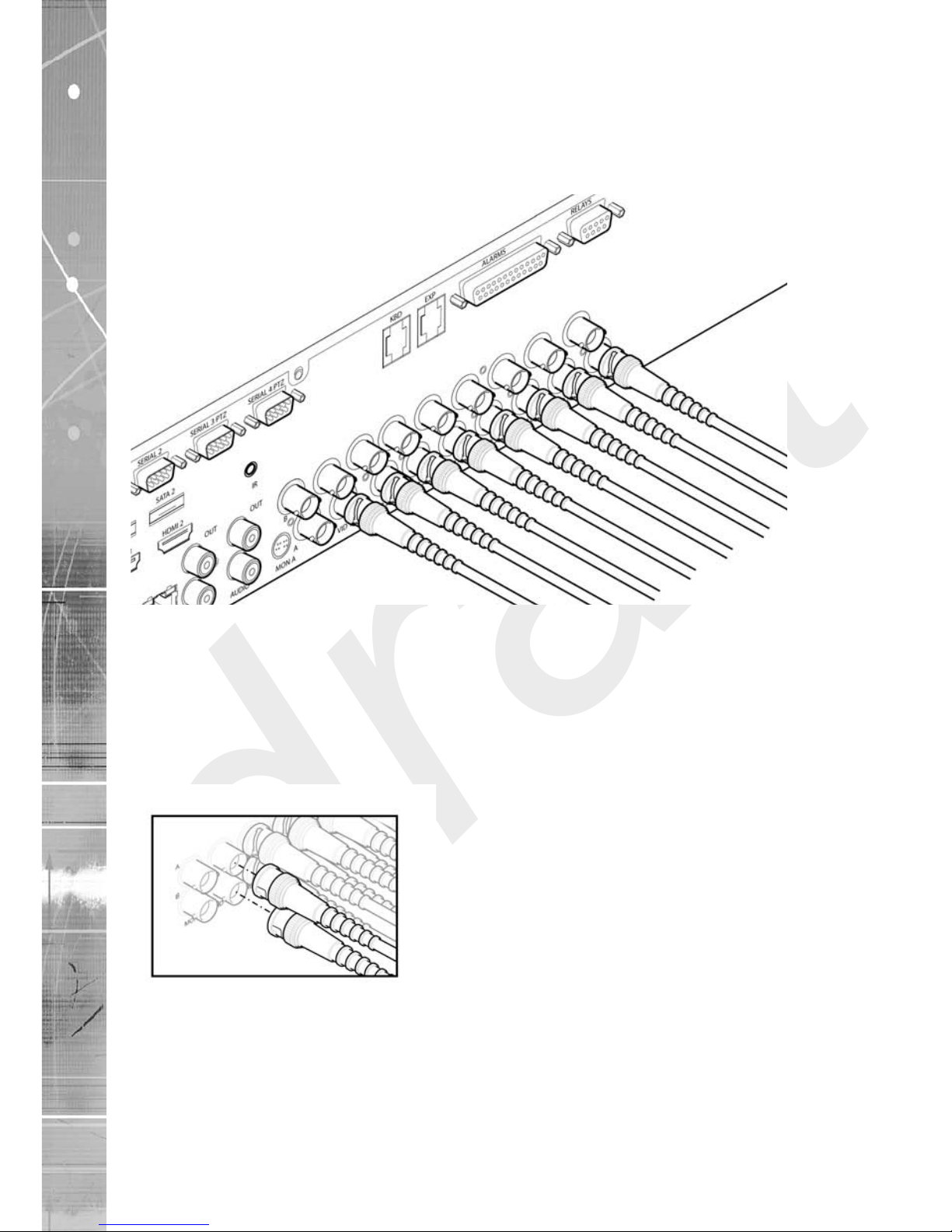
Step 1 Connecting Video
The DV-IP HD supports up to 8 connected Video Inputs via the 75Ω BNC connectors. Connect
cameras to the video inputs, starting from input 1.
8 and 16 channel variants have two rows of connectors providing video input and loop-through
support. It is possible to use either the top or bottom row of connectors; For consistency and quality
of installation, DM recommend one row is used for video inputs and the other for all required loop-
through connections onto other pieces of equipment e.g. monitors and matrices.
Note: Remember the last piece of equipment in line must be terminated.
Double termination (not removing termination from the unit) will result in the 1V peak to peak video
signal being crushed. This can reduce the colour rendition of the video source and may cause the
video signal not to be detected by the last piece of equipment i.e. the signal is no longer 1V peak-
to-peak.
5.12
draft
Dedicated Micros ©2008 13
DV-IP HD
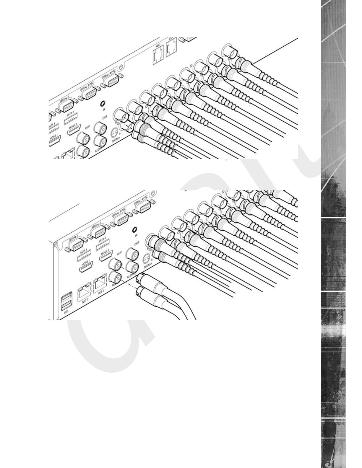
Step 2 Monitor
The DV-IP HD supports a main monitor via BNC ‘A’ and a spot monitor via BNC ‘B’.
Step 3 Connecting Audio
The DV-IP HD supports two channels of bi-directional audio, accessible through NetVu ObserVer.
Connect the audio equipment to the phono sockets AUDIO IN and AUDIO OUT. The audio channel
defaults to record camera 1.
The following modes of operation are supported:
• Challenge – intruders from a Remote Video Response Centre (RVRC)
• Listen – to local audio from a site at the RVRC
• Record - local audio from a site to accompany video
• Replay - all audio through a local Audio output (not supported when
Audio out is used as a challenge/PA source)
Note: The Audio output can be congured as a challenge output or as a replay output.

draft
Dedicated Micros ©2008
14
DV-IP HD
Step 4 Connecting to the Network
The DV-IP HD supports a 10/100Mbps auto-detecting network port. Use a CAT5 cable to connect
the unit to the network.
By default the unit is congured for DHCP (where the unit is automatically allocated an IP address
from the network DHCP server).
DNS (Dynamic Name Servers) is supported and therefore the unit can be assigned a name. This
removes the need for the unit to have a xed IP address and makes it easier for a remote user to
locate. Refer to the ‘Network’ menu section for further information regarding DNS.

draft
Dedicated Micros ©2008 15
DV-IP HD
3Step 5 Relays
The DV-IP HD supports up to ve 24V 200mA relays.
Relay Connector
Pin Connection
1 Relay 1 signal
2Relay 2 signal
3 Relay 3 signal
4Relay 4 signal
5 Relay 5 signal
9 Earth
Step 6 Alarms
The DV-IP HD supports 20 normally open/closed tamper proof alarm inputs, or one Global keyswitch
input with camera specic inputs congurable as entry/exit alarms. The alarms support tamper proof
detection using 1k in line and 5K end of line resistance. The DV-IP HD detects short circuit, open
circuit and contact closure. This functionality is part of the advanced alarms supported on NetVu
Connected products and includes features required for Central Monitoring. It is compatible with the
British Standard BS8418.
Relay Connector
Pin Alarm Input Connection
1 - 20 1-20
21-25 Earth Common

draft
Dedicated Micros ©2008
16
DV-IP HD
End Of Line Circuitry
The following describes the EOL tamper alarms circuitry needed when EOL has been congured.
There should be two resistive values within the tamper alarm circuitry. These must be located inside
the alarm device (furthest point from the unit).
The alarm state could be Normally Open or Normally Closed, however the tamper states are the
same for both settings.
Open, the resistive value is 6.8K ohms (1K + 5.6K).
Closed, the resistive value is 1K ohms, as the circuit does not see the 5.6K ohm resistor.
Open Circuit Tamper, the resistive value is innity as the circuit has been cut and therefore is ‘open’.
Short Circuit Tamper, the resistive value is 0 ohms.

draft
Dedicated Micros ©2008 17
DV-IP HD
Step 7 Connecting Serial Ports
Serial ports have two main uses:
1. Connecting twisted pair telemetry for PTZ cameras.
2. Providing text data recorded with the video e.g. Point of Sale.
Note: Telemetry cameras should be connected to Serial 3 and 4. Text data can be retrieved from
any serial port.
RS232
RS485
Step 8 Connecting a Keyboard
The DV-IP HD supports Dedicated Micro keyboards DM/KBC1 and DM/KBC2. Connect any of these
keyboards via the KBD connector situated on the rear of the unit.
Note: Refer to ‘Unit Operation’ for further guidance regarding supported keyboards.

draft
Dedicated Micros ©2008
18
DV-IP HD
Step 9 Connecting Telemetry Cameras
Simple Dome Connection
Pin connections for RS485 connection to a dome on serial port 3/4 are:
Dome Cable DV-IP HD Serial Connector
Yellow 1 TX+
Green 9 TX-
If the dome is being connected using an RS485 connection, the dome address should be set to
match the camera input number on the DV-IP HD i.e. if the dome is connected to video input 3,
the camera address should be ‘03’.
Dennard 2040 & 2060 Domes
A Dennard 2040/2060 Dome can be connected via either co-axial telemetry or RS485 twisted
pair.
If using co-axial telemetry the address switches should be set as:
Blue switch - F Yellow switch - D
DM Oracle Domes
A DM Oracle dome can be connected via either co-axial telemetry or RS485 twisted pair. Oracle
Domes are congured using the specic pages available in the unit software, refer to ‘Oracle
Dome Conguration’ for more information.
The DM Oracle Dome has three address switches, refer to the Oracle Dome documentation for
more information on hardware confguration.
UTC
Red - 1
Blue - N/R
Yellow - N/R
Serial
Red - 2
Blue - Camera Number
Yellow - Camera Number

draft
Dedicated Micros ©2008 19
DV-IP HD
Step 10 Connecting Power
The DV-IP HD has an internal power supply unit. Connect the mains lead to the unit and then to
the wall socket, or to a fused spur connection. Check local regulations before installation. Some
countries require an Alarm/Security device be connected to a fused spur and not a wall outlet
socket.RF
Advanced Installation
Connecting Storage devices
Images are recorded to the internal hard disk for instant playback and searching by the operator.
The capacity of the internal disk effects the amount of images and time period that can be recorded.
The internal hard disk is a temporary storage device as images are overwritten after a set period.
If images need to be held for a longer time period, external storage is required. The SATA ports on
the rear of the unit are used to connect to external storage devices. The unit can support multiple
external hard disks. To maintain an effective SATA link, the length of all cabling from the unit to the
connected device should not exceed two metres.
The unit’s operating system will continue to utilise the internal hard disks if the external hard drive
encounters a problem.
Dedicated Micros Managed Storage Expansion units
A DM Managed Storage Expansion unit is connected via the SATA port. A Managed Storage unit
provides high capacity, environmentally managed storage in a single box. Disk temperature is
maintained at a constant level and the disk management system ensures only disks in operation are
spun. Both of these features help extend drive life.
For further information regarding the DM Managed Storage Expansion unit, please contact
Dedicated Micros technical support team.

draft
Dedicated Micros ©2008
20
DV-IP HD
Conguring the Unit
The unit can be congured either on the local monitor or over the network using a PC with Internet
Explorer or a similar browser. Both interfaces are the same.
Accessing the menus on a local monitor
1. The Conguration pages can be displayed on the local monitor by pressing the MENU
button on the IR Remote Control.
Note: If the IR Remote Control does not open the menu, press the DVR button to make sure it is
in DVR mode, then press the MENU button again.
Accessing the menus on a PC web browser
Locating the Unit IP address
The IP address of the unit is required to access the web pages. It can be identied from the local
menu pages; using the local monitor, press the MENU button on the IR Remote Control and
navigate to the System menu to nd the DHCP assigned IP address.
If DNS (Domain Name Server) is not to be used, it is important to set a xed IP address so that the
same URL can be entered to contact the unit every time.
If a permanent IP address is not assigned to the unit, it will attempt to contact the DHCP server
every time it starts up. If for any reason, a DHCP server cannot allocate an IP address to the unit, a
default IP address will be used. It is recommended that DNS be used as assigning a name will make
it easier for a remote user to locate the unit. DNS data can be congured via the Network menu.
6.11
Accessing the Conguration Web Pages
The unit can be congured using the on-board web pages. To access these:
1. Launch Internet Explorer (or other web browser package).
2. Type the URL for the unit (IP address or domain and unit name).
3. The System Settings menu page will be displayed.
Table of contents
Other Dedicated Micros Recording Equipment manuals

Dedicated Micros
Dedicated Micros SD Advanced Operating instructions

Dedicated Micros
Dedicated Micros PICKAPOINT User manual

Dedicated Micros
Dedicated Micros DV-IP Express Instruction Manual
Dedicated Micros
Dedicated Micros Digital Sprite Lite User manual

Dedicated Micros
Dedicated Micros SD Range Operating instructions

Dedicated Micros
Dedicated Micros PICKAPOINT User manual


