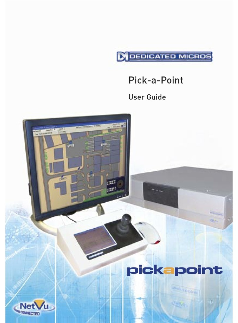
Dedicated Micros PICKAPOINT User manual

1
Pick-a-Point
Installation Guide
To be retained
by installer

2
Table of Contents
Software Version 85
Overview ..........................................................................3
Basic Configuration ..........................................................4
Preparation .......................................................................8
Hardware Installation .......................................................9
Configuration ..................................................................10

3
Overview
Pick-a-Point is a dedicated IP keyboard solution
with joystick control that is designed to replicate the
traditional analogue matrix, offering digital reliability
and retrieval speed. Integration with existing analogue
systems is seamless, giving the station control over all
servers, domes, DVR’s and cameras.
The Pick-a-Point system interfaces with the video
servers, telling the server where to display camera
feeds on a monitor wall.
It can operate as an additional control point on an
existing Pick-a-Point system, or work standalone
to provide composite viewing and control of any
Dedicated Micros NetVu Connected Server, DVR or IP
Camera.
The system can quickly and easily be configured
to communicate with servers and cameras over an
existing network.
Using the graphical user interface, it is possible to provide a very effective method of accessing different sites
and cameras quickly and efficiently.
The whole system is very easy to install and can be up and running within an hour. The step by step instructions
set out in this manual will enable the installer to provide a full and effective interface with a customers existing
system, or set up a new monitoring station.
This manual does contain some restricted information and should not be left with the end user. Access to
certain configuration menus detailed in this manual should only be available to installation engineers. It is
recommended that, for security and maintenance of an efficient system, access codes which are listed within
this manual, are not given to end users.
More information is available from the Dedicated Micros Web site.
Go to
www.dedicatedmicros.co.uk

4
Basic Configuration
Connections at the rear of the unit
COM2 MIC LINE IN LINE OUT
HEAD
PHONES
SVGA
NET
KBD
USB USB
COM1
COM A COM B COM C COM D COM E COM F COM G COM H
Interface
SVGA SVGA Monitor Connection
KBD PS2 qwerty Keyboard - can be removed after configuration
Mouse Microsoft Wheel Mouse Optical 1.1A USB and PS/2 Compatible
Network and Communications
NET 10/100 / 10BASE-T / 100BASE-TX / 1000BASE-TX Network Port
USB 4 x USB 2.0 Ports
Mic 3.5mm jack socket for Microphone
Line In 3.5mm jack socket for Line In
Line Out 3.5mm jack socket for Line Out
Headphones 3.5mm jack socket for headphones
Data
COM Ports
COM1 & COM2 RS-232
COM A Pick-a-Point keyboard socket
COM B Serial Alarms connection
COM C - COM H Spare RS-232/RS-422 Ports
LED’s
Power LED adjacent to COM H Socket
Options
CD Writer Freecom Classic DVD+/-RW Double Layer USB 2.0
Touch Screen 3M Capacative

5
Sample Installation Diagram
COM2 MIC LINE IN LINE OUT
HEAD
PHONES
SVGA
NET
KBD
USB USB
COM1
COM A COM B COM C COM D COM E COM F COM G COM H
USB CD Writer
PC Monitor
Power
Supply
Power
Supply
PS2 Keyboard - only
required for commissioning
MousePick-a-Point
Keyboard
DVR
Network switch
Monitor Wall
Pick-a-Point
12345678
9 10 11 12 13 14 15 16
12345678
9 10 11 12 13 14 15 16
EVENT
GOTO
COPY MODE MENU
LIVE PLAY SPOT RECORD
Design of the manual
The manual has two parts:
1. Installation
–Giving details of how to install the unit and connect external devices.
2. Setup
–Giving details of the configuration menus of the unit.

6
Important Safeguards
Read Instructions
All the safety and operating instructions should be read before the unit is operated.
Power Sources
This unit should be operated only from the type of power source indicated on the manu-
facturer’s label.
Servicing
Do not attempt to service this unit yourself as opening or removing covers may expose
you to dangerous voltage or other hazards.
Refer all servicing to qualified service personnel.
Ventilation
Ensure unit is properly ventilated to protect from overheating.
All the safety and operating instructions should be read before the unit is operated.
To prevent fire or shock hazard, do not expose this equipment to rain or moisture. The lightning flash with
arrowhead symbol within an equilateral triangle is intended to alert the user of this equipment that there are
dangerous voltages within the enclosure which may be of sufficient magnitude to constitute a risk of electric
shock.
WARNING
This is a class A product. In a domestic environment this product may cause radio interference in which case
the user may be required to take adequate measures.
Regulatory Notes and FCC and DOC Information
(USA and Canadian Models Only)
Warning: This equipment has been tested and found to comply with the limits for a Class A digital device,
pursuant to part 15 of the FCC rules. These limits are designed to provide reasonable protection against
harmful interference when the equipment is operated in a commercial environment. This equipment generates,
uses, and can radiate radio frequency energy and, if not installed and used in accordance with the instruction
manual, may cause harmful interference to radio communications. Operation of this equipment in a residential
area is likely to cause harmful interference in which case the user will be required to correct the interference at
their own expense.
If necessary, the user should consult the dealer or an experienced radio/television technician for corrective
action. The user may find the following booklet prepared by the Federal Communications Commission helpful:
“How to Identify and Resolve Radio-TV Interference Problems”.
This booklet is available from the US Government Printing Office, Washington, DC20402, Stock No. 004-000-
00345-4.

7
This reminder is provided to call the CCTV system installer’s attention to Art. 820-40 of the NEC that provides
guidelines for proper grounding and, in particular, specifies that the cable ground shall be connected to the
grounding system of the building, as close to the point of cable entry as practical.
CE Mark
If this product is marked with the CE symbol it indicates compliance with all applicable directives.
Directive 89/336/EEC.
A ‘Declaration of Conformity’ is held at Dedicated Micros Ltd.,
11 Oak Street, Swinton, Manchester M27 4FL.
Choosing a location for installation
The Pick-a-Point workstation is designed to be desk or rack mounted. The following precautions must be taken
during installation:
• Openings in the unit’s case are provided for ventilation. To prevent overheating, these openings should
not be blocked or covered.
• Ensure there is a 1” (2.54 cm) gap on either side of the unit.
• When stacking units, ensure there is at least a ½” (1.3 cm) gap between each unit.
• Ensure the unit is not located in an area where it is likely to be subjected to mechanical shocks.
• The unit should be located in an area with low humidity and a minimum of dust. Avoid places like damp
basements or dusty hallways.
• If the unit is to be installed in a closed assembly, the maximum operating temperature must not exceed
82°F (28°C).
• Ensure there is reliable earthing of the mains outlet when fitted to supply connections, other than direct
connections, to the branch circuit.
• Any branch circuit supplying the unit must be rated 15Amps.
• It is recommended that an uninteruptable power source be connected to the unit in case of power failure,
to ensure continuous operation of the unit.

8
Preparation
Before beginning commissioning, it is recommended that all the maps for all the sites to be monitored by the
Pick-a-Point system be created ready for installation.
Pick-a-Point uses a graphical interface to help the operator navigate quickly around the sites being monitored.
Well planned and laid out maps will help in this task.
Best Practice
Each site should have an overview map showing all the sub sites that can be accessed via the station. Once
the system has been configured, the operator will click on a ‘hotspot’ on the main map to open a sub-map,
showing all the available cameras within that area. All maps should be created before commissioning begins.
Map spec
• All maps should be created in JPEG format.
• 1024 x 702 pixels
Note: There are many different options when saving JPEG format. Some of these may not display
satisfactorily. This can be prevented by opening the finished correctly sized JPEG using the Microsoft
Paint program available on most PC’s and then re-saving.
The finished maps can then be saved onto a USB memory stick (or CD if there will be a USB CD drive
available) so they can be used in the commissioning process.
Installing the unit
Before you start
Packing List
Ensure you have the complete contents of both boxes before beginning commissioning.
Box 1 Box 2
Pick-a Point unit Pick-a-Point Keyboard
Power supply for Pick-a-Point unit Plug top power supply for Pick-a-Point keyboard (UK/US/Europe)
Mains lead for UK/USA/Europe RS-485 keyboard cable (2m) RJ45 - RJ45
PS2 querty keyboard Breakout box - to increase keyboard range
Optical USB mouse Manual for Pick-a-Point keyboard
Rack mounting ears for Pick-a-Point unit
Other Information required
• Static IP address for the Pick-a-Point
• Clients preferred naming convention for cameras/servers
• List of camera locations
• Clients preferred numbering convention for cameras
• List of Server IP addresses
• Camera inputs into each server
• List of Users and levels of access required

9
Hardware Installation
The workstation can be kept remote to the Pick-a-Point keyboard.
The Pick-a-Point workstation will require;
• 3 power outlets
• RJ45 connection to Cat5 network
To install the hardware;
1) Connect the qwerty keyboard
2) Connect the Pick-a-Point keyboard
3) Connect the monitor
4) Connect the USB mouse. Do not connect any other USB devices.
5) Finally, connect the power
Note: Do not plug in the network at this time. Initial installation and configuration will be quicker offline. The
network can be installed once the basic setup is complete.

10
Configuration
The workstation will boot and automatically launch the Pick-a-Point program in User mode. To gain access to all
the menus required for full configuration, the unit must be in Engineer mode.
To begin configuration;
To log off;
1) Touch or click on the ‘Log Off’ button on the menu bar. The Log Off window will appear.
2) Enter the four digit pin code (9999).
3) The ‘Logged Off’ window will be displayed.
To log on;
1) Touch or click on the red area and the ‘Log On’ button on the menu bar.
2) Enter the appropriate four digit PIN code.
3) Log back on using the Engineers login code. This is a four digit code calculated using the current date,
multiplied by six, and then made up to four digits by using zero’s at the beginning of the number.
Therefore, the login for the first day of the month would be;
First of month 01
x 6 = 6
plus zeros to make up 4 digits = 0006
Login for the 24th of the month would be;
Date of month 24
x 6 = 144
plus zeros to make up 4 digits = 0144
Note: This password gives access to the higher configuration levels of the workstation. It should not be
disclosed to unauthorised personnel. Disclosure could lead to systems being altered and the efficiency
being adversely effected.

11
The workstation screen is divided into two sections pictured below.
The menu bar is displayed across the top of the screen, with the map window below.
Menu Bar
The menu bar at the top of the screen allows access to the available menus. These will change according to the
log in used. The menu bar, shown below, is what an Engineer will have available. A description of each button
function is listed below.
1 2 3 4 5 6 7 8 9 10
11 12 13 14 15

12
User Button Functions
1 Displays the key number selection from the keypad.
2 Displays the currently selected system camera number.
3 Opens the ‘Log Off’ system window (see Logging On and Off).
4 Allows access to most of the main Engineer functions and menus
5 If an MPEG-4 or MJPEG video source has been selected, there will be an
option to dynamically switch the view between JPEG and MPEG modes.
The button will display the alternative option. The current feed will be
shown on the monitor.
6 Opens the ‘Multi Screen’ window (see Multi-Screens).
7 Allows the operator to set the workstation time and date (see Setting The
Time And Date).
8 Logs / recalls a time, date and camera number when a suspicious event
occurred (see Observed Events).
9 Opens the Options Menus (See below)
10 Displays program version information.
11 Returns the display to the top level map.
12 Starts or stops a sequence on the currently selected monitor (see
Sequences).
13 Opens the DVR search and playback window (see DVR Search /
Playback).
14 Displays a list of sites / map levels (see Site list).
15 Allows the monitor selection to be changed (see Changing monitors).

13
Options Menu
The Options Menu is accessed by clicking on the Exit button on the menu bar.
This menu allows access to some of the functions that can be used for system maintenance.
System Displays information about the Hardware within the workstation case
Explorer Allows navigation of the workstation hard drive
Display Allows alterations to be made to the workstation monitor settings
Task Manager Shows all the software tasks running on the workstation
Restart CPU Enables a reboot
Shut Down Shuts down the workstation
End Program Closes the Pick-a-Point software
Close Options Menu Closes this menu
Note: In the unlikely event that the workstation locks up , there is the facility to open an Explorer window, to
allow access to the hard drive. Using the qwerty keyboard, type “x” plus the engineering log in.

14
Step One - Adding Maps
The maps form the backbone of the graphical user interface for the Pick-a-Point system. These should have
been created beforehand in line with the specification mentioned earlier in this manual.
To install the maps;
1) Connect the USB media (memory stick or CD drive) into one of the available USB sockets at the back of
the Workstation.
2) Click ‘File -> Edit Map List’ to open the map dialog box.
This screen will allow maps to be uploaded or deleted.
3) Click ‘Add map’. This will create a new entry in the Map list. Change the automatically generated entry
(“NewSite-00:00-XX/XX/XXXX) in the ‘Map Name box’ to an appropriate title.
Note: Maps are listed alphanumerically. Try to install maps in a logical order to make navigation and linking
easier later.
One suitable method is to number each site in hundreds, with the main site map named
“100 - Main Site 1”, “200 - Main Site 2”, etc, with sub sites being numbered sequentially
(“110 - Building 1 - Site 1”,”120 - Building 2 - Site 1” ; “210 - Building 1 - Site 2”,
”220 - Building 2 - Site 2”). Taking care over the naming structure will make subsequent stages easier.
4) Click on the button next to the “Map Path’ dialog box and navigate to the USB media containing the
prepared maps. Select the correct map and click ‘OK’.
5) Click on ‘Save Map Details’. The map will be copied from the USB media into the correct location within
the Workstation. A sample of the map will be displayed on the Main Screen.
6) Sites can be categorised as either local or remote. Local sites are linked via hotspots and the cameras
are navigable by the touchscreen keyboard. Typical scenario would involve a town centre being stored
as a Local site, with interlinked maps, with schools being brought in as Remote sites overnight.
7) Click ‘Site Active’ once the map is ready to be used and click on ‘Save Map Details’.
Note: Maps can be prepared and installed prior to cameras and alarms being commissioned on site and left
inactive on the workstation.

15
Adding Servers
Ensure you have a list of clients IP addresses and have decided on a naming convention for each of the sites to
be monitored.
To add a Server or Decoder;
1) Click on ‘File -> System Setup’ on the main menu bar.
2) Select the ‘Server List’ tab
3) Add the information in the panel to the right hand side of the Server List. This should comprise of;
• Server IP address
• Server name
Note: Use an appropriate name to help identification.
• Username (if required to access the server)
• Password (if required to access the server)
Note: Ensure the username and password give an appropriate level of access to the user.
• Type of server
Note: Use “New DS2” for NetVu connected units, use “DS2/BX2/D4” for CGI models.
4) Click “Update” to add the server to the list.

16
Adding Monitors
This section will configure the monitors under workstation control. The workstation instructs the decoders and
servers with where each camera is to be displayed on the monitors. The system supports up to 200 monitors.
To add a Monitor;
1) Click on ‘File -> System Setup’ on the main menu bar.
2) Click on the ‘Monitor Setup’ tab.
3) Use the drop down menu to select the number of Monitors that this Pick-a-Point station will control.
It is now necessary to configure each monitor.
4) Use the drop down menu to select which monitor is being configured.
5) Select the Monitor Type from the drop down list.
Digital Matrix This option supports a DM decoder output for the selected monitor.
BBV Matrix This option supports a BBV TX1500 or FBM analogue matrix monitor output.
BBV Matrix + Remote This option supports a BBV TX1500 or FBM analogue matrix monitor output
Monitor Switching to display the output from a remote DM decoder, and is used for seamless
integration of digital and analogue matrices.
6) The Monitors are displayed in numeric order on screen. It is possible to change the monitor number
and thereby change its position on screen. This additional flexibility is to enable consistency on the
video wall (for instance, if cameras are feeding from different servers). This does not have any effect on
Multiscreens.
7) Type the IP address of the decoder that will provide the video source for this monitor.
8) Select the decoder output that will provide the video signal for this monitor.

17
9) If a BBV analogue matrix was selected in the Monitor type, this drop down box to select ‘Analogue
Matrix Monitor Number’ will be usable. Select which monitor output will be used on the BBV analogue
matrix.
10) Use ‘Local Analogue Matrix Input’ to specify the BBV matrix input that will be used to view a remote DM
decoder monitor output.
11) Tick the ‘Monitor Visible’ box if the monitor is to be displayed on the video wall. If the monitor is not
visible, it will still be available to display Alarms and from the multiscreen window.
12) Click on “Save Monitor Details” to update the list.

18
Adding External Devices
Use the drop down menu to select which external device will be configured, then assign a drive letter.
To add an External Device;
1) Click on ‘File -> System Setup’ on the main menu bar.
2) Select the ‘External Devices’ tab.
3) Use the drop down menu to selec which device will be configured.
4) Assign a drive letter using the drop down menu.
5) Click ‘Save’ to assign the chosen drive letter to the chosen drive.
This menu is available via the Supervisor login and can be configured or edited at a later date if required.

19
Configuring the Observed Events Menu
There are four definitions that can be assigned to every Observed Event, along with a unique User Defined
option. These definitions will appear in the drop down list above the user defined option. These should be
configured as general descriptions of possible events e.g. Suspicious Vehicle, Unidentified Person etc.To
configure the Observed Events;
1) Click on ‘File -> System Setup’ on the main menu bar.
2) Select the ‘Observed Events’ tab.
3) Enter a different reason into each box. This menu is also available to the Supervisor login and can be
edited at a later date if required.

20
Setting up Permitted Users
Part of the initial system configuration should include setting up at least one Supervisor login. This will give an
appointed member of staff the permissions necessary to administer some of the features of this system, and
enable the creation and deletion of lower access user accounts.
To set up a new user;
1) Click on ‘File -> System Setup’ on the main menu bar.
2) Select the ‘Pass Numbers’ tab.
3) Enter the User Name in the text box.
4) Enter a suitable unique number for that user.
5) Set the User Level. An Engineer login can create either User or Supervisor level logins, whereas a
Supervisor can only create Users.
6) Click Update to add this user to the roster.Note: It is recommened that the installer create at least one
Supervisor and one User level login for each installation.
To delete a user;
1) Click on ‘File -> System Setup’ on the main menu bar.
2) Select the ‘Pass Numbers’ tab.
3) Select the User in the table of users.
4) Click on ‘Delete Selected User’ in the right hand panel. The User will be removed from the list and the
login deleted.
Other manuals for PICKAPOINT
2
Table of contents
Other Dedicated Micros Recording Equipment manuals

Dedicated Micros
Dedicated Micros PICKAPOINT User manual

Dedicated Micros
Dedicated Micros SD Range Operating instructions

Dedicated Micros
Dedicated Micros DV-IP HD Operating instructions

Dedicated Micros
Dedicated Micros DV-IP Express Instruction Manual

Dedicated Micros
Dedicated Micros SD Advanced Operating instructions
Dedicated Micros
Dedicated Micros Digital Sprite Lite User manual