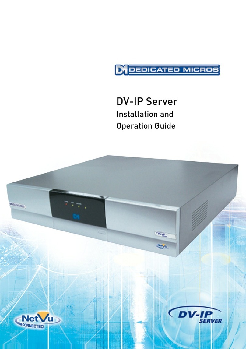
Dedicated Micros DV-IP User manual


Dedicated Micros Ltd Page i
Contents
Introduction to Networks ............................................................................................................................. 1
What is a Network? ................................................................................................................................. 2
Equipment and Protocols .................................................................................................................... 3
Introduction ............................................................................................................................................... 12
How this Manual has been Constructed ............................................................................................... 13
Features of the DV-IP Server................................................................................................................ 14
Installing the DV-IP Server ....................................................................................................................... 17
DV-IP Server Connections and LEDs ................................................................................................... 17
Rear Panel Connection ..................................................................................................................... 17
Front Panel LEDs .............................................................................................................................. 19
Unpacking the DV-IP Server ................................................................................................................. 20
Safety Notes.......................................................................................................................................... 20
Location ............................................................................................................................................. 20
Electrical Connections ....................................................................................................................... 21
Power Sources .................................................................................................................................. 21
Servicing ............................................................................................................................................ 21
Ventilation .......................................................................................................................................... 21
Lightning Strike.................................................................................................................................. 21
Regulatory Notes FCC and DOC Information....................................................................................... 22
CE Mark............................................................................................................................................. 22
Simple Installation ................................................................................................................................. 23
Tools Required .................................................................................................................................. 23
Recommended PC Specification....................................................................................................... 24
Step 1 Connecting the Rack Mounting Brackets............................................................................... 25
Step 2 Connecting Video Sources..................................................................................................... 26
Step 3 Connecting to the Network..................................................................................................... 26

Page ii Dedicated Micros Ltd
Step 4 Connecting serial devices ...................................................................................................... 27
Step 5 Termination Dip Switches ...................................................................................................... 28
Step 6 Connecting Power.................................................................................................................. 29
Step 6a Allocating an IP Address ...................................................................................................... 29
Step 7 Locating the DHCP Allocated IP Address.............................................................................. 33
Advanced Installation ............................................................................................................................ 34
Tools Required .................................................................................................................................. 34
Step 8 Looping Cameras................................................................................................................... 35
Step 9 Connecting Alarm Inputs........................................................................................................ 35
Step 10 Connecting Relays ............................................................................................................... 38
Step 11 Connecting 485 Bus Devices ............................................................................................... 39
Step 12 Connecting Audio Equipment............................................................................................... 39
Step 13 Connecting External Storage (JBOD / RAID) ...................................................................... 40
Step 14 Setting and Enabling Passwords .........................................................................................45
Configuring the DV-IP Server ................................................................................................................... 49
Web Page Icons .................................................................................................................................... 49
Accessing the Configuration Web Pages.............................................................................................. 50
Simple Configuration................................................................................................................................. 51
How to Configure Global Parameters ................................................................................................... 51
How to Enable System Features........................................................................................................... 53
BS8418 Functionality......................................................................................................................... 55
How to Configure Video Inputs and Standard Record Settings............................................................ 56
Configuring the Network Settings of the DV-IP Server ......................................................................... 61
How to Select and Enable Coaxial Telemetry....................................................................................... 64
Telemetry Setup Page....................................................................................................................... 65
How to Enable Serial Telemetry............................................................................................................ 66
Telemetry Setup Page....................................................................................................................... 68
Supported Modems/TA’s ................................................................................................................... 69
How to Configure Matrix Control ........................................................................................................... 70

Dedicated Micros Ltd Page iii
Advanced Configuration ........................................................................................................................... 73
How to Configure Variable Recording................................................................................................... 73
RAM Disk........................................................................................................................................... 75
How to Enable Audio Recording ........................................................................................................... 76
How to Configure the Video Inputs for VMD ......................................................................................... 78
Walk Test........................................................................................................................................... 86
How to Enable and Configure Alarms................................................................................................... 86
How to Configure the Relay Connections ............................................................................................. 94
How to Configure Connect/ Dial, FTP, SMS and Email on Alarm ........................................................ 96
How to Configure Connect/Dial on Alarm..........................................................................................96
How to Configure FTP Settings for Archiving Images..................................................................... 102
How to Configure SMS Text messaging ......................................................................................... 105
How to Configure Email Settings..................................................................................................... 110
How to Protect or Un-protect Images.................................................................................................. 112
How to Configure the Alarm Database ............................................................................................... 114
How to Configure an Alarm Schedule................................................................................................. 115
How to Configure Holiday Profiles................................................................................................... 117
How to Configure Text in Image Functionality .................................................................................... 119
How to Enable and Configure the Onboard Firewall........................................................................... 122
IP Address Range and Subnet........................................................................................................ 125
How to Enable System Logs ............................................................................................................... 126
How to Enable and Configure Watermarking...................................................................................... 127
How to Enable and Configure the Webcamera functionality .............................................................. 129
DV-IP Server Tools................................................................................................................................. 134
Video Scope ........................................................................................................................................ 134
Audio Trace ......................................................................................................................................... 136
Relay Test Page.................................................................................................................................. 136
Watermarking ...................................................................................................................................... 138
System Variable .................................................................................................................................. 138

Page iv Dedicated Micros Ltd
Reset ................................................................................................................................................... 138
Reviewing the DV-IP Server Logs .......................................................................................................... 139
Connection Log ................................................................................................................................... 139
Anonymous FTP Log........................................................................................................................... 140
Security Log ........................................................................................................................................ 140
E-mail Log ........................................................................................................................................... 141
Sent Message Log .............................................................................................................................. 142
FTP Download Log.............................................................................................................................. 142
Logfile.................................................................................................................................................. 142
Logfile Backup..................................................................................................................................... 143
Appendix A - Resetting the DV-IP Server............................................................................................... 145
Reset using the Web Interface............................................................................................................ 145
Reset using Telnet .............................................................................................................................. 146
Appendix B – DV-IP Server .ini Files ...................................................................................................... 147
Editing the ini Files using FTP Client Application................................................................................ 147
Structure of the Files ........................................................................................................................... 150
hosts ................................................................................................................................................ 150
modems.ini .......................................................................................................................................... 151
paths.ini ........................................................................................................................................... 152
USER.ini .......................................................................................................................................... 154
vidcfg.ini........................................................................................................................................... 154
WEBUSER.ini .................................................................................................................................. 156
Editing .ini Files using DV-IP Backup Utility ........................................................................................ 157
Appendix C – Port Assignment on the DV-IP Server ............................................................................. 162
Port Allocation ..................................................................................................................................... 162
Appendix D – DV-IP Server Serial and Network Cables ........................................................................ 164
DM RS232 Debug Cable (supplied).................................................................................................... 164
Straight-through Network Cable.......................................................................................................... 165
DM 485 Bus Cable (supplied) ............................................................................................................. 166

Dedicated Micros Ltd Page v
Cross Over Network Cable ................................................................................................................. 167
DM RS232 Null Modem Cable ............................................................................................................ 168
Nokia 30 Cable.................................................................................................................................... 169
Appendix E – IP Address Range and Subnets....................................................................................... 170
IP address and Subnet Masks ............................................................................................................ 170
Classes of Networks ........................................................................................................................... 171
Class A ............................................................................................................................................ 171
Class B ............................................................................................................................................ 172
Class C ............................................................................................................................................ 173
Calculating IP Address Range ............................................................................................................ 173
Class A table.................................................................................................................................... 174
Class B table.................................................................................................................................... 175
Class C table ................................................................................................................................... 176
Appendix F – SMS Message Format...................................................................................................... 177
Command Format ............................................................................................................................... 177
SMS Commands ................................................................................................................................. 177
Callback ........................................................................................................................................... 177
SMS Reports....................................................................................................................................... 178
Startup ............................................................................................................................................. 178
Alarm ............................................................................................................................................... 179
VMD................................................................................................................................................. 180
Camfail............................................................................................................................................. 181
Additional Information ............................................................................................................................. 182
Command Reference List ................................................................................................................... 182

Page vi Dedicated Micros Ltd

Dedicated Micros Ltd Page 1
Introduction to Networks
The following will give you an entry level introduction to protocols used with Ethernet networks,
equipment that makes up the network and how these work together.
It should help you when installing the DV-IP Server within a Local Area Network (LAN), or Wide Area
Network (WAN). First we will identify some of the terminology we will use in this section;
Server – This is used in many ways in networking, a central server where we retrieve and save all our
documents, an e-mail server that receives all e-mails and then forwards them to the relevant recipient, or
a video server that serves video (live and playback) onto a network so a single or multiple users can
access it.
Host – Host are any device that is connected to a network via a Network Interface Card; e.g. printers,
PC’s, web cameras.
Client Application – This is the application that is used to receive and translate the information from the
server, Microsoft Word, Internet Explorer, Dedicated Micros DV-IP Viewer software.
Ethernet – Ethernet is a network that allows multiple applications to share the same ‘piece of string’.
Ethernet is the largest installed network technology in the world.
NIC – Network Interface Card. This is the interface that enables a device to connect to the network.
These are available for any network; Asynchronous Transfer Mode, token ring, Ethernet and can range
in sophistication and speed (more capability more cost). The DV-IP Server has a 10/100Mbps auto-
detecting NIC.
LAN – Local Area Network. A LAN has specific characteristics; there is a geographical limitation that
means more often than not a LAN is within the same building, it is usually owned and managed by the
Company and more commonly the speed (how quickly information is transmitted from one place to
another) is 100Mbps +.
WAN – Wide Area Network. A WAN is a network that links two LAN’s together. There are numerous
WAN links available (ISDN, DSL) and are usually supplied by telecommunication providers. It is
important to remember that the speeds of WAN links are usually much slower than the LAN, this can
result in the video stream slowing down, and however the video quality will remain the same.
VPN – Virtual Private Network. A VPN is an alternative to transmitting information over a distance. These
can be provided by Internet Service Providers and it acts as a tunnel through their network infrastructure
to transport your data from one location to another. The link is private and secure and gives a seamless
link, i.e. a virtual network that is part of your own network.

Page 2 Dedicated Micros Ltd
What is a Network?
A network is a communication path allowing two or more devices to share/transmit data; e.g. telephone
to telephone exchange, camera to matrix, server to host.
If we look at this in terms of the DV-IP System solution the devices are the DV-IP Server and the Client
Applications, the communication path is the Ethernet network (LAN or WAN).
Today’s networks have the capability to support multiple applications running across the same hardware
and cabling infrastructure; IP telephony, Door Access, CCTV.
This is bringing the ability to have a single network for whole of the Building Management requirements;
IT, Security, lighting and telephone systems, offering us a converged solution.
The DV-IP Server sits on an Ethernet network and allows video (Live and Recorded) to be transmitted
across the network (LAN or WAN) for a single or multiple user to access. Therefore the rest of this
section will detail the equipment and protocols within an Ethernet network.

Dedicated Micros Ltd Page 3
Equipment and Protocols
A network consists of hardware, cabling and protocols, the following describes the most common
devices and protocols that you will be introduced to when installing a DV-IP Solution.
A network infrastructure generally consists of a high speed ‘bus’ backbone that connects to hardware to
introduce a ‘star’ topology at the edge of the network.
A bus network has the advantage of speed, i.e. no hardware to slow down the data being transmitted,
but the disadvantage is the whole network is a point of failure. If a cable is cut the whole network will no
longer function, and it is also very difficult to find the area on the cable that has the problem.
A star network introduces hardware, therefore reducing the point of failure to a single device. Identifying
this failure is extremely easy and quick as there are software applications that run on these devices
allowing for feedback on packet loss, usage (capacity), failure, etc. The disadvantage is the introduction
of hardware adds time to the transmission of the information; however the advantages are far more
significant.
A combination (described above) of bus and star gives speed at the centre of the network where it is
required (route of most of the network data) while adding security and single points of failure with the
introduction of hardware.

Page 4 Dedicated Micros Ltd
Hub
A hub is an unintelligent device and in simple terms acts as an electrical repeater, i.e. what comes in is
re-amplified and transmitted onwards out of every port on the hub. The disadvantage of this is data is
distributed to every host on the network even if they have not requested the data. This can have an
affect on the efficiency of a network especially when transmitting large files such as video. Not
recommended in real time (voice, video) application.

Dedicated Micros Ltd Page 5
Switch
There are many Ethernet switches available this section will not highlight any specific switches but
explain how they work within a network.
A switch enables a star topology for a network. A switch is an intelligent device and uses information
(that is found in the Header of the data being transmitted) to identify where the transmit host and the
destination host is located on the network. From this information the switch will begin to build up
information on its network.
There are different types of Ethernet switches available and depending on the protocols you are using
will depend which switch would be more appropriate.
Protocols such as UDP multicast would require a more sophisticated switch (Layer 3 Switch) that has
the ability to analyse, in more detail, the information held in the packet Header and identify the IP
address as well as the hardware address of the transmit host and destination host.

Page 6 Dedicated Micros Ltd
Router
A Router or more commonly known as a ‘Gateway’ is the device that acts as a filter for transmission of
information from one network to another.
The router looks at the data and identifies if it is for a host on the LAN or if it is to be transmitted across
the WAN, what is the priority of the information (optimum path = high priority), is it time critical and what
speed is it being transmitted.
ISDN
DSL
ATM
A router also has the capabilities of converting one medium to another, e.g. Ethernet to ISDN and
buffers the data to slow high speed information transfer is successful over slower speed links, 10Mbpt to
128kbps.
A simple router can have a single LAN and WAN connection, where more sophisticated routers have a
LAN and multiple WAN connections (ISDN as a back up route, DSL, E1 as the main transmission paths)
and will identify the optimum route for the data to be transmitted.
IP Internet Protocol
The World Wide Web protocol, IP sits on top of the network hardware (described above) and is
responsible for transmission of Ethernet (or other networks such as Token Ring) packets to be sent from
host to host across the LANs, WANs and the WWW.
Any device connected to a network must have a unique address to identify who and where it is, this
address is an IP address, see below for more information on IP Addresses.

Dedicated Micros Ltd Page 7
Digital Data
Letter
IP Datagram
Envelope
Network
Postal Sytsem
IP Header
Mr Smith
112 Long Drive
California
CA13302
USA
Mr Smith
----------------------------------- -------
----------------------------------- ---------
-------------------------------
----------------------------------- --
-----------------------
--------------------------
--------
-------
The hardware in a network (switches and routers) use the information in the Header to identify the IP
addresses of transmitter and destination host to ensure the information reaches the correct destination
in a timely manner. The analogy above shows how the information that you transmit across the network
can be associated with how we send a letter; the data is the letter, the IP packet is the addressed
enveloper and finally the network is the postal service taking the letter from the sorting office to our door.
What is an IP address?
Every host that is connected to a network is allocated a unique address, an IP address. This ensures the
network hardware can differentiate between hosts and ensures that data reaches the correct
destination.
The current network infrastructures support IP V4 where a 32 bit address is allocated to each host in a
decimal format, e.g. 192.168.3.6.
When assigning an IP address it is very important to assign the subnet mask of the network the host is
connected to, e.g. 192.168.3.6, 255.255.255.0 (where 255.255.255.0 is the subnet) this gives additional
information to the network hardware when routing data to the correct destination.
If you are connecting the DV-IP Server to a network then the unit must be allocated an IP address and
subnet mask. If the video is to be transmitted via a router (Gateway) then the default gateway
information must also be configured.
You can obtain an IP address in two ways via automatic allocation; Dynamic Host Configuration Protocol
(DHCP) or from the Network Administrator.
DHCP networks have a DHCP Server that receives a ‘hand shake’ from any host that is connected to
the network, this will then search it’s database for a free IP address and configure the host with this
address. The disadvantage of this technique is that if the DV-IP Server looses power for any reason
when it comes back on line it will request an IP address from the DHCP server; this address may not be
the same as it was previously allocated. This could lead to a remote monitoring station not being able to
connect to the DV-IP Server.
Note: Although the DV-IP Server supports DHCP it is recommended that a fixed IP address
is allocated to the unit.

Page 8 Dedicated Micros Ltd
DHCP Dynamic Host Control Protocol
This is a protocol for dynamically assigning IP addresses to hosts on the network. When a network is
configured for DHCP this allows any host that is connected to the network to be automatically assigned
an IP address from the DHCP Server. The advantage of this protocol is that it simplifies network
administration; however if for any reason the host is disconnected or looses power then on re-
connection a new IP address will be assigned.
TCP Transmission Control Protocol
We more commonly refer to this as TCP/IP however TCP is a protocol that sits on top of the IP protocol
and adds reliability to the data being transmitted. TCP is a point to point protocol (one – to – one).
TCP is a secure protocol and adds error checking which checks to see if all the data is sent and
received. There are many applications that sit under the TCP umbrella such as File Transfer Protocol
(FTP), Simple Mail Transfer Protocol (SMTP – e-mail) where receipt of the information is very important
but the time it may take to get that information is not as important; we don’t care how long it takes as
long as we get it.
The majority of networks will by default support TCP as this is the most commonly used protocol for
transmission of data. The DV-IP Server uses TCP/IP for transmission of Video. The Network
Administrator will have information on supported protocols on the network.
The diagram shows an analogy of how important it is to receive the information from and how TCP
works; we are moving house and we have the contents of our house to move. We place the contents
into boxes for the removal men to take, these are numbered and we have also identify the total number
of boxes; Box 1 of 10 (TCP, error checking).
Application Layer Application Layer ‘Data’
House contents
House contents placed into boxes
the moving company picks boxes up
Moving company addresses and
lists boxes to be moved
Boxes shipped the most efficient route
Transport Layer ‘TCP’
Internet layer ‘IP’
Network Access Layer ‘PPP’
Transport Layer
Internet Layer
Network Access
Layer
Bi-directional
TCP/IP
Protocol Stack
The company addresses the boxes (IP address) and then sends them by the most efficient route. If
there is an accident then they may take a different route. When we get to our new house we look at the
boxes and see if they are all there, if we find some missing then the removal company will speak to the
Office and find out where they are and ask them to be sent again (TCP), finally we get all our boxes
possibly not as fast as we would have expected but they are all there.

Dedicated Micros Ltd Page 9
UDP User Datagram Protocol
Not as commonly known as TCP, UDP can also sits on top of IP and offers great value to real time
applications such as voice and video. These are time critical applications that are transmitting real time
data. UDP does not have any error checking therefore removes any overhead required to perform this
task which slows the transmission down, therefore ensuring the data is transmitted at real time, in the
case of video 25pps.
UDP can be a point to point (unicast) or point to multi-point (multicast) protocol, the DV-IP Server uses
UDP unicast protocol for the transmission of audio and telemetry control data.
You will need to check with the Network Administrator that the network supports the UDP protocol if you
intend to implement audio and control data in your system.
SMTP Simple Mail Transfer Protocol
This is the method of transmitting e-mails between servers. The DV-IP Server has the facility to transmit
and e-mail to an SMTP Server for forwarding onto a Client application.
FTP File Transfer Protocol
Part of the TCP/IP suite of protocols, FTP is a protocol for transferring data (files) from one location to
another over the Internet. You are able to download files from FTP Servers; the DV-IP Server can send
files using FTP to an FTP Server which will then send this on for notification of an event.
HTTP Hyper Text Transfer Protocol
This is the underlying protocol used for the World Wide Web. HTTP defines how messages are
formatted & transferred and what action the web server (browser) should take, i.e. typing the IP address
of the DV-IP Server tells it to ‘get’ the information from the Server.
Telnet – Terminal Network
This is a terminal emulation that allows a PC to be connected to a Server via the network. Commands
can then be entered in the Telnet application on the PC for configuration, download of files, etc. The DV-
IP Server supports Telnet communication and has usernames and passwords to protect from
unauthorized users.
Telnet
C
lient
Start > run > telnet 192.168.3.3
Telnet Server
Commands from Client
Response from Server

Page 10 Dedicated Micros Ltd
ICMP Internet Control Message Protocol
The ICMP messages typically report errors in the processing of datagram’s, this protocol has the ability
to detect when datagrams (Ethernet packets) have not reached there destination and can send an error
message giving details of the error. IP as a protocol is not reliable, however with the introduction of this
(and other) protocol means that feedback can now be provided about problems in the communication
environment, it does not make IP reliable but gives us information so we can act and resolve the
problem. Usually used by Internet Managers.
ARP Address Resolution Protocol
This is a network layer protocol and can be used to convert/relate an IP address to a physical address
(hardware address of the host), this information is then stored within the DV-IP Server.
DNS Domain Name Server (or Service, System)
This is a process that allows a unit to be allocated a Domain Name; this name can then be used when a
client wants to connect to the server rather than entering the IP address of the Server. An example of
this is how we connect to the World Wide Web; we do not enter the IP address of the web server but the
Domain Name of the website we want to connect to, e.g. www.dedicatedmicros.com.
How does DNS (Domain Name Server/Service/System) work?
The DV-IP Server, depending on the network configuration, can support DNS (Domain Name Server). It
is possible to enter the Serial Number of the unit or the System Name (if this has been configured) to
connect to the Server rather than having to remember the IP address of the unit. This could be very
useful in applications where a single operator is monitoring multiple locations.
Note: The DNS functionality is not supported when the DV-IP Server is connected to a WINS (Windows
Internet Naming Service) network, you would need to enter the IP address of the unit in this situation.
Bits and Bytes
How do we identify the difference between a bit and a byte?
A bit is computer information that is transmitted across a network between network devices; it can have
the value of 1 or 0. When we talk about bits we add a speed reference to identify the number of bits that
are transmitted within this time period, 512bits/s tells us that 512 bits are being transmitted every
second.
In addition we have units of thousand (Kilo), million (Mega) and thousand million (Giga). When we write
these terms we use the following:
bps – bits per second
kbps – kilobits per second
Mbps – Megabits per second
Gbps – Gigabits per second

Dedicated Micros Ltd Page 11
We also refer to bandwidth in bits per second; a Gigabit Ethernet network has the properties to transmit
thousand million bits per second, we say an ISDN link has a bandwidth of 64k, which means it has the
property of 64kbps and can transfer 64000 bits per second.
A byte is a ‘group’ of bits, there are eight bits in every byte. We use the term byte to identify the files size
or how much storage is required to save these files.
Again bytes come in multiples of thousand, million and thousand million; when we write these we use
the following:
B – Bytes
kB – kilobytes
MB – MegaBytes
GB – GigaBytes
Examples
If we had a 100kB file that is saved at 50kbits/s, we can calculate the time it would take for the
information to be transferred:
100kBytes is equivalent 800000 bits (100k = 100000 x 8 – 8bits in each byte)
being at 50000 (50 x 1000) bits per second.
Which means 800000/50000 = 16 seconds to transfer the information
Alternatively if we were streaming video at 512kbits/s for 60 seconds we would need;
512000bits x 60 = 30720kbits or information in total
30720 / 8 (8 bits in a byte) = 3840kBytes of storage would be required
Note: In networking terms the real value of a Kilo is 1024 rather than 1000. To get an accurate
result you should use value 1024 for kilobits and kiloBytes

Page 12 Dedicated Micros Ltd
Introduction
The Dedicated Micros DV-IP range has been designed to offer distributed monitoring and recording of
multiple inputs. Combining advanced hardware technology with numerous sophisticated viewing
applications makes the product range the ideal solution for many applications.
The DV-IP Video Server performs the task of a concentrator for analogue video, digitizes, compresses,
stores and distributes these signals across an Ethernet network infrastructure. Supporting alarm
handling, on-board firewall for security, web configuration and monitoring, video motion detection and
much more making the Server a fully featured solution.
Remote monitoring of any site can be achieved via the Internet or a more sophisticated viewing
application can open up the extra features (remote alarm verification) supported on the Server.
Incorporating audio into the system allows a live bi-directional audio connection to be made between the
Sever and a Client application, as well as recording the audio along with the video on the Server hard
drive.
The DV-IP Server is available as 4, 6, 10 or 16 channel units, supporting MJPEG compression ensures
high quality video performance is maintained, and with the modular codec architecture within the Server
it is possible to achieve up to 120pps recording across all inputs.
LAN/WAN
The local recording achieved with the DV-IP Server removes the issues found in many applications
where there are high bandwidth requirements for centralised recording. Supporting numerous network
protocols (IP, TCP, UDP, DHCP, FTP, TELNET, ICMP, HTTP, ARP) the DV-IP Server is an ideal choice
for a true converged network ensuring compatibility with new and existing network infrastructures.
Other manuals for DV-IP
3
Table of contents
Other Dedicated Micros Server manuals
