Dedicated Micros DV-IP User manual

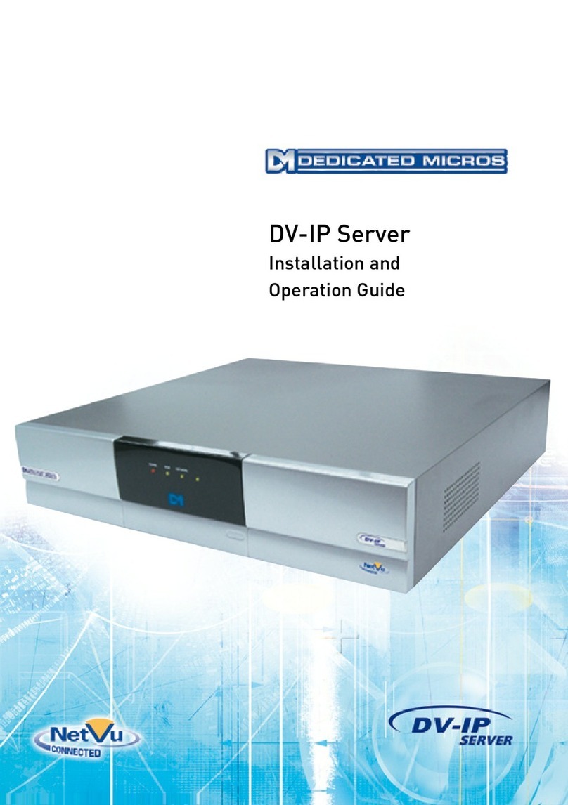
DV-IP Server
User Guide

Dedicated Micros ©2007
2
DV-IP Server User Guide
Contents
Introduction...................................................................... 3
Important Safeguards...................................................... 6
Quick Connection...........................................................11
Simple Conguration..................................................... 19
Appendix A .................................................................... 34
Appendix B – .ini Files................................................... 35
Appendix C – Port Assignment on the unit.................... 47
Appendix D – Unit Serial and Network Cables.............. 49
Appendix F – SMS Message Format ............................ 52
Additional Information................................................... 55
Index.............................................................................. 58
Whilst every attempt is made to ensure these manuals are accurate and current, Dedicated Micros reserve the right to alter or
modify the specication of the machine described herein without prejudice.
From Software No 04.4(029) M2IP-03.1 (09.2)

Dedicated Micros ©2007 3
DV-IP Server User Guide
Introduction
What is the…
DV-IP Server
The DV-IP Server has been designed to offer distributed monitoring and recording of multiple inputs.
Combining advanced hardware technology with numerous sophisticated viewing applications makes
the product range the ideal solution for many applications.
The DV-IP Server performs the task of a concentrator for analogue video, digitises, compresses,
stores and distributes these signals across an Ethernet network infrastructure. Supporting alarm
handling, on-board rewall for security, web conguration and monitoring, video motion detection
and much more making the Server a fully featured solution.
Remote monitoring of any site can be achieved via the Internet or a more sophisticated viewing
application can open up the extra features (remote alarm verication) supported on the Server.
Incorporating audio into the system allows a live bi-directional audio connection to be made between
the Sever and a Client application, as well as recording the audio along with the video on the Server
hard drive.
The unit is available as 6, 10 or 16 channel units, supporting JPEG and MPEG4 compression
ensures high quality video performance is maintained, and with the modular codec architecture
within the Server it is possible to achieve up to 120pps (NTSC) recording across all inputs
The local recording achieved with the DV-IP Server removes the issues found in many applications
where there are high bandwidth requirements for centralised recording. Supporting numerous
network protocols (IP, TCP, UDP, DHCP, FTP, TELNET, ICMP, HTTP, ARP) the DV-IP Server is an
ideal choice for a true converged network ensuring compatibility with new and existing network
infrastructure’s.
To further enhance the recording and monitoring capabilities external alarms and video motion
detection can be built-in to the system conguration to enable event recording and remote alarm
monitoring; an ideal scenario for Central Monitoring Stations.
The integration of numerous dome/PTZ protocols ensures that the DV-IP Server can be
retrotted into an existing system and offers no limitations for selecting compatible cameras when
incorporating into a new installation.
One of the unique features of the DV-IP Server is the On-board rewall supporting IP ltering and
TCP and UDP port allocation enhancing the security already achieved with the network rewall and
ensuring the unit can not be targeted when connected to a public network.

Dedicated Micros ©2007
4
DV-IP Server User Guide
Features
What does the DV-IP Server offer you?
Below is a list of the features that the DV-IP Server supports, take a look at this and see which
of these features is what your application needs, maybe this will highlight some features that you
hadn’t thought of but may be of value to the system you are installing, then using the How to….?
documents select the scenario to congure the unit.
• NetVu Connected
The DV-IP Server is part of the NetVu Connected family of DVR’s, Servers and software
offered by Dedicated Micros. This allows the DV-IP Server to be easily integrated into
any NetVu Connected system providing a system that can operate as a single unit or as
part of a system providing central monitoring capabilities for numerous sites.
• TransCoding Support
The DV-IP Server supports the option to record and view JPEG video images
alternatively it is possible to take the recorded JPEG and view this in MPEG4 format,
this feature ensures applications with bandwidth restrictions can still maintain the
highest quality video recordings but transmit at much lower bit rates maintaining
network efciency.
• MultiMode Support
MultiMode recording offers the ability to set different recording rates, resolutions and
compression across scheduled, normal and alarm modes, or to mix a standard setting
for many cameras with individual settings for particular cameras and time of day.
By varying the quality (bitrate) of the recorded image, users can increase recording
capability of the unit.
• Multi-camera Recording Server
Up to 16 cameras can be digitally recorded simultaneously. Using JPEG video
compression the high video quality is maintained.
• Multi Site Video Distributor
With the introduction of the Ethernet connection the DV-IP Server can distribute video
to any location on the LAN or WAN.
• Audio Control and Recording
The integration of bi-directional audio means that potential situations can be diverted,
help points can be incorporated into the overall solution.
Recording of the audio along side the video allows simultaneous playback showing and
hearing what happened during the incident.
• Multiple PTZ and Matrix Protocols
Allows the DV-IP Server to t into any application, retrot existing analogue systems;
incorporate a network connection by adding a DV-IP Server. This ensures that nothing
needs to be removed and discarded to achieve the functionality supported on the unit.
• Alarms and Relays
Integration of all Building Management means a single interface for monitoring the area;
door access alarm can trigger a camera to be recorded and transmitted to a monitoring
station.
Relays can be used to automatically trigger devices; lift barriers, open doors again
emphasises the possibilities of integration.
• Web Interface for Viewing and Conguration
No need to install dedicated software to connect to the Server, all congurations can
be carried out with a common interface for ease of use. Viewing is dependant on the
functionality required but simple viewing and control can be achieved via the web
interface.

Dedicated Micros ©2007 5
DV-IP Server User Guide
MPEG4 Compression
The unit includes MPEG4 image transmission capabilities. This technology ensures that users over
bandwidth constrained networks have the ability to view video in real time. It can record a mixture
of JPEG and MPEG on each video input and transmit either JPG or MPEG to each individual user.
Features are provided to ensure the user can congure the unit’s image resolution, bit rate and also
how many pictures will be transmitted. The unit is able to simultaneously serve JPEG images across
a LAN, transmit MPEG4 over a wide area connection, and record high quality JPEG images to disk.
Design of the manual
The DV-IP Server Setup manual is divided into sections to allow ease of installation and
conguration. The system works in a two tier scenario; simple and advanced features. This allows
the manuals to follow the same format, therefore offering:
• Simple installation
• Simple conguration
There is reference material on the accompanying CD to assist with the advanced features,
explaining how the functions operate and the advantage of each function to any installation.
The conguration section is designed to demonstrate typical scenarios and will guide you through
the conguration for all aspects of that scenario; How to allocate and IP address, How to enable the
Firewall feature, etc.
More information on the operation and control of the System is detailed in the Advanced DV-IP
Server User Guide on the CD.
CEMARK
If this product is marked with the CE symbol it indicates compliance with all applicable directives.
Directive 89/336/EEC.
A ‘Declaration of Conformity’ is held at Dedicated Micros Ltd.,
1200 Daresbury Park, Daresbury, Cheshire, WA4 4HS

Dedicated Micros ©2007
6
DV-IP Server User Guide
Important Safeguards
Read Instructions
All the safety and operating instructions should be read before the unit is operated.
Power Sources
This unit should be operated only from the type of power source indicated on the
manufacturer’s label.
Servicing
Do not attempt to service this unit yourself as opening or removing covers may expose
you to dangerous voltage or other hazards.
Refer all servicing to qualied service personnel.
Ventilation
Ensure unit is properly ventilated to protect from overheating.
All the safety and operating instructions should be read before the unit is operated.
To prevent re or shock hazard, do not expose this equipment to rain or moisture. The lightning ash
with arrowhead symbol within an equilateral triangle is intended to alert the user of this equipment
that there are dangerous voltages within the enclosure which may be of sufcient magnitude to
constitute a risk of electric shock.
Lightning Strike
The unit has some inbuilt protection for lightning strike, however it is recommended that isolation
transformers be tted to the system in areas where lightning is a common occurs.
Regulatory Notes and FCC and DOC Information
(USA and Canadian Models Only)
Warning: This equipment has been tested and found to comply with the limits for a Class A digital
device, pursuant to part 15 of the FCC rules. These limits are designed to provide reasonable
protection against harmful interference when the equipment is operated in a commercial
environment. This equipment generates, uses, and can radiate radio frequency energy and, if not
installed and used in accordance with the instruction manual, may cause harmful interference to
radio communications. Operation of this equipment in a residential area is likely to cause harmful
interference in which case the user will be required to correct the interference at their own expense.
If necessary, the user should consult the dealer or an experienced radio/television technician for
corrective action. The user may nd the following booklet prepared by the Federal Communications
Commission helpful: “How to Identify and Resolve Radio-TV Interference Problems”.
This booklet is available from the US Government Printing Ofce, Washington, DC20402, Stock No.
004-000-00345-4.
This reminder is provided to call the CCTV system installer’s attention to Art. 820-40 of the NEC that
provides guidelines for proper grounding and, in particular, species that the cable ground shall be
connected to the grounding system of the building, as close to the point of cable entry as practical.

Dedicated Micros ©2007 7
DV-IP Server User Guide
Installing the Unit
Simple Installation
Simple Installation is the minimum installation required for the unit for the unit to operate; we will
look at:
Installing the unit into a Rack/Shelf
Connecting Analogue video sources
Connecting the unit to the Network
Applying Power to the system
Tools Required
The tools required to install the unit to this stage are:
1 Suitable screw driver for or Allen key connecting the rack mounting kit and installing in
the rack
Note: The rack screws are not supplied by Dedicated Micros.
2 Rack mounting brackets (supplied)
3 Laptop running a terminal application, for example HyperTerminal™, see below for full
PC specication*
4 RS232 cross-over communication cable (Supplied and used for direct connection)
5 Power Supply (Supplied)
6 Mains cable (Supplied)
7 Ethernet cable (Can be connected directly via a hub or switch)
* Alternatively, a work station on the same DHCP enabled network as the unit can be used.
Choosing a location for installation
• The unit is designed to be shelf or desk mounted. The following precautions must be
taken during installation:
• Openings in the unit’s case are provided for ventilation. To prevent overheating, these
openings should not be blocked or covered.
• Ensure there is a 1” (2.54 cm) gap on either side of the unit.
• When stacking units, ensure there is at least a ½” (1.3 cm) gap between each unit.
• Ensure the unit is not located in an area where it is likely to be subjected to mechanical
shocks.
• The unit should be located in an area of low humidity and a minimum of dust. Avoid
places like damp basements or dusty hallways.
• If the unit is installed in a closed assembly, the maximum operating temperature must
not exceed 104°F (40°C).
• Ensure there is reliable earthing of the mains outlet when tted to supply connections,
other than direct connections, to the branch circuit.
• Any branch circuit supplying the unit must be rated 15Amps.
• It is recommended that an uninteruptable power source be connected to the unit in
case of power failure, to ensure continuous operation of the unit.
A quick overview of digital recording
Digital multiplex recorders work in exactly the same way as analogue multiplexers except that they
use hard disks to store video, instead of VCR tapes. Analogue recording uses time-lapse recording
to extend the length of time recorded onto 2 or 3-hour tape - recording fewer pictures every second.

Dedicated Micros ©2007
8
DV-IP Server User Guide
Adjusting the number of pictures recorded every second also extends the length of time recorded
onto the hard disk of a unit. However, other factors also determine the amount of time that can be
stored on the disk of a digital multiplex recorder:
The image quality
The record rate
The hard disk capacity
Image quality
Digital multiplex recorders store images in a compressed format, allowing images to be recorded
more efciently. The higher the compression, the smaller the le size, but the image quality will
suffer. The DVR offers a range of compression options and image storage formats to give the end
user the exibility to balance between image quality and storage capability.
Kilobytes and Gigabytes are units of storage, 1GB = 1000 Megabytes (MB) and 1MB = 1000
Kilobytes (KB), according to modern hard drive specications. (Now specied under SI units as
one kilobyte (1 kB) = 1000 bytes, whereas one kibibyte (1 KiB) = 1024 bytes to clear the confusion
caused by the term kilobyte simultaneously being used to refer to both 1,000 and 1,024 bytes)
With analogue recording, the image quality is dependent on the type of VCR being used; VHS or
S-VHS. The unit allows the image quality to be altered by adjusting the image size, for example, Low
quality is 14KB, Medium is 18KB, and High is 25KB.
Note: As for all digital recording, image quality can vary for different scene types, Medium quality
may be 18KB in one scene, but it may be 30KB or more to get the same quality in a scene
with more detail.
Using a larger image size will ll the hard disk faster than a smaller image size, as more space is
required to store it. To achieve the same amount of recording time when a larger image size is used
requires the record rate (PPS) to be reduced.
Standard record rate
The record rate is the amount of pictures recorded to disk in a second, or pictures per second (PPS).
This is a system wide gure and is not effected by how many cameras are connected. The update
rate per camera can be worked out using the record rate:
Update rate = No. of cameras/Record rate
MultiMode Recording
MultiMode recording offers the ability to set different recording rates, resolutions and compression
across scheduled, normal and alarm modes, or to mix a standard setting for many cameras with
individual settings for particular cameras and time of day. By varying the quality (bitrate) of the
recorded image, users can increase recording capability of the unit.
MultiMode recording offers:
Ability to set different recording resolutions including 704x512, 704x256, 352x256 and 176x128.
Ability to set MPEG or JPEG compression recording.
Ability to set PPS recording rates.
Dynamically switchable resolution when switching from Normal to Event Recording.
Dynamically switchable compression between MPEG4/JPEG from Normal to Event Recording.
Rear Panel connections
The illustration shows the rear panel connections.

Dedicated Micros ©2007 9
DV-IP Server User Guide
SERIAL 2
NET
SCSI
SERIAL 1
AUDIO 1
IN
OUT
IN
AUDIO 2
OUT
SERIAL 3
VID 14
AUX ALARMS485 BUS
VID 3VID 1MON
B
A
VID 2
3
TERM
SERIAL 4
1 2 54
VID 4 VID 5 VID 6 VID 10VID 7 VID 8 VID 9
AUX RELAYS
VID 12VID 11 VID 13 VID 15 VID 16MON A
(BUS A) (BUS B)
Video
VID1 to VID16 75Ω BNC composite camera connections, 1V pk-pk with loop
through, unit is available as a 10 or 16 channel unit
MON A Not currently used, available for future expansion
MON B 75 Ohms BNC composite monitor output, 1V pk-pk
MON A Not currently used available for future expansion
Audio
AUDIO 1 IN RCA (phono) socket, 22KHZ sampling, 47 KΩ input impedance.
AUDIO 1 OUT RCA (phono) socket.
AUDIO 2 IN RCA (phono) socket.
AUDIO 2 OUT RCA (phono) socket.
Data
SCSI 50-pin HD SCSI-2 connection.
NET RJ-45 100-baseT Ethernet connection.
SERIAL 1 & 2 9-way (Male) D-type RS-232 serial port
SERIAL 3 & 4 (BUS A & BUS B) 9-way (Male) D-type RS-232, RS-422 and RS-485 serial port.
TERM Termination DIP switches for RS-485.
485 BUS 2x MMJ ports for DM 485-BUS accessories.
Alarms and relays
R1 Screw terminal, alarm relay dry contact, NO/NC, congurable for
alarm.
R2 Screw terminal, activity relay dry contact, NO/NC, congurable for
VMD.
DIRECT Screw terminal, direct auxiliary input, NO/NC.
AUX ALARMS 25-way (Female) D-type programmable alarms, NO/NC.
AUX RELAYS 9-way (Female) D-type, congurable for global camera fail and
trigger on alarm.

Dedicated Micros ©2007
10
DV-IP Server User Guide
Front Panel
LED’s
Power The power LED will be green to indicate power is connected to
the video server
HDD Hard Disk Drive This will ash when images are being stored to the hard disk
Network The Network LED will be green to indicate a connection
IR Not currently used available for future expansion

Dedicated Micros ©2007 11
DV-IP Server User Guide
Quick Connection
Recommended PC Specication
The following is the recommended PC specication to allow conguration and viewing of the unit
using a browser interface and also viewing and control from the NetVu ObserVer application:
Minimum Recommended
Operating System Window 2000 Windows XP Pro
Processor 1GHz Intel Pentium 3 2GHz Intel Pentium 4
or equivalent or equivalent
System RAM 512MB 1024MB
Screen Resolution 800 x 600* 1024x 768 or higher*
Colour Depth 24bit* 24bit or 32bit*
Browser Internet Explorer 6
Netscape Navigator 7.1
Firefox 1.5
JRE J2SE Runtime Environment 5.0 Update 4
* Although the system will operate on lower specication computers the above is
recommended to provide high performance video quality and update rates. If lower
specication processors are used this could affect the overall performance of the computer
WARNING: For a web browser to correctly operate with unit, Java Virtual Machine (JVM) which is
contained in the Java Runtime Environment (JRE) must be installed on each PC that will
be used to access unit. The JVM enables Java components in web pages to operate as
intended by Dedicated Micros. A version of Java Runtime Environment may be downloaded
from http://java.sun.com
The Java Virtual Machine is one aspect of Java software used in web interaction. The Java Virtual
Machine is built into the Java software download, and helps the Sun JRE run Java applications.
Administration rights will be required to install JRE onto a Windows 2000 or Windows XP machine.
The JRE can be loaded using one of three methods, Automatic, Manual or Ofine.
Automatic installation will require the machine stays connected to the internet whilst the software is
loaded directly from the web. This method requires no user intervention.
Manual installation downloads a small program from the web, which will fetch the required les from
the web when it is run. It offers more control over the installed options than the Automatic method.
Ofine installation will download all the required les onto the computer before commencing
installation. This le can then be run when the computer is not connected to the internet, and copied
onto other machines without internet access, if necessary.
The software on the unit is written for the Sun Java Machine, and the Microsoft Java Machine should
be disabled for optimum reliability.
You can switch between the Sun Java Virtual Machine and the Microsoft VM. The Sun JVM can be
enabled and disabled without having to uninstall it. Switching back and forth between these Virtual
Machines can be done through the Advanced tab in your Windows Internet Options Control Panel,
OR by using the Java Control Panel.
Note: It is good practice to check both locations.
To switch between the Sun JVM and Microsoft VM using Internet Options:
1 Open Control Panel by clicking Start->Settings->Control Panel
2 Open the Internet Options window by double clicking Internet Options
3 Click the Advanced Tab
4 Find the “Java (Sun)” item and check or uncheck the checkbox which says “Use Java 2
v 1.4.x for applet (requires restart)”

Dedicated Micros ©2007
12
DV-IP Server User Guide
5 Check or uncheck the box next to Microsoft VM
6 Save your changes by clicking the OK button
7 Restart the browse
Instructions for switching between the Sun JVM and Microsoft VM using the Java
Control Panel:
1 Open the Windows Control Panel by clicking Start->Settings->Control Panel
2 Open the Java Control Panel by double clicking the icon labeled “Java Plug-in”
3 In the Java Control Panel, click the Browser Tab
4 Under the Browser Tab you will see checkboxes next to installed Web browsers.
5 Check or uncheck the checkbox next to the Web browser you want enable or disable
from using the Sun JVM
6 Click the Apply button to save your settings
7 Restart Internet Explorer
Tools Required
The tools required to install the unit:
Item Description
1 Suitable screw driver for mounting the unit in place
2 Wall-mounting brackets (supplied)
3 Laptop connected to the same network as the unit
4 Power Supply (supplied)
5 Mains cable (supplied)
6 Ethernet cable
Note: The rack screws are not supplied by Dedicated Micros.
Connecting the Rack Mounting Brackets
Please note the unit is heavy. Always follow health and safety guidelines when lifting the unit from
the box or installing the unit. When rack mounting the unit it is important that both the front and rear
brackets are installed to correctly support the unit in the rack, failure to do this may result in damage
of the unit.
A rack mounting kit is supplied with this product, it is important to install this correctly. The kit
comprises of:
4 x Rack mount screws
2 x Rear supports
2 x Front Rack mount ears
Before connecting any cables to the unit connect the rack mounting kit:

Dedicated Micros ©2007 13
DV-IP Server User Guide
• Attach the rear supports to the rack that the unit will sit in, these will support the weight of the unit.
• Using the supplied screws, attach the rack mount ears to each side of the unit.
• Position the unit on the rear supports.
• Attach the rack mount ears to the front of the rack.
Connecting Video Sources
The unit is available as 6, 10 or 16 channel units; the rear panel in this section shows a 16 channel
unit, the only change between units is the number of video inputs; all other connections are the
same.
The video inputs are 75 ohm BNC connector’s and require a 1 Volt peak-to-peak video signal.
There are two rows of connectors which provide video input and loop through support. It is possible
to connect the video input to either the top or bottom row of BNC’s.
However it is important to ensure connection consistency for quality of installation by selecting one
of the rows as the video input and the other as the loop through connection.
Note: It is recommended that you connect the cameras from the lowest number rst; however it is
possible to disable inputs in the unit conguration pages.
Connecting to the Network
The unit supports a 10/100Mbps auto detecting Ethernet Network Interface Card. The purpose of
the network interface is to support the remote conguration, monitoring and control of the unit over a
network connection.
NET
SERIAL
AUDIO
IN
OUT
BUS
VID 3
VID1
MON
B
A
VID2 VI
MONA
Using a straight-through network cable (Appendix A) connect to the NET socket on the unit to a port
on the network. The unit is shipped enabled for DHCP network. An IP Address will be automatically
allocated when the unit is powered up, and will be displayed on a connected spot monitor for a user
dened period (initially set as 10 minutes).
Note: Although the unit is automatically allocated an IP address, it is recommended that a static IP
address be congured on the unit.
Note: The Spot monitor needs to sync with one connected camera to display the IP address
correctly. If no cameras are connected, the IP address will not display correctly.

Dedicated Micros ©2007
14
DV-IP Server User Guide
Connecting serial devices
The unit supports four serial (communication) ports. Each port can be congured to support various
peripheral devices.
By default Serial 1 is enabled for Debug (Engineering mode) allowing you to connect and congure
the unit.
All COM ports are 9 Way D-type male connector’s with the following pin connections for RS232,
RS422 and RS485.
RS422 Connectivity
Pin SERIAL 3 SERIAL 4
1 Transmit Data (TX+) Transmit Data (TX+)
4 Receive Data (RX-) Receive Data (RX-)
6 Receive Data (RX+) Receive Data (RX+)
9 Transmit Data (TX-) Transmit Data (TX-)
RS485 Connectivity
Pin SERIAL 3 SERIAL 4
1 Transmit Data (TX+) Transmit Data (TX+)
9 Transmit Data (TX-) Transmit Data (TX-)
RS232 Connectivity
Pin Description SERIAL 1 SERIAL 2 SERIAL 3 SERIAL 4
1 Data Carrier Detect DCD DCD
2 Receive Data RX RX RX RX
3 Transmit Data TX TX TX TX
4 Data Terminal Ready DTR DTR
5 Ground GND GND GND GND
6 Data Set Ready DSR DSR
7 Ready to Send RTS RTS RTS RTS
8 Clear to Send CTS CTS CTS CTS
9 Ring Indicate RI RI
Termination Dip Switches
Part of the installation process for the communication ports is to ensure the termination is correctly
set on each port.
The communication ports support RS232, RS422 or RS485 serial data. When connecting to RS422
or RS485 devices the corresponding DIP switches on the rear of the unit must be set for termination,
the following details the correct conguration.

Dedicated Micros ©2007 15
DV-IP Server User Guide
12345
ON
SW1
SW2
SW3
SW4
SW5
DM 485 Bu s
SERIAL 3 RS485 termination (TX)
SERIAL 3 RS422 termination (RX)
SERIAL 4 RS485 termination (TX)
SERIAL 4 RS422 termination (RX)
Connecting Power
If there are no further installation requirements (audio, alarms, etc), the unit can be powered up at
this stage.
The unit is congured for DHCP and will be automatically allocated an IP Address if connected to a
DHCP network. The unit supports an internal power supply and connects directly to the mains.
To connect power to the unit:
1. Ensure the mains is switched off at the socket
2. Connect the main power lead (supplied with the unit) to the POWER connector on the
unit, ensure you follow Health and Safety procedures.
VID 14
0 VID 12
VID 11 VID 13 VID15 VID 16
3. Switch the mains on at the socket
4. Check the Green LED on the front panel of the unit lights to show the unit has powered
up successfully.
5. If the network supports DHCP, the IP address will be displayed on the spot monitor
during boot.
Conguring the IP address via the web pages
It is possible to congure the network information using the onboard web pages, providing the IP
Address allocated by the DHCP server was noted.
Note: The unit IP address will be displayed on the Spot monitor for approximately ten minutes
after boot.
1. Launch the web browser (Internet Explorer, Netscape Navigator or FIrefox)
2. Type the IP address of the unit into the address bar
3. You will be presented with the Main Menu page
4. Select Conguration Options. You will be prompted for a username and password. The
default settings are dm and web respectively.
4. Select Network -> Network Settings
2. The IP address, subnet mask and default gateway allocated by the DHCP Server will
be displayed on this page. These can all be edited
The unit now has been installed for simple operation.

Dedicated Micros ©2007
16
DV-IP Server User Guide
Setting and Enabling Passwords
There are a number of features supported on the unit that can be password protected to prevent any
unauthorised access, these are:
Webpage Conguration
Telnet
FTP
These are congured within the relevant web pages.
Default Passwords
The unit has the following default user names and passwords; it is recommended that these default
settings be changed as soon as possible to ensure security.
These functions can all be accessed via the onboard web pages.
Webpage Conguration : Username = dm password = web
Video FTP : Username = dm password = ftp
FTP Admin : Username = dmftp password = ftp
Telnet : Username = dm password = telnet
Note: Ensure you make note of the new usernames and passwords that are congured, loss of
this information will require the unit to be returned to Dedicated Micros for password reset.
Note: Avoid using non alpha-numeric characters when selecting a password, as these can be
misinterpreted by the system (Use a-z and 0-9). However underscores, full stops, question marks
and hyphens ( _ . ? - ) are safe to use within passwords.
ALLOCATINGANIPADDRESS

Dedicated Micros ©2007 17
DV-IP Server User Guide
Network Conguration
This manual is designed to help with the advanced conguration of the unit using the on-board web
pages.
To assist with the conguration of the unit, sections are constructed as tutorials and will illustrate
how to perform common requirements. Use the tutorials that will provide the required functionality
and follow the step by step instructions.
This manual will cover simple conguration –required to get the unit up and running
Advanced Conguration is available in the manual available on the accompanying CD.
Note: The unit should be congured in line with the main conguration steps detailed in the Setup
Guide and therefore the cameras inputs have been enabled and the standard record rate
has been set.
Web Page Icons
Each of the unit conguration web pages has the following buttons:
Reset to Defaults –This will return the associated page to factory defaults.
Display Help –This will display the Help pages for the associated conguration page. This is a good
starting point if you are having problems or do not understand the conguration parameters.
the Save Settings icon –This will save a changes that has been made to the conguration page
- remember to save the changes.
NOTE: Selecting a new page before saving the changes will result in any changes being lost!
Reset –This is displayed on conguration pages that require a unit reset to initiate a function.
Note: Always save the settings before resetting the unit.
Each ‘How to.. Section’ will show the Tab and Function name to allow easy location of the correct
conguration page.

Dedicated Micros ©2007
18
DV-IP Server User Guide
Accessing the Conguration Web Pages
The unit is congured using on the on-board web pages. To access these:
Note: The unit should already have been congured with an IP address (via the serial port) and
connected to an Ethernet network.
1. Launch Internet Explorer (or Netscape Navigator).
2. Type the IP address of the unit into the address bar.
3. The Main Menu page will be displayed.
4. Select Conguration Options. The unit will prompt for a username and password. The
default settings are dm and web respectively.
Note: The user name and password are case sensitive; they should be changed from the default
username and password and kept safe. Mislaid usernames and passwords could result in
the unit being returned to Dedicated Micros for reseting.
Main Menu
The Main Menu allows the Operator access to:
Live viewing of any of the connected cameras.
Conguration web pages for the unit.
Downloads which include the software applications and the product documentation.
Demo pages that demonstrate how viewing applications can be designed for varying
system requirements.

Dedicated Micros ©2007 19
DV-IP Server User Guide
Simple Conguration
How to Congure Global Parameters
There are some parameters that can be set that will affect the overall system; video standard for the
video inputs, browser format for the web interface, language that the menus will be displayed in and
the DST (daylight saving time) settings.
To congure global parameters:
1. Select Home -> Main Set-up.
2. The Video Standard shown will be the standard for all the video inputs on the unit.
Note: It is necessary to carry out a system reset if the video format is changed before saving the
settings. This allows the unit to activate the change.
3. Select the preferred date format from the drop down list.
4. The unit web pages can be viewed in two formats; ActiveX (default) or Java, select the
relevant option from the drop down list.
5. The web conguration pages for the unit can be displayed in a selection of languages,
select the language which is most appropriate to your installation from the drop down list
.
Note: Ensure the PC being used for the conguration is set to the correct time zone and that DST
is enabled before continuing.
6. Select the DST for region where the unit is installed from the drop down list.
7. If the settings are incorrect reset the unit by selecting the reset button.
8. The Unit time can be synchronised to the PC being used to congure the system. This
will set the time on the DVR when the ‘Sync Unit time from PC’ button is pressed, it will
not maintain synchronisation between the two.
9. Remember to save the conguration by clicking the Save Settings icon!
Function Description
Video Standard This displays the setting for all the video inputs on the unit.
Date Format It is possible to identify the format in which the date will be
displayed; the default setting is Day Day, Month Month, Year Year.
Browser Settings The browser interface on the unit supports ActiveX or Java, select
the most appropriate for the application from the drop down list. All
users connecting to the system will be presented with the selected
interface.

Dedicated Micros ©2007
20
DV-IP Server User Guide
Language The unit web conguration pages can be displayed in the
language that is most suitable to the country of installation. The
currently supported languages include; English, Spanish, French,
Czech, Italian, Russian, Dutch, Portuguese, German, Turkish,
Croatian, Danish, Finnish, Norwegian, Hungarian, Swedish,
Polish, Arabic, Chinese
DST (Daylight Saving Time) This reects the local time zone for the area where the unit is
installed.
Reset This will reset the unit.
Sync Unit time from PC The unit can be synchronised with the PC that is being used to
congure the unit. The synchronisation is not persistent and will
only synchronise the unit and the PC at the time the button is
pressed.
How to Enable System Features
There are a number of features supported on the unit that can be enabled or disabled depending on
your system requirements.
When these features are enabled, the relevant conguration web pages will be displayed; if these
are disabled then these pages will be omitted.
To enable the features;
1. Select the System -> Advanced Features.
2. By default the Live options are enabled. To enable any other required features, tick the
box next to the feature.
3. Remember to select the Save Settings icon!
4. Click �Reload Webpages’ so the relevant conguration pages for the enabled featuresClick �Reload Webpages’ so the relevant conguration pages for the enabled features so the relevant conguration pages for the enabled features
can be displayed.
5. Some features will require a system reset. If the required page is not available after
reloading, press the Reset button to reset the unit and re-load the web pages.
Other manuals for DV-IP
3
Table of contents
Other Dedicated Micros Server manuals

