Deekax FAIR-80 EC User manual

1
THE QUALITY GOALS OF AIR CONDITIONING COME TRUE WITH THE
RECOVERY SYSTEM
Air ventilation system TALTERI is designed to remove stale air from the interior and
supply it with fresh and clean air.
Humidity and impurities are exhausted through the thermal recovery unit that cost-
effectively heats the filtered ambient air. Fresh warm air is channeled draught-proof
and noise-free into the premises in necessary quantities.
ENSURE THE QALITY OF AIR EXCHANGE!
QUALITY CONTROLLED
HEAT RECOVERY VENTILATOR FAIR-80 EC
INSTALLATION AND USER MANUAL
2
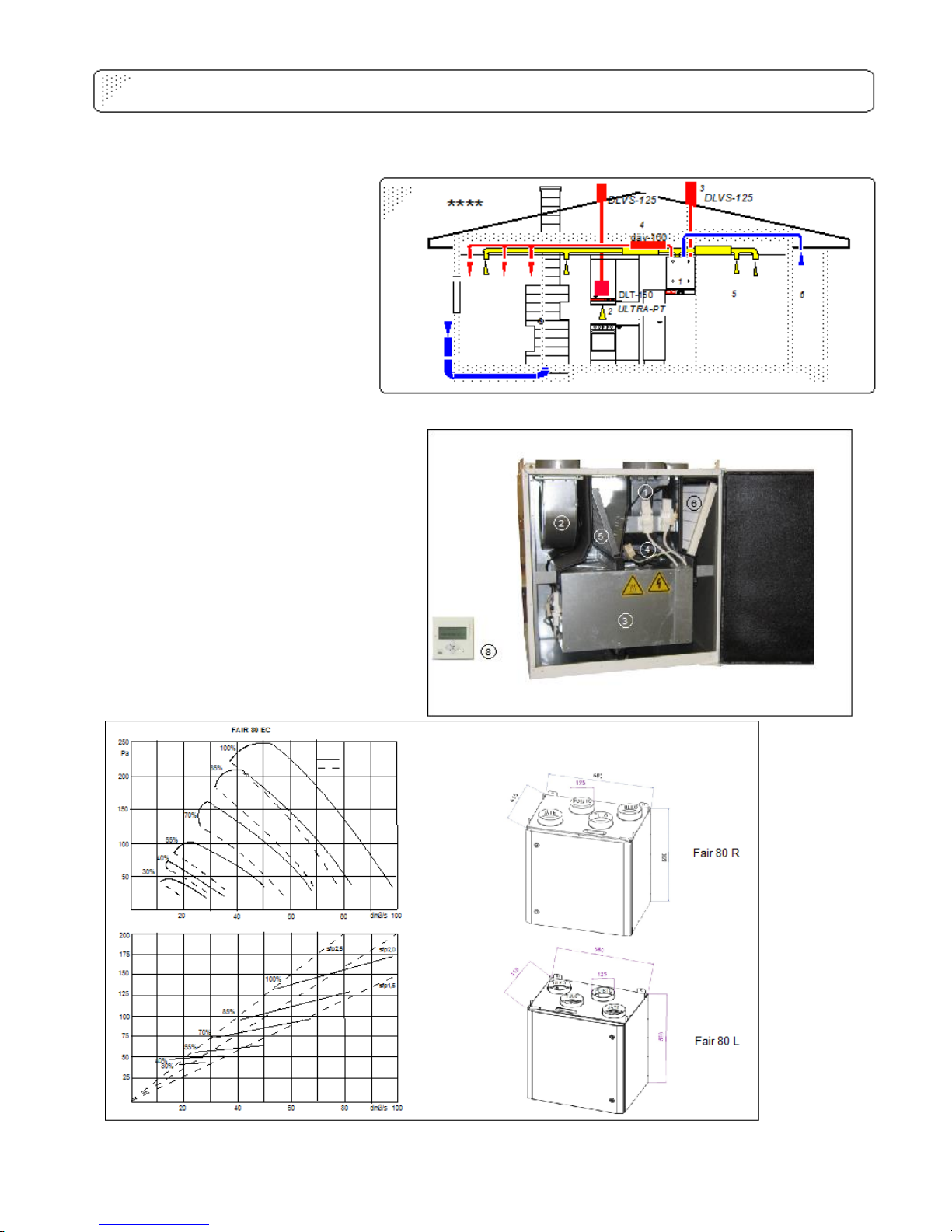
TALTERI HEAT RECOVERY AIR VENTILATION SYSTEM
Picture 1:system components
OUTDOOR AIR
EXTRACT
AIR
SUPPLY
AIR
EXHAUST AIR
BED
ROOM
LIVING
ROOM
OVEN
KITCHEN
UTILITY
ROOM
WALK-
IN CLO-
SET
BATH
ROOM
SYSTEM COMPONENTS
Picture 1
1. Heat recovery ventilator (HRV)… FAIR-80 EC
2. Exhaust fan hood……… DX-ULTRA-PT
Exhaust hood……………. DLT-150
3. Exhaust air outlet………DLVS-125
4. Duct silencer…………….. Ø 125
5. Extract air to the heat recovery
ventilator …………………. .Ø 125
6. Fresh air intake from outdoors Ø125
7. Fresh air supply to the rooms Ø125
MACHINE PARTS AND TECHNICAL DATA
Duct connections
4 pcs, outer connection Ø 125mm
1. Supply fan EC 119 W
2. Exhaust fan EC 119 W
3. Rotating heat exchanger
4. Adjustable post-heating element…800W
5. Exhaust air filter ….G4
6. Supply air filter ……G7
7. Drain in the bottom
(1/4”internal thread )
8. Control panel
Total power consumption W
Total pressure Pa
Picture 2:right handed(R) model of HRV FAIR
Air flow
Air flow
Exhaust air
Supply
air
Dimensions: height 590mm, width
580mm, depth 415 mm , weight 52 kg
Picture 3: pressure and power consumption vs air flow
3
1. Installation
1.1 General installation instructions
Heat Recovery Ventilator 'Fair' (here in after –HRV) should be installed in a warm premises, with indoor
temperature over +5 °C.Ventilation ducts should be spacious enough so that the velocity of air streams is
sufficiently low. The duct size is to be determined according to the size of the ventilated apartment and the
forecasted air consumption.
National Building Code of Finland (chapter D2) contain regulations and guidelines for indoor climate and
ventilation of buildings, airflow planning and ducts recommendations, and terminal design and placement.
Chapter C2 of the above mentioned National Building Code contains regulations and guidelines for moisture
technical planning. National Building Code of Finland are freely available on the Ministry of Environment
website (http://www.ym.fi/en-US).
Space sufficient to open an HRV door should be taken into account when planning suitable place for HRV
installation. The electric socket should be located near the HRV device to make electricity connection
conveniently available.
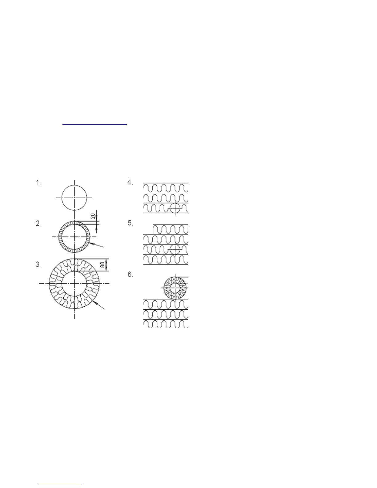
1.2 Isolation of ducts
Example of different types of insulation:
1. An extract air duct in the warm premises.
2. A supply air duct from HRV to the valve.
3.An exhaust and outdoor air ducts installed indoors (warm space).
4. An extract air duct inside the insulation material of the room's ceiling installed above the vapor barrier
5. and 6. any type of duct installed in the cold space(e.g. in the attic)
Note! Outdoor or exhaust air ducts shall not be installed on the vapor barrier directly, but must be insulated
with not less than 100 mm thick insulation material.
Vaporproof
outer surface
Vaporproof
outer surface
Picture 4:isolation of ducts
4
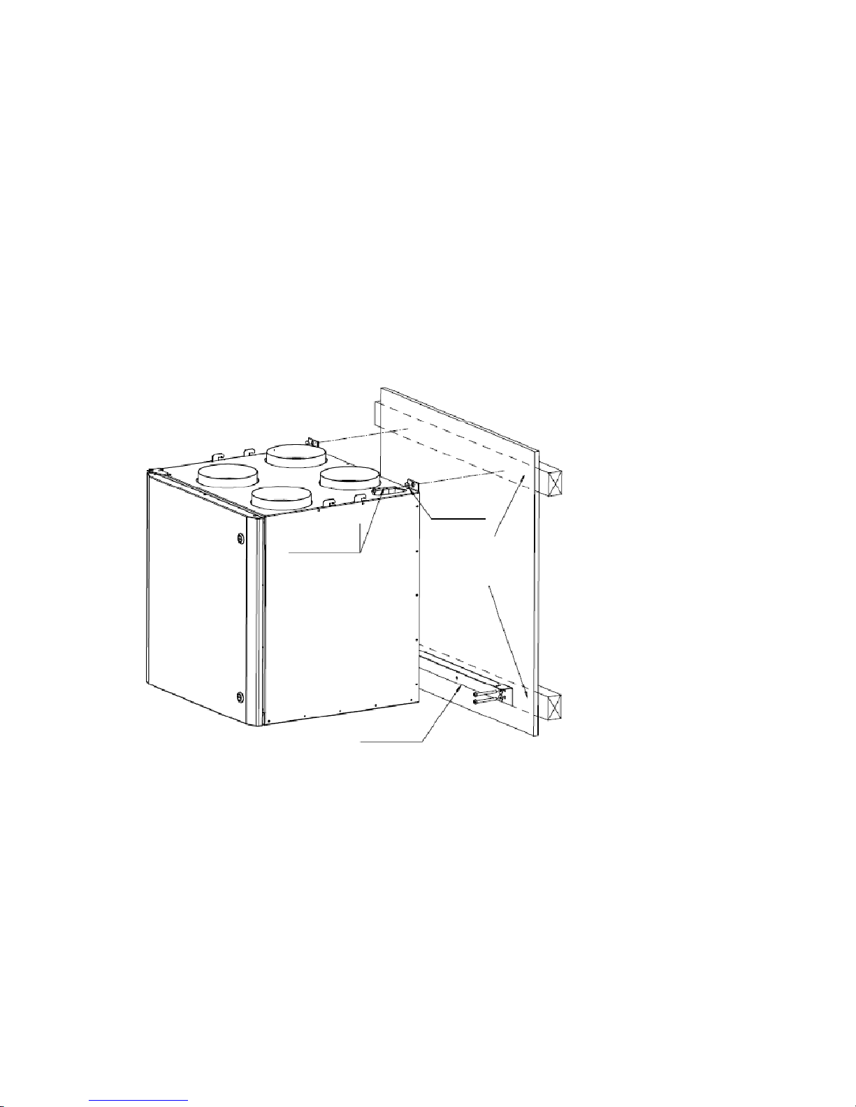
1.3 Mounting on the wall
The standard model of HRV includes mounting brackets to ensure easy and secure mounting of the device
to the wall. Low noise operation of HRV can be achieved by avoiding of its installation on bedroom walls,
hollow or resonating walls.
It is advisable to install HRV on the load-bearing walls whenever possible. If installation of HRV on the load-
bearing wall is not possible, use, for example, a plywood sheet between the HRV and the non-bearing
wall.
Installation steps
1. Mount the lower bracket on the wall, pay attention to the correct height of installation and whether the
chosen wall is load-bearing.
2. Lift and set the device on the lower mounting brackets; this will also facilitate the installation process.
3. Fasten the upper mounting screws, note the structure of the wall (differs for load-bearing and non-bearing
walls as noted above)
Mounted HRV should be slightly reclined backwards to ensure drainage of possible condensed water. The
rear side of the HRV bottom should be at least 2 mm lower than the front side. Reclining can be done during
the installation by moving the backside slightly downwards, the oval-shaped holes of the brackets allow to
do the adjustment.
Picture 5:installation of ’FAIR’ HRV
washer
sufficiently long
and sturdy screw
lower bracket
Behind the gypsum wall in the
mounting points there must be a
supporting frame.
Picture 5:installation of ’FAIR’ HRV

5
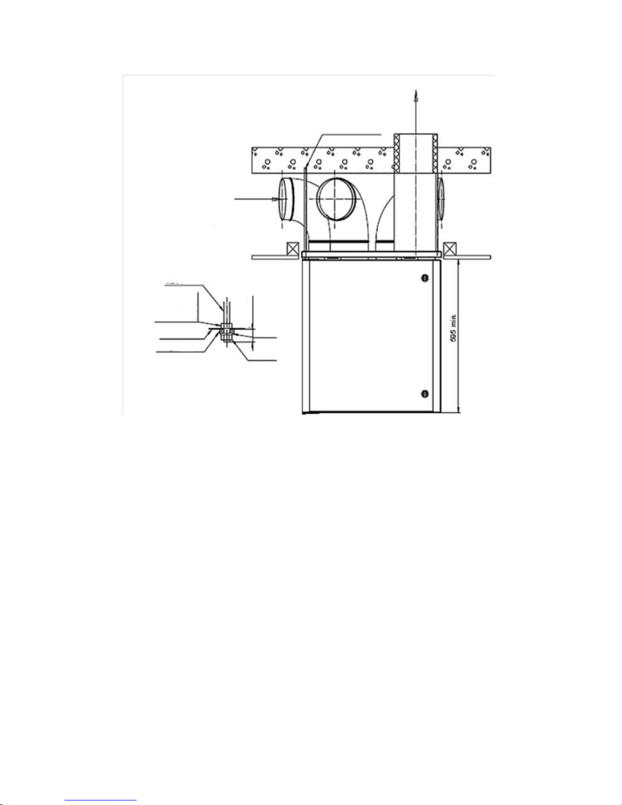
Mounting with the ceiling mounting plate(optional)
In case of installation of HRV to the ceiling, ducts can be installed in advance and secured with special
supporting components. Ceiling finishing works can be done before final installation of HRV.
The ceiling mounting bracket is usually fastened to the ceiling with four 8 mm threaded rods. Sound-
absorbing rubber gaskets should be used with the threaded rods for sound and vibration dampening. One
of advantages of such threaded rod installation is prevention of sound propagation to ceiling. However, if
necessary, ceiling mounting bracket can be also connected directly to the ceiling.
While installing the HRV drainage of the condensate should be taken into account: the HRV should be
reclined slightly backwards. The backside of the HRV bottom must be at least two millimeters lower than its
front side.
Steam barrier installation
When installing a steam barrier it is advisable to use the ceiling mounting bracket as an aid. Size of holes
punched in the steam barrier tape should be little smaller than the diameter of the duct holes on the ceiling
mounting plate.
When lifting up the ceiling mounting plate to it’s place, press the steam barrier tape against the top surface
of the mounting plate and use adhesive tape if necessary to ensure tight installation.
The steam barrier plastic tape can be sealed carefully to the edges of the mounting plate with adhesive
tape.
'FAIR' HRV are also available with a rubber plate which makes sealing of the steam barrier easier.
Liftning up the unit
1. Set the cellular plastic rings around the outlet ducts.
Prior to installation the heat exchanger can be
demounted from the HRV in order to reduce the weight
and make the installation easier. Additionally, the HRV
door can be removed as well by removing the hex m6
bolt from the bottom hinge.
2. Lift the HRV carefully towards the ceiling mounting
plate. Align the hooks placed on the side of the HRV
towards the slots on the ceiling mounting plate. Lift HRV
upwards till the hooks lock up to their first position.
3. Make sure that the cellular plastic rings have
remained on their places after the installation and the
electrical wiring passes freely, and there are not extra
objects inside the unit.
4. Applying more force lift the unit up in order to lock up
the both hooks of the HRV.
5. Make sure that the cellular plastic rings are tightly
fastened against the ceiling mounting plate and lock the
fastening with the two screws supplied.
6. Make sure that the HRV is declined enough in order
to lead the condensing water out of the unit.
Attention! For the right handed model( FAIR 80 R) the ducts are located as mirror image.
Electrica
l cable
pass-
through
Locking with
two screws
after the
installation
Fasting
points for the
ceiling
mounting
The cellular
plastic rings are
set around the air
ducts.
The hooks for the
ceiling mounting plate
Picture 6: ceiling mounting. (FAIR -80 L)
6
.
1.5 Condensation drainage HRV 'FAIR' is equipped with a drain equipped with a plug. Depending on the
humidity of the apartment condensation may occur in some situations inside the HRV and, therefore, it is
advisable to lead the condensate through the drain (1/4'' in-thread) into the nearest floor drain or sink basin.
Condensation water pipe should not be connected directly into the sewerage without a water trap. The water
trap should be installed directly on the bottom of the HRV. Recommended water level in the water trap
should be 100 mm.
When the HRV maintenance work is done, it should be checked that there is enough water in the water
trap. Add more water if needed.
1.6 Introduction
Before using the machine, make sure that
- the device is installed according to these instructions and connected to the ductwork according to HVAC
plan.
-the filters are in their places and there are no extra items inside the device..
- the control panel is connected to the device.
Note! Don’t switch the unit on if the service hatch is open.
8mm threaded rods
Exhaust air
(the duct is isolated)
Outdoor air
M8 threaded rod
M8 nut holds the mounting plate
steady when the unit is lifted up
ceiling mounting plate
rubber cushion or sleeve
washer
m
ax
25
m
m
8 mm nut
Picture 7: ceiling mounting example
7
8
9
2 Operation
2.1 General information
For proper ventilation of the apartment it is extremely important that the HRV and the ducts system are
installed and configured professionally and accurately. The HRV must be equipped with clean filters on the
configuration phase and the data terminal equipment of the ductwork must be placed properly, including
installation of the outer grill.
The exhaust air consumption should be ever about 5- 10% higher i than consumption of the supply air. It
will keep an apartment slightly underinflated and prevent excess humidity.
The ventilation unit must always run on the power which is high enough to keep the moisture level of the
apartment within standard limits. If humidity level in winter is too high, it will cause appearing of the
condensate on the cold windows. Recommended air humidity level is 40 - 45% at normal room temperature
(20-22°C).
It is important to change the filters often enough to maintain good indoor air quality and to secure the
operation of the unit. Clogged filters weaken the HRV power significantly and, therefore, reduce the airflow
and increase the noise level.
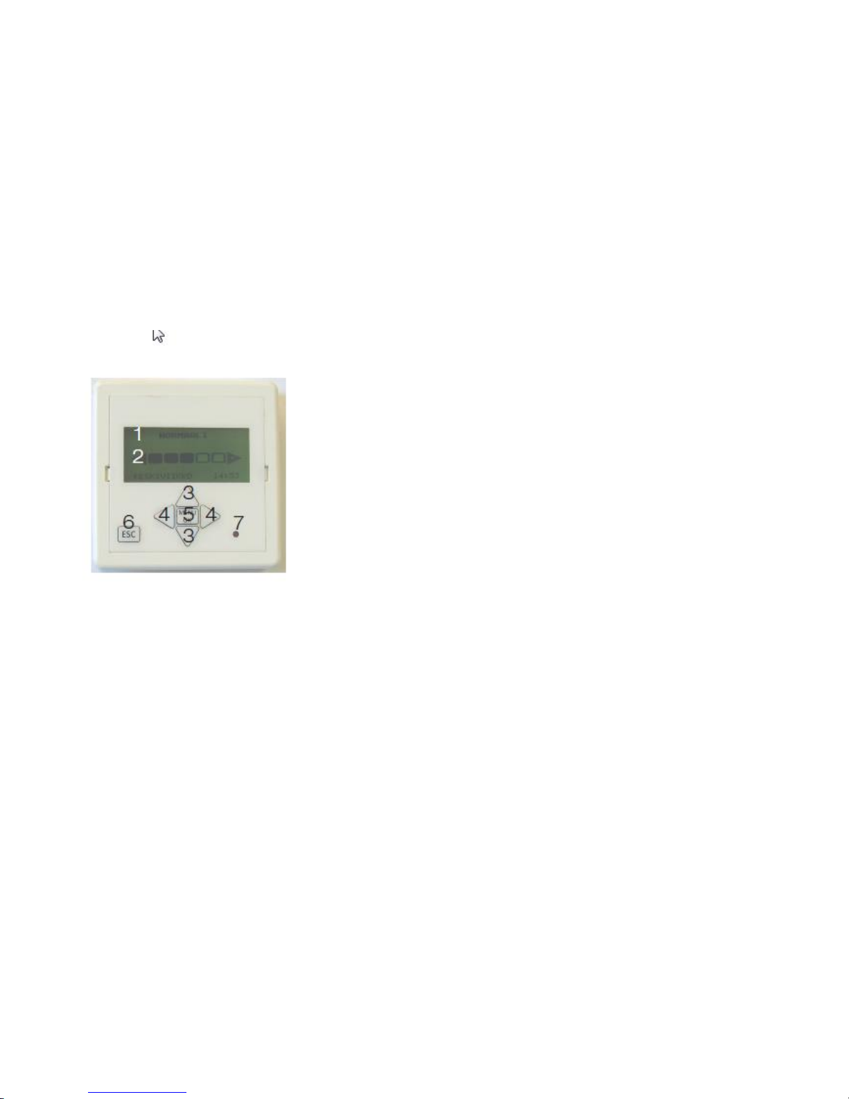
1. Unit's status
2. Fan speed
3. Search menu
4. Fan speed selection
5. Selection of the value
6. Return
7. Alarm light
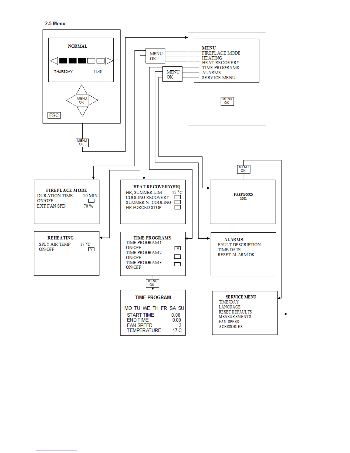
2.2 Basic functions of the control system
After the HRV is connected to the electricity circuit, the exhaust fan starts operating at the normal speed and
the heat exchanger works normally. During startup text “Start” is shown on the display in the speed data
sector. Speed controls are disabled for the startup time. After 30 seconds delay the HRV switches to the
normal speed and can be controlled from the control panel.
The fan speed of the ventilation unit can be adjusted normally with buttons of the control panel. There are
five following modes available:
Min
Unoccupied
Normal
Boost
Cooling
The above-mentioned names of the speed modes are shown on the control panel above the speed indicator
bar. The fan speeds corresponding to above-mentioned modes are set through the "Fan speed " item of the
maintenance menu during initial installation
(password of the maintenance menu is 1001). The rotation speed setting can be chosen for each fan
individually within 0-100% intervals.
Attention! Note the speed settings of the supply and the exhaust fan configured during initial
installation; refer to the maintenance records table.
Picture 8:control panel

10
Timers
Three different time programs can be configured for this HRV. When the timer is set, HRV operates with
predefined fan speed and the supply air temperature is controlled according to the predefined value.
Fireplace function
The fireplace function is controlled through "Fireplace Mode" item of the control panel menu. Time of this
function can be set as follows: Service menu->Accessories->Fireplace mode. This mode can be active for
5-60 min; time can be adjusted with five minutes steps.
The fireplace mode can also be disabled through the same service menu. In this case the lock symbol will
be displayed in the ”Fireplace mode” menu and this menu item will be disabled.
In the Fireplace mode the supply fan is operating at the chosen speed and the speed of the exhaust fan is
adjusted according to the percentage value. Text “Fireplace mode” is shown on the display in the speed
data sector.
Fireplace mode can not be switched on if the HRV is operating in the defrosting mode.
Measurements
The values of all sensors and the transmitters can be checked through the ''Measurements' item on the
Service menu. One value at the time can be chosen for displaying on the home screen of the control panel
if HRV operates in the normal mode.
Key lock
By pressing buttons ^ and v simultaneously and holding them for 2 seconds, display's keyboard will be
locked; and a lock symbol will be shown on the display. The key lock is released by pressing the
same buttons and holding them for 2 seconds until the lock symbol disappears.
After-heating
Ventilation unit FAIR-80 has an 800 W electric post-heating element , which heats the supply air if needed.
When this function is activated, the air temperature is regulated as precise as possible according to the set
value (13-22 ° C). When the supply air is heated by the heating coil, symbol is shown on the display.
Heat recovery
The heat recovery is automatically controlled according to the temperature limit set by the user.
Additionally, the device has the following recovery functions: summer cooling and cooling recovery.
When the heat recovery exchanger is switched off, it cyclically rotates for 15 seconds every four hours to
prevent possible clogging of the device.
When the heat recovery function is switched off, symbol is shown on the display.
Summer cooling
The summer cooling function is used in summer to cool the interior when the outdoor air is cooler than the
extract air. The summer cooling function can be activated from the control panel.When this mode is enabled,
the heat recovery will be automatically switched off and the f cool air supply fan will work according to the
set speed.
Cooling recovery
The cooling recovery is used in summer through recuperating the cooling effect of the cool indoor air and
combining it into the supply air. When the cooling recovery is enabled, the heat recovery function will be
automatically activated

11
Defrosting of heat recovery rotor
The purposeof the defrosting function is to prevent thefrosting/freezing of the heatrecovery rotor in extremely
cold weather. Prevention of frosting of the heat recovery rotor control is done on the temperature basis.
Defrosting of heat recovery rotor will be switched in extremely cold weather when the temperature of exhaust
air declines relatively low. The supply air fan speed slows down distinctly after the function has been
activated; speed of the exhaust fan will remain unchanged. Air pressure in the apartment will decline while
the defrosting of heat recovery rotor function is switched on. Maximum operating time and minimum time
between cycles can be defined for this function. In extremely cold weather, if the temperature of the exhaust
air is still declining despite activating of the defrosting function, the supply air fan will automatically get
switched off and the exhaust air fan will be switched to the minimum speed. When the defrosting function
is active, the text " Defrosting" appears on the display and the fan speeds can not be changed. Also the
Fireplace function can not be switched on.
Attention! If the Fireplace function is used at extremely cold weather, the temperature of the exhaust air
may declines distinctly and this may switch on the defrosting function immediately after the fireplace mode
is turned off and the HRV has returned to its normal mode. However, if the Fireplace function is activated,
the defrosting function cannot be activated.
2.3 Accessories
HRV can be controlled with the following external transmitters and switches supplied as an extra equipment.
CO2 Control
The device can be controlled based on the external CO2transmitter data as follows:
When the CO2 concentration is within limits, the unit operates at its normal speed.
When the CO2 concentration value declines below the lower limit, the unit operates at the
speed ”Unoccupied”.
When the CO2 concentration value raises over the upper limit, the unit operates at the "Boost" speed.
Humidity boost
The unit can be controlled based of the external humidity transmitter data as follows:
When the humidity raises above the set minimum limit, the unit operates at the "Boost" speed.
Forced boost
The Forced boost operates as follows if the "Forced boost" function is chosen through the “Input E7 Mode”
item of in the maintenance menu.
when the input E7 is closed, the fans will operate at the “Boost” speed;
when the input E7 is open, the speed of the fans will return to the speed of the highest priority.
Forced pressure increase
The forced pressure increase operates as in the following way, if the "Forced boost" function is chosen
through the “Input E7 Mode” item of the maintenance menu:
When the input E7 is closed:
the input fan speed is set to the normal speed
the exhaust speed is set to the minimum speed

12
External fireplace switch
The fireplace function of the HRV can be controlled with the external fireplace switch. When a pulse from
the fireplace switch is received by the E6 input, HRV is switched to the fireplace mode for the defined time.
The fireplace mode will be switched off after the defined time or when it is manually turned off from the
control panel.
Remote control
When remote control is enabled, the fan speed and the supply air temperature is controlled through AL
points.
Remote control of fan speed
The speed of the unit is controlled with input B1(0-10V) as follows:
• 0 V - 2 V = Speed 0
• 2 V - 4 V = Speed 2 (UNOCCUPIED)
• 5 V - 7 V = Speed 3 (NORMAL)
• 7 V –9 V = Speed 4 (BOOST)
• 9 V - 10 V = Speed 5 (COOLING)
The fan speed corresponding to the speed step is set via ” Fan speed” sub-menu in the service menu
during initial installation and configuration phase.
Remote control of supply air temperature.
The supply air temperature is controlled with B2 input(0-10v) as follows:
• 0 V - 1,99 V = Controlled with the panel
• 2 V - 2,99 V = 13 C
• 3 V - 3,99 V = 14 C
• 4 V - 4,99 V = 15 C
• 5 V - 5,99 V = 16 C
• 6 V - 6,99 V = 17 C
• 7 V - 7,99 V = 18 C
• 8 V - 8,99 V = 19 C
• 9 V - 10 V = 20 C
When the remote control function is selected it overrides all the other speed controls except the
emergency stop function, the fireplace switch, compensated pressure and the summer cooling.
When the remote control function is selected the text “ Remote control” is shown on the display. In this
mode speed control buttons will be blocked. Also the following functions will be blocked for change:
• the fan speeds;
• the time programs.
The Post-heating function can be controlled from the control panel if the remote control is not
connected to the B2 input or if the voltage value of signal incoming from the remote control to the
B2 input is below 2 Volts.
13

14

15
3.1 Warnings and cautions
This device is not intended to be used by children or people with physical and/or mental disabilities, or those
whose lack of experience may lead to unsafe operation of the device, unless they act under supervision of
the competent person responsible for their safety. Under no circumstances children could be allowed to play
with the device.
If the power cable of HRV is damaged, it has to be replaced by the manufacturer or the manufacturer's
technician or another competent person. HRV must be fully disconnected from electrical network prior to
making voltage tests, taking insulation measurements, other measurements or prior to performing any
electrical engineering works, which could cause damage of the HRV sensitive electronic units.
3.2 Service program
Fair ventilation unit has filters for supply and exhaust air. The supply air filter is cassette type fine filter of
the class F7 , the exhaust filter is basic filter of the class G4. To guarantee good indoor air quality, the
filter should be replaced at least every 6 months. If there are abundant pollutants in the air in the
neighborhood, such as a busy roads nearby, the filters should be checked / replaced even more frequently.
Exhaust air filter G4
Supply air filter G7
EC Fans
Control panel
with20m cable
Rotating heat exhanger
Picture 9: FAIR-80 EC R

16
Inspection of the heat exchanger cell
Before starting inspection make sure that the electricity wires of HRV are disconnected from a wall socket
and the machine has no voltage. Wait at least two minutes after disconnecting electricity to let the fans to
stop completely and the electricity resistance unit to cool slightly.
Normally, because of constant air streaming through the heat exchanger cell, the device remains relatively
clean, but if needed the heat exchanger can be removed for cleaning. The exchanger is cleaned preferably
using compressed air or a vacuum-cleaner or, alternatively, by rinsing it under hand shower using a mild
and neutral detergent. Use of high pressure washer for cleaning of the heat exchanger is strictly forbidden,
because it could damage the fragile slats of the cell. It is also forbidden to fully submerge the heat
exchanger, because the electric motor placed inside the case could be damaged. After the heat exchanger
is removed from the unit, other parts remaining mounted on the wall should be cleaned with a damp cloth.
Removing the heat exchanger from HRV
1.Turn off the heat exchanger ventilation unit by disconnecting the electricity plug from the wall socket, wait
for at least two minutes so that the fans have fully stopped and heating unit would slightly cool down.
2. Open the HRV door by using flat head screwdriver.
3. Disconnect the electricity connectors of the exhaust fan from the right side of the heat exchanger case.
Coming from above wires could remain hanging.
4. Disconnect the electricity connectors (5 pieces) and sensors (2 pieces).
5. Carefully pull out the heat exchanger case from the HRV, simultaneously checking with the hand that
there is enough room for the fastening plate and wires to come out with the case and there is nothing
holding them back.
The heat exchanger is cleaned preferably using compressed air or, alternatively, under a hand shower with
a mild and neutral detergent. Use of high pressure washer is strictly forbidden.
On the side of the heat exchanger case there is the controller unit, which contains electronic components;
Also inside the heat exchanger case there is electric motor. It important to prevent from getting water on any
of these components.
After removing the heat exchanger from HRV, other parts remaining mounted on the wall should be cleaned
with a damp cloth.
Cleaning of the fans.
Normally, HRV fans don’t require maintenance, but if needed it is possible to remove them for servicing.
HRV fans can be removed only if electricity wires of the fans are disconnected and Allen screws of the
fastening lists (2 pieces/fan, Allen key 5 mm) are unfastened. Wings of the fans can be cleaned with
compressed air or, for example, with a toothbrush.
Picture 10: connectors locations
Disconnect the connectors
and the sensors before
removing of the unit
Picture 10: connector locations
17
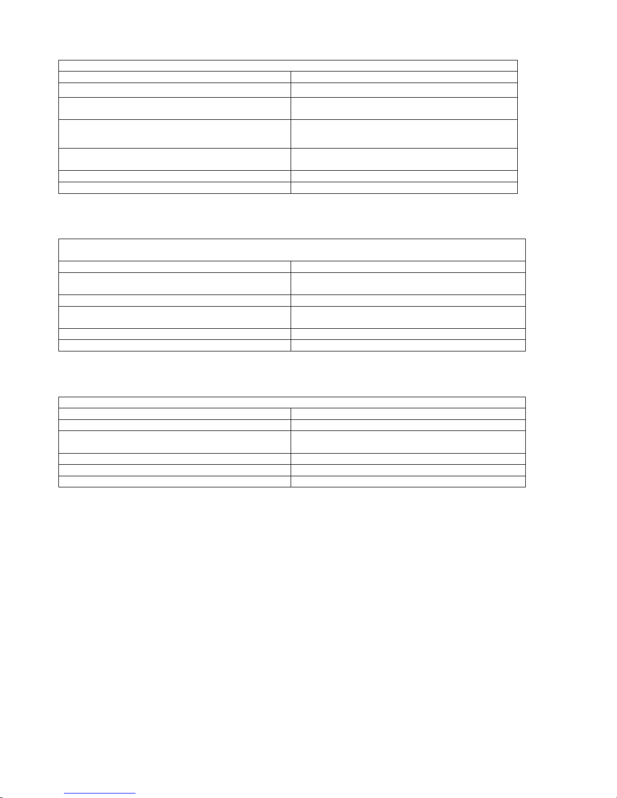
3.3 Troubleshooting
Supply air is too cold
Possible cause
Remedy
The exhaust filter is clogged.
Change the filter
The heat exchanger rotor is not rotating
Check if the belt is loose or broken, replace it if
necessary.
The motor of the heat recovery rotor does not work.
Contact service technician
The overheating protector of the after-heating coil is
out of order
switch off the alarm, if the fault reoccurs, contact
service technician
The exhaust fan doesn't work
Contact service technician
The insulation of the ducts is insufficient
Add more insulation
Ventilation intensity is weaker than usual
Possible cause
Remedy
HRV settings are not configured properly
Consult competent technician to configure settings of
your HRV
Clogged filters
Change the filters
Fan speed is too low
Choose higher fan speed or adjust the fan speed
settings through the service menu
The air intake grille is clogged
Check and clean the grille
The fan wings are dirty
Clean the fan wings
Noise level is higher than usual
Possible cause
Remedy
The filters are clogged
Change the filters
The heat exchanger is not working and the motor
shakes and roars.
Determine the cause of the problem, contact the
service if necessary
The bearings of the fan are out of order
Contact service or change the fan
The air intake grille is clogged
Check and clean the grille
The fan wings are dirty
Clean the fan wings

18
Handling of the alarms
HRV alarms are indicated in the "Alarms" menu. Active alarms are displayed in a text mode on the control
panel in the measurement / alarm-field. If several alarms are active at the same time, their codes alternate
on the display with few seconds intervals.
Five most recent alarms (codes and time) are saved in the "Alarms" menu m. Old alarms are deleted from
the HRV memory when a new alarms appear.
Alarm classes
Alarm classes are divided into three classes: A, B and C. The features and delays of alarm classes can be
seen in the alarm table below. Only A and B class alarms are stored in the memory.
An alarm can have three different states:
• Active alarms ( alarm of A or B class is switched on)
• Non-active alarms ( alarm of the A or B class have been registered and switched off, cause of failure has
been eliminated)
• Registered and switched off alarm of A class; its cause of failure has not been eliminated. After the cause
of failure is removed, HRV returns in the normal mode.
Alarm Code
Cause
Delay
A
B
C
Service note
6 months since the last service
6 months
X
Emergency stop
The emergency stop button has been pressed
0 s
X
Cold air after heat
exchanger
Temperature of the T5 Sensor is below 5 °
5 min
X
Hot exhaust air
Temperature of T3 Sensor is above 50 ° C
2s
X
Cold exhaust air
Temperature of T3 Sensor is below 14 ° C
5 min
X
Exhaust fan
malfunction
Requested speed is conflicting with exhaust fan
settings
30 s
X
Hot supply air
Temperature of T2 Sensor is above 55 ° C
2 s
X
Cold supply air
Temperature of T2 Sensor is below 10 ° C
5 min
X
Air supply fan
malfunction
Requested speed is conflicting with air supply fan
settings
30 s
X
Operation
Alarm Class A
• Supply and exhaust fans, the heat recovery rotor and the after-heating coil are switched off.
• Alarm's code is shown on the display, the alarm contact B4 is closed, lights on the control panel are on.
Alarm Class B
• Supply fan stops, the exhaust fan operates at the minimum speed, the after-heating coil is switched off.
• Alarm's code is shown on the display, the light in the control panel flashes rhythmically with two seconds
intervals.
Alarm class C
• Normal operating mode
• Alarm's code is shown on the display, the light in the control panel flashes rhythmically with5 seconds
intervals.
Acknowledgment and switching off of alarms
Alarm Class A
• Alarms can be switched off from the HRV's "Alarms" menu, the HRV does not return automatically to the
normal mode.
Alarm Class B
• Alarm can be switched off through the HRV's "Alarms" menu. When the cause of failure is eliminated, HRV
returns to the normal mode, even if the alarm has not been switched off.
Alarm class C
• Alarm can be switched off from the HRV's "Alarms" menu.

19
[Grab your reader’s attention with a
great quote from the document or use
this space to emphasize a key point. To
place this text box anywhere on the
page, just drag it.]
Condensate drain in the bottom
(1/4” internal thread)
Condensate drain in the bottom
(1/4” internal thread)
1.SUPPLY AIR
2.EXTRACT AIR
3.OUTDOOR AIR
4.EXHAUST AIR
Electric cable pass-through
Electric cable pass-through
4. Specifications

20
FAIR- 80
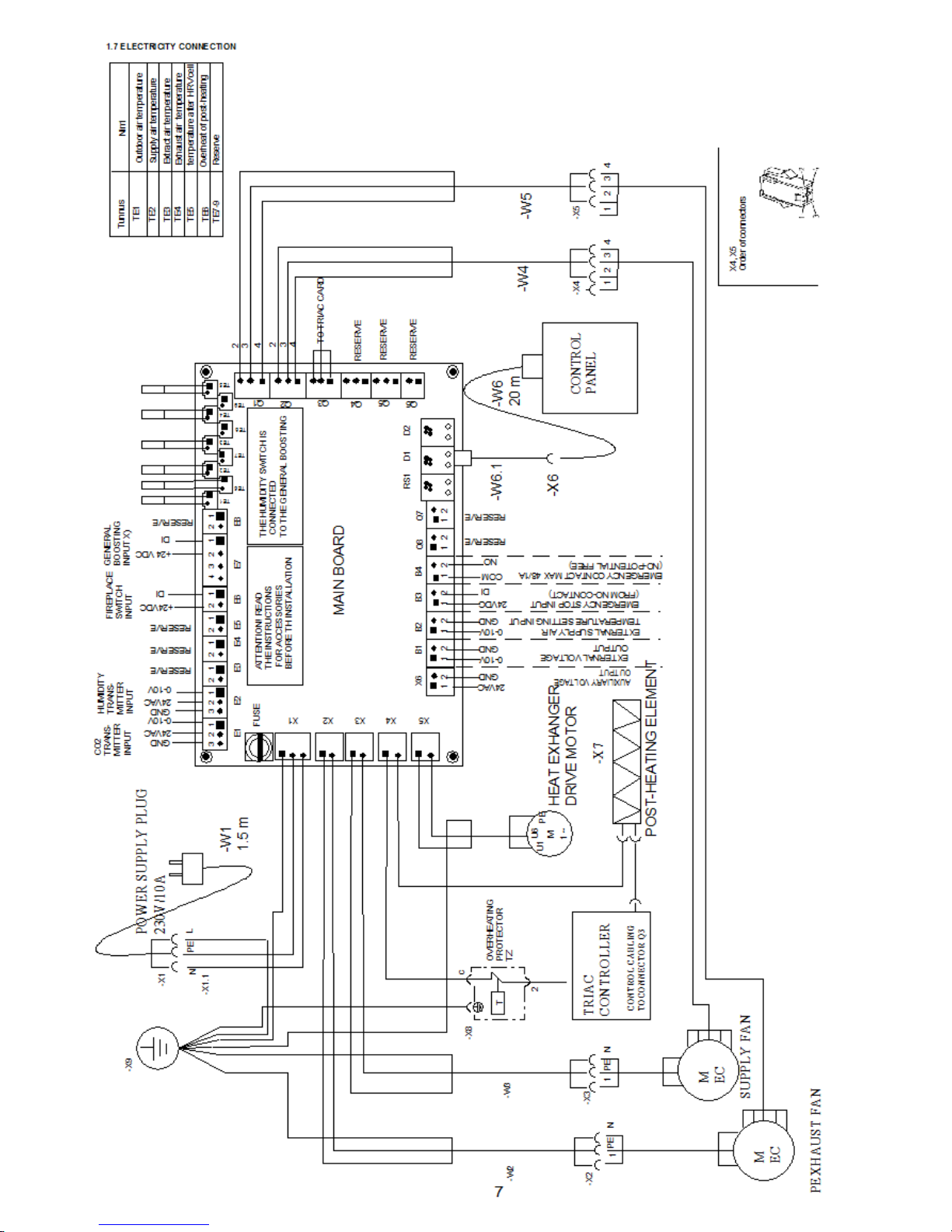
Electricity connection:
a plug, which is connected to an electricity socket (230V / 50Hz) protected by a 10 A fuse.A power cord:
length 1.5 m, built-in on the front edge of the top side the HRV.
Duct connections:
4 pcs., outer external connector ø 125 mm
Control panel:
The panel can be mounted on the wall box; connection
to HRV is with cable of 10 m, cable included.
Weight: 52 kg
Heating element:
Electronically controlled, power 800 w
Fans:
EC fans, power 119 W, 2 pcs.
Drain:
Located in the bottom of HRV, connection ¼ “, built-in hose
Maximum airflow:
90 l / s exhaust , 85 l / s supply air ( pressure loss of 50 Pa in
both streams)
5 Equipment
5.1 Standard Equipment
• Supply air filter F7
• Exhaust air Filter G4
• Post-heating element : Fair- 80 = 800 W
• Intelligent multi-function electronic user interface, control box can be mounted onto the wall, 20m cable
included
• highly efficient heat recovery wheel
• wall mounting plate with accessories
5.2 Additional equipment
• Ceiling mounting plate
• Gland plate for ducts , easy to seal the steam barrier
• CO2sensor
• Humidity sensor
• Moisture switch
• Boost switch
• External fire switch
Table of contents


