DEELAT D1047067 User manual

Digital Weighing Indicator
User Manual
WWW.DEELAT.COM

User ManualUserManual
Digital Weighing IndicatorDigital Weighing Indicator
DIGITAL WEIGHING INDICATOR
- 3 -
DIGITAL WEIGHING INDICATOR
- 2 -
Main Specication
Contents
Main Specication 3
Installation 4
Front and Back View of the Indicator 4
Key Functions 5
Connecting Load Cell to Indicator 6
Operation 7
Power On and Zero Auto 7
Zero Manually 7
Tare 7
Accumulating 7
Counting 8
User Function Setting 8
Connect Scoreboard to Indicator (Function Optional) 10
Serial Communication and Indicator Connection 10
Calibration 12
Error Indication 13
Chargeable Battery 13
Maintenance 14
Notes 15
Model Deelat Floor Scale weighing indicator
Accuracy GradeIII, n=3000
Sample Rate 10 times / second A/D conversion: Δ -∑
Load cell sensitivity 1.5~3mV / V
Scale interval 1/2/5/10/20/50 for selection
Display 6 bits LCD 6 state indicating signals
Scoreboard interface
(optional)
In serial output mode:current loop signal,
transmission distance ≤50m
Communication interface
(optional)
RS232C;
Baud rate 1200/2400/4800/9600 optional
Power supply Battery DC6V/4AH
(display Bat lo when electricity voltage below 5.4V)
Operating temperature/
humidity
0~40°C;
≤85% RH
Transporting temperature -25~55°C
Water proof IP63
DEAR CUSTOMER, PLEASE READ THE USER GUIDE CAREFULLY
BEFORE USING THE INDICATOR!

User ManualUserManual
Digital Weighing IndicatorDigital Weighing Indicator
DIGITAL WEIGHING INDICATOR
- 5 -
DIGITAL WEIGHING INDICATOR
- 4 -
Key Functions
Front and Back View of the Indicator
Installation
Keep pressing this button for 5 seconds more in weighing mode, it will
come into operator setting mode; less than 5 seconds, it will come into
counting mode.
Press this button to accumulating the weight in weighing mode. Press
this button for sample taking in counting mode.
Press this button to tare in weighing mode.
Press this button to zero in weighing mode.
Press this button to turn on/off the scale.
Press this button to stay in weighing mode or Press this button to
save/move in set mode.
FUNC
TARE
ZERO
#
*
Unit Kg Charge
A12
COUNT FUNC TARE STABLE ZERO
FUNC#
ZEROTARE
*
*
6V
Rechargable
Battery
Calibration
Span
Power
Swithc
Power
Wire
Rs 232
Interface
Load Cell
Wire

User ManualUserManual
Digital Weighing IndicatorDigital Weighing Indicator
DIGITAL WEIGHING INDICATOR
- 7 -
DIGITAL WEIGHING INDICATOR
- 6 -
Connecting Load Cell to Indicator
Power On and Zero Auto
Manual Zero
Tare
1. The 5-pin (2.54MM) socket is used to connect to the load cell, as indicated in the graph below.
Please Note: Pin 1 EX+; Pin 2 EX-; Pin 3 SHIELD; Pin 4 IN+; Pin 5: In-
2. When the 4-pin shielded cable is connected, the indicator has a long distance function.
3. The indicator must be connected to the load cell and the shield cable of the load cell
Must be grounded.
4. The sensor and indicator are static sensitive devices. Do not operate under high voltage.
Operation
1. The indicator will perform “999999-000000” to self-check when turning on. Then it will enter
weighing mode.
2. When powered on, if loading weight on the scale deviates from the zero point, but still within auto
zero setting range, the indicator will set to zero automatically; if it is out of auto zero setting
range, it is necessary to adjust the zero point or recalibrate or reset.
1. In weighing mode, when there is a degree of tolerance after removing weight, press [ZERO] to set
the indicator to zero.
2. If the displayed value deviates from the zero point, but it is still within the manual zero-range, the
[ZERO] key will return the indictor to zero. If not within the manual zero-range, then the [ZERO]
key will not function. *If this is the case, please recalibrate or reset zero parameters.
3. Only when a stable indication is displayed can the zero operation function.
1. When the indicator is in weighing mode, and the displaying positive weight is stable, pressing the
[Tare] key will deduct the displayed weight value as tare weight. The indicator will then display
net weight as “0” and the Tare indicator is on.
Accumulation
1. In weighing mode, when the displayed value is positive and stable, press the [*] key to accumulate
the present weight and display the accumulated weight. The accumulate indicator “(*)” will be
on. Press this key again and it will go back to weighing mode and the accumulate indication “(*)”
will not be displayed. The next accumulation operation must be performed after the weight
is returned to zero. When the accumulated weight is displayed, press the [Func] key to clean
the accumulated weight in Memory and press [*] to return to weighing mode. If the accumulated
weight needs to be checked, please keep the load of the platform at zero, then press [*] to display
the accumulated weight.
Connect to Load Cell
CPUA/D
CONVERSION
CN1
CN3
CN4
CN2
EX+
EX-
SHELD
IN+
IN-

User ManualUserManual
Digital Weighing IndicatorDigital Weighing Indicator
DIGITAL WEIGHING INDICATOR
- 9 -
DIGITAL WEIGHING INDICATOR
- 8 -
Counting
User Function Setting
1. In weighing mode, press [Func] to enter into the counting state. It will display “count”, and pressing the
[*] key will display “C00000”. Then press [Tare] to move the digit directed by the small triangle, and the
number corresponding with the small triangle will be increased one each time after pressing the [Zero]
key (it will enter into counting function mode after the sample quantity is input and [*] is pressed).
“0” will be displayed and the counting indication will be activated. Press [Func] key to return to
weighing mode. After entering counting mode, “count” will be displayed. Press [*] two times to enter
counting mode directly and the indicator will display the previous result. (During this process, if ERR4
is displayed, then sampling has failed, and the indicator will keep the result from the last sampling.
1. In weighing mode, hold and press [Func] for 5 seconds and it will enter user function setting
mode (mode P). There are 12 modes from P1 to P12. Press [*] to choose the mode and press [Tare]
to choose the parameter. The description of parameters is as follows:
P1 kg — Lb change
X=1: kg display
X=2: Lb display
P2 automatically power off
X=1: N/A
X=2: Power off in 10 minutes
X=3: Power off in 20 minutes
X=4: Power off in 30 minutes
P3 Baud rate setting
X=1: 9600
X=2: 4800
X=3: 2400
X=4: 1200
P4 RS232 Net/Gross weight output option
X=1: Net weight output
X=2: Gross weight output
P5 RS232 output mode option
X=1: No transmission (RS232 stop)
X=2: Continuous transmission
X=3: Continuous transmission when stable
X=4: Command mode
(Z:zero; T:tare;R:transmit weight data once time)
X=5: Current loop output
X=6: Keep for Printing
P6 Backlight setting
X=1: No backlight
X=2: Automatic backlight
X=3: Backlight On
P7 Zero-tracking range
X=1: 0.5e
X=2: 1.0e
X=3: 1.5e
X=4: 2.0e
X=5: 2.5e
X=6: 3.0e
X=7: 5.0e
P8 Manual zero range
X=1: 2%FS
X=2: 4%FS
X=3: 10%FS
X=4: 20%FS
P9 Auto zero range
X=1: 2%FS
X=2: 4%FS
X=3: 10%FS
X=4: 20%FS

User ManualUserManual
Digital Weighing IndicatorDigital Weighing Indicator
DIGITAL WEIGHING INDICATOR
- 11 -
DIGITAL WEIGHING INDICATOR
- 10 -
P10 Digital ltering intensity
X=1: high
X=2: medium
X=3: low
P11 Stable time
X=1: high
X=2: medium
X=3: low
P12 Stable scope
X=1: low
X=2: medium
X=3: high
Connect Scoreboard to Indicator (Optional)
Serial Communication and Indicator Connection
1. Current loop or RS232 signal is used for scoreboard connection, which is transmitted in serial
binary code style. The baud rate is adjustable.
• Make sure that scoreboard and signal output is connected correctly. If there is something wrong
with the connection, damage will happen to the output port of the instrument and input port of
the scoreboard.
• Only use the provided connecting cable
1. Make sure that communication interface output and computer are connected correctly. Iif there
is something wrong with the connection, damage will happen to the output port of the instrument
and the input port of computer. Data format for the RS232 output is the following: the 1st is
starting the bit, the 10th is the stop bit, and the middle are 8 data bits.
Communication mode as follows:
1. In continuous mode:
The data transmitted is weight (Gross weight or net weight)
The format of G.W.: ww000.000kg or ww000.000lb
The format of N.W: wn000.000kg or wn000.000lb
Note:The position of above decimal is decided by the decimal set on the indicator.
2. In command mode:
The indicator performs the corresponding operation according to the command transmitted
from the pc.
Command R The indicator sends weight data once in receipt of command R from pc
(the format is the same as the continuous mode)
Command T The indicator tares in receipt of command T from pc (the same as tare key).
If no command is received the indicator displays CR LF
Command Z The indicator zero in receipt of command T from Z (the same as zero key If no
command is received the indicator displays CR LF
1
2
3
4
5
B port
RS 232 C 5 pin (Male)
A port
CH2.54-8P
Orange 1
Red 2
Black 3
B 4
L 5
A 6
N 7
K 8
Orange TXD
Black GND
3 Transmit Data
2 Receive Data
5 Chassis Ground
1 Carrier Detect
4 Data Terminal Ready
6 Data Set Ready
7 Request To Send
8 Clear To Send
9 Pin Port (Female)
Computer
5 Pin Port (Male)
RXD 2
TXD 3
GND 5
Red RXD

User ManualUserManual
Digital Weighing IndicatorDigital Weighing Indicator
DIGITAL WEIGHING INDICATOR
- 13 -
DIGITAL WEIGHING INDICATOR
- 12 -
Calibration
Error Indication
Chargeable Battery
1. Connect the load cell properly and then turn on the indicator and press the [#] key during initial-
ization. It will enter into the calibration mode and calibrate as following:
STEP OPERATION DISPLAY NOTES
1Press [TARE] for selection of
division [d X]
Select optional division (1/2/5/10/20/50),
press [#] to conrm
Example: 20
2Press [TARE] for selection of
DECIMAL POINT selection [P X ]
Select optional decimal point: 0~3, press [#]
to conrm
Example: 3
3 Set the full range [FULL]
Press [TARE] for selection of the digit bit; Press
[ZERO] for selection of the digit; Press [#] to
conrm the input of the full range
4Zero point calibration: Press [#]
when the stable signal is on [nOLOAD] Conrm there is no load
5
Full range point calibration:
Press [#] when the value input
is the same as the loaded weight
and the stable signal is on
[AdLOAD]
While inputting the loaded weight,
Press [TARE] for selection of the digit bit; Press
[ZERO] for selection of the digit; when the
input value is the same as the loaded weight
and the digit bit is at the highest bit, press [#]
when the stable signal is on
6[End]
7
Press the calibration span under
the lead sealing board at the
back of the indicator
It saves the calibration parameter and returns
to the weighing status.
Attention: If you do not press the calibration
switch the parameters will not be saved
2. FAST CALIBRATION FOR ZERO POINT AND FULL RANGE POINT
Press [#] while it is initializing and it will enter into the calibration mode.
3. Fast calibration for zero point:
At any point before it displays [nOLOAD], press [FUNC] and it will keep the original division,
decimal point, full range and enter into the zero point calibration mode. Press [ZERO] when the
stable signal is on and it will display [End] and keep the original full range point calibration. Press
the calibration switch under the lead sealing board at the back of the indicator and it will save the
setting and return to the weighing status.
4. Fast calibration for full range point:
Fast calibration for full range point: At any point before it shows [AdLOAD], press [ACCU] and it will
keep the original division, decimal point, full range, zero point calibration and enter into the full range
point calibration mode. When it is nished, press the calibration switch under the lead sealing board
at the back of the indicator and it will save the setting and return to the weighing status.
EER 1 The AD value is too small when calibrated at full range point.
EER 2 The zero point is out of range when calibrated at zero point.
EER 3 The zero point is out or auto zero range upon starting
EER 4 The input sample quantity is zero when sampling in counting mode.
EER 5 The input weight is zero when full scale calibrated in calibrating mode.
EER 6 The unit weight is less than 0.25e when sampling in counting mode
bAt-lo Low power
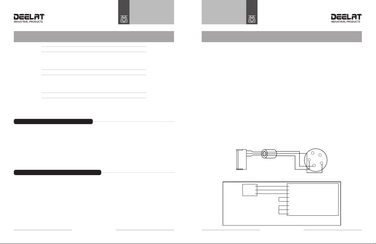
1. Turn on the AC power and the indicator will charge the battery automatically. If you don’t use the
battery frequently, you should take the battery out.
• Note: red end is +, and the black end is -. Incorrect connection will ruin the indicator.
• Note: The built-in battery should be fully charged before it is used for the rst time.
2. When you turn off the AC power, and push start key the battery will work. When [LouoL] is
displayed it means there is insufcient voltage and it needs to charge.
3. When you use the battery for the rst time, you should charge the battery for 20 hours in order
to ensure maximum battery life.
4. If you don’t use battery for a long time, you should charge the battery for 10-12 hours every
2 month period to prolong battery life.

User ManualUserManual
Digital Weighing IndicatorDigital Weighing Indicator
DIGITAL WEIGHING INDICATOR
- 15 -
DIGITAL WEIGHING INDICATOR
- 14 -
Maintenance Notes
1. To ensure proper function of the indicator, it should not be placed directly under sunshine and
should be placed in a well ventilated space.
2. The indicator should not be installed in a place with severe dust or where vibrations are present
3. The Load cell requires a solid connection with the indicator, and the system should always be
grounded. The indicator must avoid coming into contact with electric and magnetic elds.
• Avoid using the indicator in a place that has ammable gas or ammable steam:
• In order to protect the operator, indicator and relevant device, you should mount a lightning rod
in thunderstorm prone geographic areas.
• Load cell and indicator are static sensitive device, you must adopt anti static measures.
4. Do not clean the case of indicator with intensive solvents (for example: benzene and nitro oils)
5. Liquid and conductive substances should not come into contact with the indicator, otherwise the
electronic components can be damaged and the user could get shocked.
6. Make sure to cut off the power supply to the indicator and relevant devices before connecting
and disconnecting any external devices.
7. During operation, if major problems occur, operator must pull off the power supply plug immediately,
and user should return this indicator for repair. Unauthorized manufacturers, repair centers, or users
should NOT repair the scale on their own, otherwise further damage may occur.
8. In order to prolong product life, please charge the cell fully before using it. If you don’t use the
indicator for a long time, you must charge the cell every two months and for eight hours per
charging time.
9. Moving or installation must be performed carefully and avoid sudden movements, vibration,
and bumps in order to protect the storage cell from being damaged.

WWW.DEELAT.COM
Table of contents
Popular Scale manuals by other brands

Silvercrest
Silvercrest SPWD 180 H1 Operating instructions and safety instructions

Silvercrest
Silvercrest SPWD 180 E1 Operating instructions and safety instructions

Virtual Measurements & Control
Virtual Measurements & Control VB-302 instruction manual

Joycare
Joycare JC-325 instruction manual

Accurate Technology
Accurate Technology DigiScale 18 user manual

Hornady
Hornady GS-350 instruction manual