DEFA Warm Up User manual

GB
1
Wiring diagram.
_+
+-
IGNITION KEY
BLUE
BLACK
YELLO W
GREEN
RED
CONTROL UNIT
INTERIOR HEATER
PLUG FOR
INTERIOR HEATE
R
FUSE BO X
O UTSIDE TEM P.
SENSOR
BATTERY CHARGER
INTERCONNECTING LEADS
DEFA MINIPLUG
INTAKE CABLE
ENGINE HEATER
5A
RED
GREEN
YELLO W
BLACK
BLUE

GB
2
Consisting of:
Components
1 Interior heater with fitting bracket
1 Control unit
1 Battery charger/Current distributor
1 Plug for interior heater
2 Interconnecting lead 1m
1Interconnecting lead ½ m
1 DEFA Mini-plug cable 1.5 m
1 Attachment cable 2.5 m
1 12V cable rug for control unit and charger
Fastening equipment for DEFA Mini Plug
1 Fastening nut for recessing
1 Nut mounting ring for curved surfaces
1 O-ring for fastening nut
1 Fastening bracket
1 Distance sleeve for fastening bracket
2 Fastening screw for plug-in bracket 3x7 mm
2 Fastening screw for bracket M4
2 Well-nut for bracket
1
2Self-sinking screw 4.2x13 mm for 12V-
Spring Washer
Fastening equipment for other components
3 Fastening screws 3.5x16 mm for interior heater bracket
1 Fastening screw 4.2x38 mm for battery charger
4 Two-sided tape for control unit
8 Fastening strips 200 mm for interconnecting leads
1 Fuse box with fuse 6A
1 Cable 200 mm fuse box/battery

GB
3
Preparing for installation
The workshop/garage is always responsible for taking all necessary safety precautions
when installing DEFA WarmUp. Avoid locating units too close to engine components
with high temperature, for instance exhaust manifold, exhaust pipe, turbo etc. Ensure
proper distance from moving parts such as alternator, cooling fan, steering rods etc.
Use the following method to install DEFA Warm Up
1. Disconnect the minus terminal of the battery. Check the manufacturers instructions
before disconnecting.
2. Choose engine heater according to DEFAs vehicle list. Refill the cooling system with
approved engine coolant and bleed the cooling system in accordance with the
manufacturers instructions.
3. Find a suitable place for passing through the cables and mount the socket for the
interior heater in the passenger compartment.
4. Mount the interior heater in the passenger compartment and connect the Plug-In
cable from the engine compartment.
5. Fit the DEFA Mini-Plug in an accessible position in the front of the car in accordan
ce with the customers requirements.
6. Place the battery charger/relay box in correct position relative to the Plug-In cable
from the interior heater, the engine heater and the power intake.
7. Mount the control unit and connect the battery charger.
8. Connect the minus terminal of the battery.
9. Check that the DEFA Warm Up functions properly.

GB
4
Passing through the interconnecting cable to the interior.
Pass the interconnecting cable through existing holes in the inner fender or via the A-pil-
lar into the interior of the car. The plastic inner fender must be removed. Remember to
pass through the 5-lead cable for the control unit.
Be careful if it is necessary to drill a hole to pass through the DEFA
Plug-In cable from the engine compartment to the interior. Do not
drill in double plating or reinforcements.
The DEFA Ø20mm hole saw is a particularly suitable tool for this
task. Make sure that the tool does not damage fitted components,
brake lines, electrical cables etc. For the rust-proofing warranty to
be valid, scratches and cuts in the paint must be repaired with a ma-
terial approved by the vehicles manufacturer.
Use the enclosed rubber bushing to seal the hole. Make sure the
rubber bushing is fitted properly as it may otherwise be a conduit
for water seepage into the passenger compartment. DEFA Plug-In
cables should slope downwards from the passing through point in-
to the engine compartment (1) so that water or humidity does not
run along the cable into the car interior (2).
When drilling a hole in the engine compartment wall, care must be taken so
the tool does not damage fitted components, brake lines, electrical cables etc.
Installation of the interior heater.
Install the interior heater and its plug in a suitable location in the passenger compartment.
Use the enclosed mounting bracket to mount the heater.
The interior heater can be installed in the following positions:
Upside-down, e.g. under the glove compartment; on the side wall, e.g. on the middle con-
sole or the A-pillar. The airflow must not be directed downwards. The interior heater
must be mounted so as to satisfy the requirements for free space around the heater. The
requirements are shown in the sketches below.
Mounting with the bracket.
m in 30cm
m in 10cm
m in 10cm
m in 10cm
12
12
m in 30cm
m in 10cm
m in 10c
m

GB
5
1
2
1.5 cm
The mounting bracket is designed for use on uneven
surfaces. Remove the bracket from the heater by
pushing it backwards. The bracket is mounted by
means of the enclosed distance sleeves (1) shown in
the picture to the right. All the holes in the bracket
can be used, but it is desirable for the mounting
points to be as far apart as possible. Use the enclos-
ed 3 screws to fasten the mounting bracket. The dis-
tance sleeves must be removed before the bracket is
mounted. Guide the interior heater onto the bracket
and push (2) until a click is heard.
The interior heater must be positioned so that it does not constitute a safety
hazard in case of a collision or hard braking.
When used in a vehicle the interior heater must always be connected to a power socket
mounted in the interior and connected to a power outlet on the outside with intercon-
necting lead or mini-plug. Only original DEFA connector kits with original
DEFA Mini-Plug may be used. The lead may only be connected to an earthed power
socket.
Make sure that screws or drill bits do not damage cables or control units on
the back of the panel where the mounting bracket and the plug is fitted.
Installation of the DEFA Mini-Plug and interconnecting cables
Fitting of DEFA Mini-Plug.
Recessing the Mini-Plug.
The DEFA Mini Plug should be mounted in such a way that it is
protected against splash and mechanical damage and so that the con-
nector lead can be connected without difficulty. When the mounting
surface for the fastening nut is uneven the enclosed mounting ring
should be used. Insert the O-ring is in the groove in the plastic nut
or on the mounting ring if this is used. Drill a hole with a diameter
of Ø24,5 mm and file a guide groove with a diameter of Ø3 mm to
recess the Mini plug. (Special tool no. 460840). Make sure there is sufficient space in the
rear for the cable and enough room for the fastening nut. Be careful when drilling so that
mounted components, cables etc. are not damaged. The plug can be painted, if desirable,
in the cars own colour.

GB
6
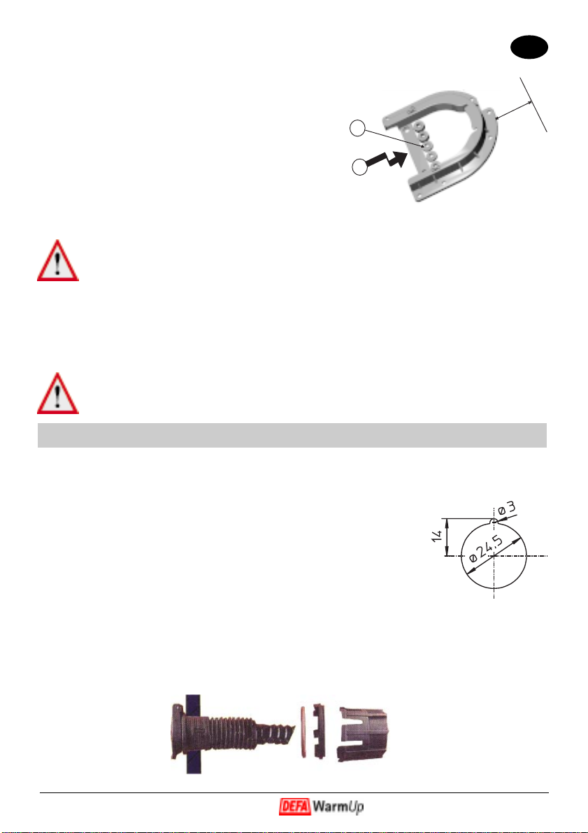
The bracket can be mounted both ways depending on the
mounting location. The plug can be adjusted and turned to
the required position. Normally the plug is fitted with the
cover hinge pointing upwards, but may also be fitted with
the hinge to one side. The plug must not be fitted with the
cover hinge pointing downwards.
Drainage.
Regardless of whether the DEFA Mini Plug is mounted
recessed or on the bracket, the plug should be fitted so
that it leans downwards towards the cover allowing wa-
ter and condensation to be drained away. If the plug is
fitted leaning upwards, the lower of the three weakened
points(1) on the plug MUST be removed for drainage.
It is best done with a knife or similar tool. (Do not push
the plastic piece into the plug).
Earth connection.
The earth connection (black single-core cable with ring-
shaped cable shoe) MUST be connected to a good earth
point on the metal part of the car body. Paint, underse-
al etc. MUST be removed from the contact point of the
earth connection. A toothed washer must be used both
under the screw head and between the cable shoe and the
car body.
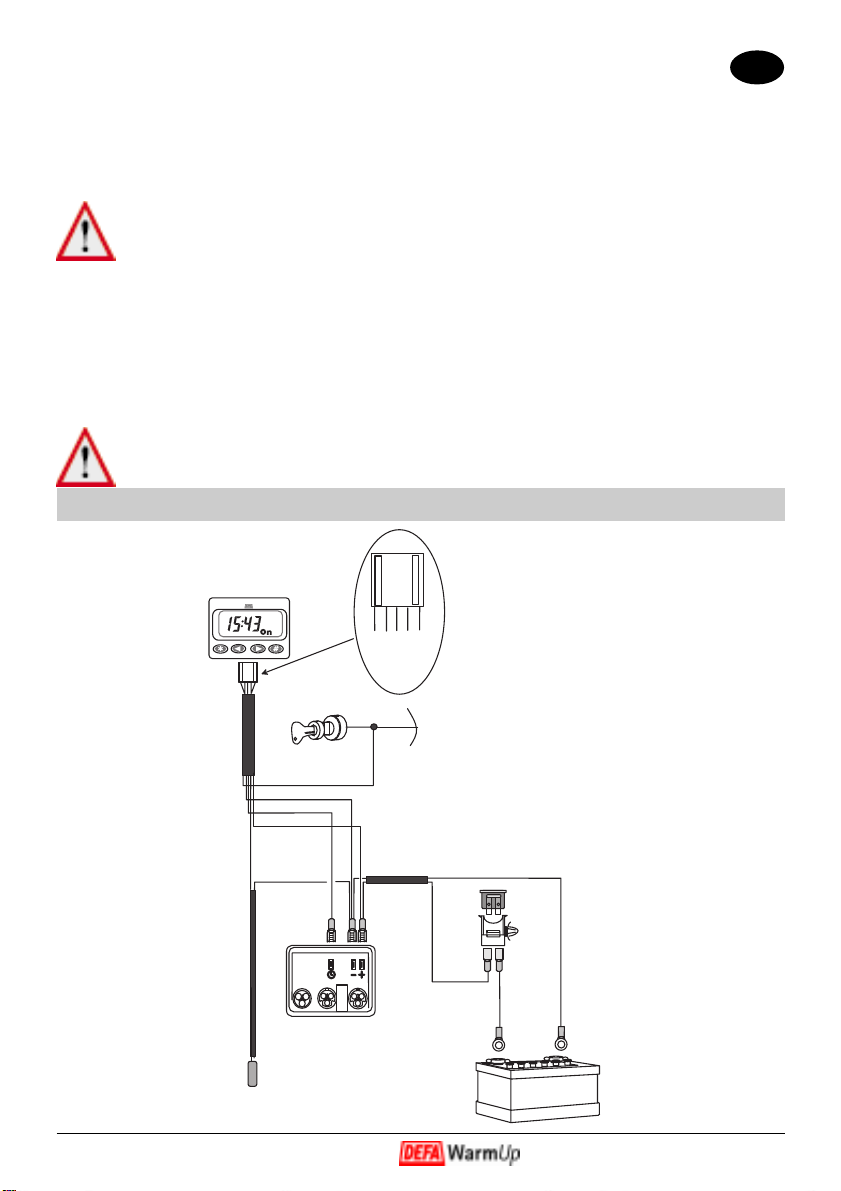
DEFA Plug-In connectors and interconnection leads.
It is important when connecting the leads to press the contacts together sufficiently hard
for the O-ring on the male contact to seal properly. Make sure the O-ring is not pushed
out of the groove when pressing the contacts together. Fasten the extension leads with
plastic strips in suitable spots in the engine compartment, well away from sharp, hot or
moving parts. Battery charger.
Connect the battery charger in accordance with the wiring diagram on the cover. Con-
nection to the battery must always be made with the enclosed fuse. Use the fastening hole
at the bottom of the charger and mount the charger with a body screw or plastic
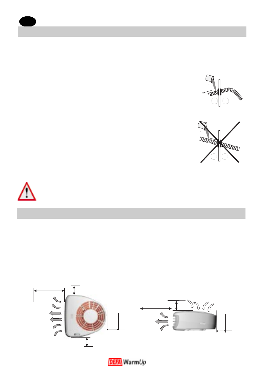
strips.Route the cables straight away from the contacts (1)
on the battery charger so that the Plug-In contacts are not
bent or twisted (2). Make sure the battery charger is not
placed too close to hot parts such as exhaust
The cable for the control unit is connected to the contact
under the small cover. The cover is opened as shown in the
picture. The plug is fitted so that the red cable is located
as shown in the picture (1). The thick part of the cable must
be inside the edge (2) of the cover so that the tension when
closed keeps the cable in place.
12
1

GB
7
_+
+-
IGNITON SW ITCH
BLUE
BLACK
YELLO W
GREEN
RED
CONTROL UNIT
FUSE
O UTSIDE TEM P.
SENSOR
BATTERY CHARGER
5A
RED
GREEN
YELLO W
BLACK
BLUE
Find a suitable position for the control unit in the passenger compartment. Dashboard,
switch panel, console or sun visor are good possibilities. Clean the surfaces carefully with
a suitable grease solvent (for instance Acrysol). Do not use acetone, trichlorethylene, Bre-
akclean or similar products as PVC and plastic may be damaged. Fasten the control unit
by means of the enclosed double-sided tape.
Note that the two ends of the cover are different. It can only be opened from
one.
It must also be positioned well clear of moving parts such as pulleys, cooling fan and stee-
ring rods. Two or more battery chargers can not be connected in series or parallel to charge
e.g. a 24V device, or to achieve higher voltage. Avoid charging batteries in an enclosed
area, as there is a potential danger of explosion. The temperature of the battery may not
exceed +40ºC during charging. The charger contains high voltage current. Therefore
do not use a drill on it or open it.
The charger must be positioned with the contacts facing DOWN and is fas-
tened by means of screws or strips.
Control unit.

GB
8
The cable for the control unit is connected to the
contact under the small cover. The cover is ope-
ned as shown in the picture. The plug is fitted so
that the red cable is located as shown in the pic-
ture (1). The thick part of the cable must be insi-
de the edge (2) of the cover so that the tension
when closed keeps the cable in place.
Find a suitable position for the control unit in the
passenger compartment. Dashboard, switch pa-
nel, console or sun visor are good possibilities.
Clean the surfaces carefully with a suitable grease
solvent (for instance Acrysol). Do not use aceto-
ne, trichlorethylene, Breakclean or similar pro-
ducts as PVC and plastic may be damaged. Fas-
ten the control unit by means of the enclosed do-
uble-sided tape.
Note that the two ends of the cover are
different. It can only be opened from
one end.
Fit the outside temperature sensor in the front of
the car, and place it so that hot parts do not influence it.
Claims
Claims may not be made for damage resulting from:
· Normal wear and tear.
· Faulty installation.
· Lack of maintenance and faulty or irresponsible use.
· The use of non-original connectors/leads or use together with non-original parts.
· Modification or repairs of the product, or attempts thereon, carried out by others
than DEFA without written authorization by DEFA to carry out such modificati
on or repair.
· Conditions after delivery beyond the control of DEFA.
SEND CLAIMS TO:
DEFA A.S
Service Department
N-3540 NESBYEN
Telephone: 32 06 77 20
Fax: 32 06 77 01
e-mail: [email protected]
Remember to enclose a copy of receipt/invoice!
RØD
2
3
RED
Other DEFA Remote Starter manuals
Popular Remote Starter manuals by other brands

Audiovox
Audiovox Prestige APS-57a owner's manual

Chamberlain
Chamberlain 747E Series manual

Genie
Genie KEP-1 Installation and operating instructions

Schumacher
Schumacher SJ1342 owner's manual

Bulldog Security
Bulldog Security Deluxe 62I Installation and owner's guide

Mazda
Mazda GENUINE C930 V7 620 User instructions