deffner & Johann HAROLUX 5510 500 User manual
INSTALLATION AND OPERATING INSTRUCTIONS
Die in diesem Produktdatenblatt genannten Spezifikationen dienen nur zur Produktbeschreibung und beziehen sich
auf den Zeitpunkt unmittelbar nach der Produktion bzw. Import des Produktes. Sie entsprechen den Angaben des
Herstellers. Eine rechtsverbindliche Zusicherung bestimmter Eigenschaften oder der Eignung für einen bestimmten
Einsatzzweck kann hieraus nicht abgeleitet werden. Durch unsachgemäßen Transport und / oder unsachgemäße
Lagerung können sich Änderungen ergeben. Die Angaben in diesem Produktdatenblatt entbinden den Verarbeiter
nicht von eigener Prüfung der Eigenschaften des Produktes und dessen Eignung für die vorgesehene Verwendung.
Supplies for RESTORATION | CONSERVATION | ART HANDLING – SINCE 1880
5510 500 | HAROLUX
Version 05/2021 D&J Subject to change without notice.
INSTALLATION AND OPERATING INSTRUCTIONS HAROLUX LED
Please observe the following oints during installation and initial setu :
Initial setup of the wor place lamp
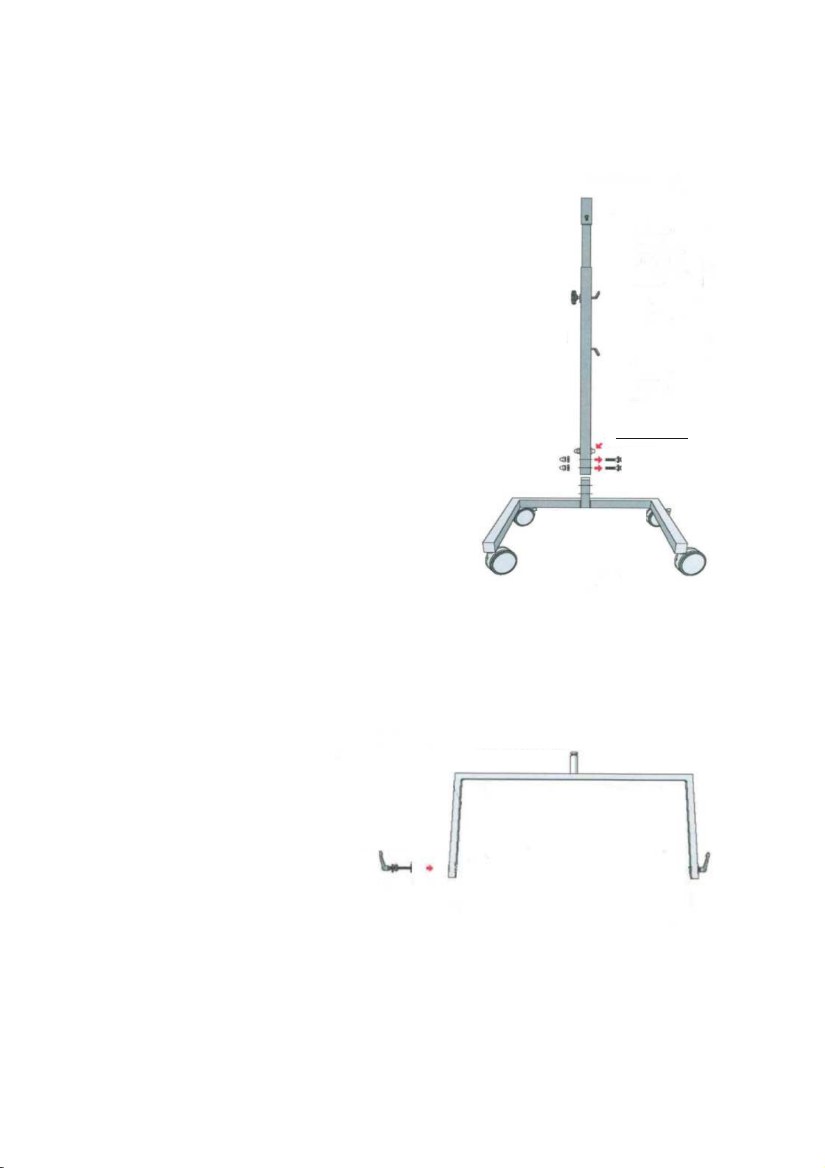
Figure 1
Handle screw for
gas pressure spring
Please only loosen
after complete
assembly of the
lamp body
Do not loosen
Loosen with
Allen key
Make sure brakes
are locked before
installation
Figure 2
Connect the
screw-clam
holder to the
lam using a
U-bracket
Mounting the stand
1) Place the stand column on the pivot of
the base frame and secure it with the two
screws provided. Tighten these firmly.
Please note: The thread on the upper part of
the stand column must point forward
towards the base frame.
DO NOT loosen the grip screw on the side
of the stand column, otherwise the gas
pressure spring will extend the stand
column. DO NOT loosen the pre-assembled
screw (red screw head). It fixes the gas
pressure spring in the stand column.
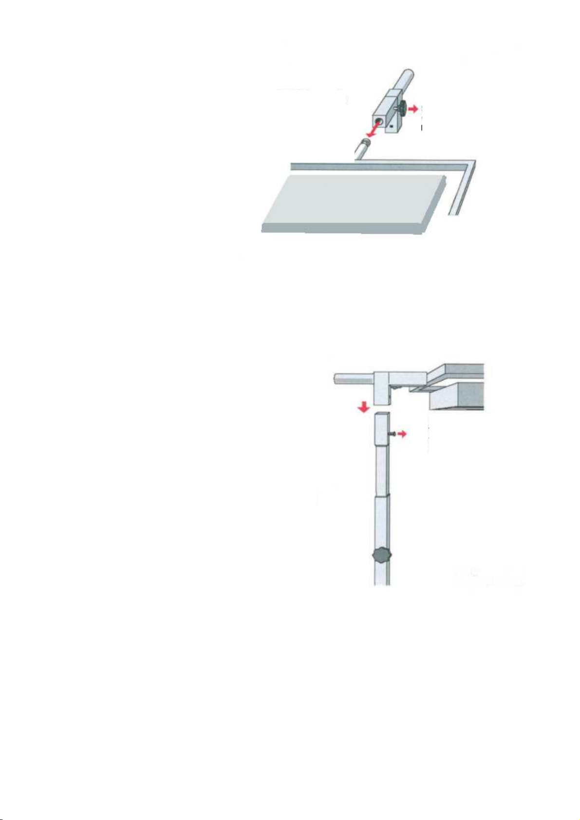
2) Connect the U-bracket to
the lamp body on both sides.
Use the clamping screws with
the washers supplied. Use a
soft washer between bracket
and housing. Use the second
soft washer and the hard
plastic washer between the U-
bracket and the clamping
screw.
Version 05/2021 D&J Subject to change without notice.
3) O en the ositioning screw
and insert the ivot com letely
into the socket of the stand
column head.
Note: Before
doing so, engage the locking
brakes on the base frame
castors. If necessary, it may be
hel ful for a second erson to
hold the stand during assembly
while the U-bracket ivot is
ushed into the socket of the
stand column head.
Tighten the ositioning screw.
4) Place the stand column head on the stand
column and tighten it with the screws
su lied.
Operating the lamp
•Permissible voltage range: 220-240V/50-60 Hz AC.
•Insert the mains cable su lied into the socket on the rear of the housing, then connect the
mains lug to the ower outlet. .
•The lam is only intended for use in dry indoor areas ( rotection class IP20). Maximum
ermissible ambient tem erature ta = 25°. Exceeding this limit will reduce the service life.
•The HAROLUX LED is equi ed with dimmable electronic converters. The workstation lam can
be dimmed from 1-100% using the multifunction ush-button in the lam (see TouchDIM).
Figure 3
Attention:
It is im erative to grease
the ivots! Otherwise there
is a risk of tilting.
Loosen
‘ ositioning screw’
before inserting.
Figure 4
Insert the
lam body
without tilting,
referably with the hel of
a second erson!

TouchDIM function: Switching on and off, dimming, synchronisation
•The lam can be switched and dimmed using the multifunction ush-button in the lam housing.
•Pressing the button briefly (< 0.5 sec.) switches the light on or off.
•Pressing and holding the button (> 0.5 sec.) dims the light u /down (the dimming direction
changes each time the button is ressed)
The dimming converter has two o erating modes to choose from:
MODE 1: The switch-on value is always the last dimming value before the lam was last
switched off (or, for exam le, after a ower failure). This is the factory default
setting.
MODE 2: The switch-on value is the value set by double-clicking the button (when the lam is
switched on)
stored value (press twice, within 0.4 sec., successful storage process is
acknowledged by the LEDs flashing twice).
This reference value can be manually overridden at any time by ressing and holding
the button.
Delete the reference value by double-clicking the button with the lam switched off,
thereby returning to MODE 1.
NOTE: For technical reasons, the LEDs may be asynchronous in o eration, as the two LED drivers in
the luminaire are dimmed by a central button, i.e. that the two drivers and thus the 4 connected LED
modules no longer behave the same.
In this case, the system can be synchronized again by the following 4 ste s:
1. Press the button long (> 0.5 seconds) - all LEDs are switched on.
2. Press the button briefly (< 0.5 seconds) - all LEDs switch off.
3. Press the button long (> 0.5 seconds) - all LEDs are switched on and dim until desired light level is
reached (all modules or drivers are synchronous again).
4. Double-click (o tional) - if necessary save dimming as a reference value (see mode MODE 2).
Due to roduction-related tolerances of the electrical or o tical arameters of electronic com onents, a different color and
brightness im ression of LEDs can be created, es ecially at low dimming level. This does not constitute a roduct fault. By
mixing the emitted light, an uniform and colour-consistent illumination is nevertheless ensured on the lighted surface.
Operating the stand
•The lam body is secured in the U-bracket by means of clam ing screws and lastic washers.
Tighten the clam ing screws just enough so that a slight resistance is felt when moving the lam s
and the lam remains in the selected osition.
•To turn the lam , loosen the adjusting screw on the side of the stand column head.
•To adjust the height, hold the lam with one hand by the handle (tube) located on the back of
the stand column head and slowly turn the handle screw on the side of the stand column. The
stand column moves u wards by means of a gas ressure s ring. When the desired height is
reached, retighten the gri screw and only then release the tube at the back of the stand column
head.
•Secure the osition of the stand with the locking brakes on the base frame castors.
SAFETY INSTRUCTIONS
Harolux LED is a daylight lamp for professional use in restoration studios. It may only be operated
by users who have read and understood these operating instructions. The lamp is not intended for
any other application. Li ewise, the lamp must not be used outdoors or in damp or dusty wor ing
environments.
Version 05/2021 D&J Subject to change without notice.

Version 05/2021 D&J Subject to change without notice.
Ensure that the stand and the lamp body do not collide with any pieces of art when adjusting the
height of the Harolux or moving it around the room.
For safety reasons, the lamp must not be operated “open” (i.e. without a glass cover). Defective
glass covers must be replaced immediately.
Cleaning: Use a slightly moistened microfibre cloth / Evolon CR. Do not use abrasive or scratching
cleaning media.
Protect the device from high voltage pea s from the mains – such as those caused by inductive
loads. Operate such loads on a different mains phase. Overvoltage inevitably results in the
destruction of the converters.
•
The lam is maintenance-free and does not need to be o ened by the user
•Never work on the lam when it is connected to the mains
•The bulbs of this lam must not be re laced or substituted by the user. CAUTION –
Danger of electric shoc !
•In case of malfunctions or failure of LED modules, contact Deffner & Johann
Product description
•Sheet steel housing, owder-coated
•Two integrated mounting M8 threads for mounting the lam on the Harolux floor stand using clam ing
screws.
•Mains connection through IEC 60320-1 lug via flexible connecting cable H05VV-F 3G1 mm² with earthed
lug 10/16 A 250 V, suitable for German and French earthing system (other country-s ecific lugs on
request)
•8 daylight-white latest generation LED modules
Technical specifications
LED ower a rox. 128W
Power consum tion a rox. 132W (0.57A @ 230V)
Source of light: LED
modules
a rox. 19,200 lm
Colour of light daylight-white 5700 K
Colour rendering (CRI) > 90 (ty ically 93)
Anti-glare rotection through innovative micro rismatic disc combined with wafer-thin high-tech
diffuser foil
Mains su ly 220 – 240 V/50-60 Hz
Protection ty e IP 20
Protection class I
Button
(ON/OFF/DIM/MODE)
integrated into the housing
Dimming range 100 – 1%
Included:
- 1 x stand
- 1 x lamp body
- 1 x supply cable
- 2 x castors with loc ing bra e, 2 castors without loc ing bra e
- 2 x clamping unit
Please eep this manual readily to hand after installation!
Table of contents


