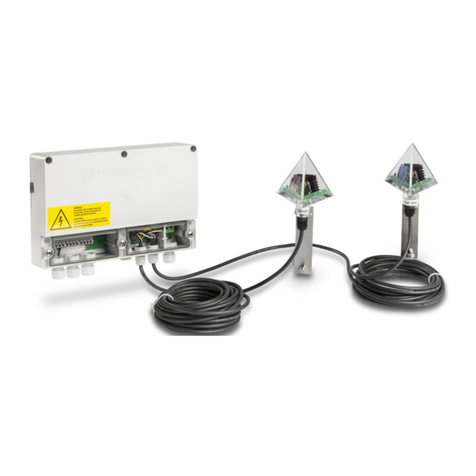
Deger MLD Control Energy Converter S1 User manual

A
M
E
n
A
SSE
M
LD
n
ergy
S1
0
MBL
Y
C
o
Con
v
0
0-PF
Y
IN
S
o
ntr
o
v
erter
-SR
S
TRU
C
o
l
S1
C
TION

18.04.2018 ASSEMBLY INSTRUCTIONS MLD CONTROL EK-S1 Page 2
Copyright
All information presented in this technical document and the drawings and technical descriptions made
available by DEGER remain the property of DEGER and may not be reproduced without prior explicit written
permission from DEGER.
We reserve the right to make technical changes.
Version: 2018-03-01

18.04.2018 ASSEMBLY INSTRUCTIONS MLD CONTROL EK-S1 Page 3
List of contents
Abbreviations ................................................................................................................................................. 5
1.1Introduction ........................................................................................................................................ 6
1.2Basic safety information ..................................................................................................................... 6
1.3Exclusion of liability ............................................................................................................................ 6
1.4For your safety ................................................................................................................................... 6
1.4.1Intended purpose of the DEGERtracker ........................................................................................ 6
1.4.2Personal protective equipment ...................................................................................................... 6
1.5Symbols used .................................................................................................................................... 7
1.6Presentation of information ................................................................................................................ 7
1.6.1Lists and instructions ..................................................................................................................... 7
1.6.2Safety information .......................................................................................................................... 7
2Energy Converter S1 (EK-S1) .................................................................................................................... 8
2.1EK-S1: Function ................................................................................................................................. 8
2.2EK-S1: Cable connections ................................................................................................................. 8
2.3EK-S1: Pin assignments .................................................................................................................... 9
2.4EK-S1 LED – display ...................................................................................................................... 10
2.4.1LED’s indicating main functions: .................................................................................................. 10
2.4.2LED assignments ......................................................................................................................... 11
3Manual Control ......................................................................................................................................... 12
3.1Joystick Functions ........................................................................................................................... 12
3.1.1Pin assignment ............................................................................................................................ 12
4Wind Guard .............................................................................................................................................. 13
4.1Wind guard....................................................................................................................................... 13
4.2Assembly ......................................................................................................................................... 13
4.3Connection ....................................................................................................................................... 13
5Snow Sensor ............................................................................................................................................ 14
5.1Function ........................................................................................................................................... 14
5.2Positioning ....................................................................................................................................... 14
5.3Assembly ......................................................................................................................................... 15
5.4Connection ....................................................................................................................................... 15
6Connections .............................................................................................................................................. 16
6.1Block diagram .................................................................................................................................. 16
6.2CAN-Bus .......................................................................................................................................... 17
6.2.1CAN-Bus connections EK-S1 ...................................................................................................... 17
6.2.2Connecting CAN-Bus to the management PC ............................................................................ 17
6.3Uninterruptible power supply for a DEGERtracker .......................................................................... 18
7Start-up ..................................................................................................................................................... 19
8Clearance Check ...................................................................................................................................... 19
8.1Start of check ................................................................................................................................... 19
8.2Scope ............................................................................................................................................... 19
9Technical Data .......................................................................................................................................... 20
9.1Electrical ratings .............................................................................................................................. 20
9.2Electrical norms ............................................................................................................................... 20

18.04.2018 ASSEMBLY INSTRUCTIONS MLD CONTROL EK-S1 Page 4
9.3Climatic conditions ........................................................................................................................... 20
9.4General ............................................................................................................................................ 20
10Troubleshooting ................................................................................................................................... 21
10.1Troubleshooting diagram for Energy Converter EK-S1 ................................................................... 21
10.2Fault report....................................................................................................................................... 22
11Maintenance ........................................................................................................................................ 23
12Cleaning ............................................................................................................................................... 23
13Decommissioning ................................................................................................................................ 23
13.1Disassembly .................................................................................................................................... 23
13.2Disposal ........................................................................................................................................... 23
14Conformity Declaration ........................................................................................................................ 24
15Publisher Information ........................................................................................................................... 25

18.04.2018 ASSEMBLY INSTRUCTIONS MLD CONTROL EK-S1 Page 5
Abbreviations
EL = Elevation(east-west orientation)
CTC = Central Tracker Control (software)
EK-S1 = Energy Converter S1
MLD = Maximum Light Detection
MLD Control = Energy Converter, MLD sensor, wind sensor, snow sensor
PPE = Personal Protective Equipment
UPS = Uninterruptible power supply

18.04.2018 ASSEMBLY INSTRUCTIONS MLD CONTROL EK-S1 Page 6
These assembly instructions were created for the DEGERtracker. They are a component of the product and
must be saved for the entire lifespan of the DEGERtracker. The assembly instructions must be included with
the DEGERtracker should it be transferred to another party.
Read these assembly instructions in their entirety before starting assembly work and keep them available
at all times during the assembly process.
Only qualified personnel may perform assembly work.
Keep all objects out of the theDEGERtracker’sfull range of pivoting motion throughout its full range of
motion.
Take necessary actions to protect the installed DEGERtracker in its full range of motion from unauthorized
access, such as enclosing it within a fence. Near the entry area to the DEGERtracker there must be a
warning sign stating that it is prohibited to remain within the range of pivoting motion.
Lightning protection and grounding must be installed in all photovoltaic systems according to country-
specific guidelines as stipulated in DIN VDE 0185 and 0100.
Do not operate the DEGERtracker if the wind guard is not functioning. Always keep the module surface in
the SAFE position (table position) until the wind guard has been tested for function.
If snow has accumulated on the module surface, the module surface must first be cleared. This is
accomplished by manually controlling via the CTC software, the joy stick or through the snow sensor. If no
functioning CTC remote access, joy stick and/or snow sensor is available, the module surface must be
cleared manually. The snow sensor shall not release the module surface from the obligation to be cleared
of snow.
DEGER recommends an Uninterruptible Power Supply (UPS) to ensure the function of the wind monitor.
As a rule, DEGER’s General Terms and Conditions shall apply. The contents of these documents are
checked continuously and modified as needed. The assembly instructions are available for download in the
dealer section on the website, www.DEGER.biz, and they can also be obtained through the traditional
distribution channels.
Warranty and liability claims will be void if any type of damage occurs that results from one or more of the
following causes:
- Improper or unauthorized use of DEGERtracker
- Operation of DEGERtracker in an improper environment
- Operation of DEGERtracker without taking into account the statutory safety regulations applicable at the
place of installation
- Non-observance of warnings and safety information in all documents relevant to the product
- Operation of DEGERtracker in the absence of proper safety and protective measures
- UnauthorizedmodificationstoDEGERtracker
- Drilling holes in any housing, e.g. EK-S1. Use existing free holes for mounting the housings.
- Failure of the DEGERtracker due to the influence of connected or neighbouring devices outside of the the
permitted limits
- Catastrophesandforcemajeure
1.4.1 Intended purpose of theDEGERtracker
The MLD control with EK-S1 is intended only for the purpose of controlling DEGERtrackers.
DEGERtrackers can be used in the private and commercial sector. They are designed for outdoor installation
and for building integration.
1.4.2 Personal protectiveequipment
The client must provide enough safety equipment for assembly and maintenance work. Supervisors must
ensure safety equipment is worn.
The following safety equipment is mandatory:
- Protectivehelmet
- Safetyshoes
- Safetygloves
Fall protection equipment and PPE to prevent falling when working more than 1 m above the ground

18.04.2018
The followi
n
1.6.1 Li
s
Lists
Lists haveb
- List
- List
Instructio
n
Instructions
1. Step 1
2. Step 2
Instructio
n
Instructions
Instructio
n
Instructio
n
Results
Results of
a
>>Result
1.6.2 Sa
f
The followi
n
_________
_
D
A
I
m
_________
_
W
P
o
_________
_
C
A
D
a
_________
_
N
O
F
a
_________
_
n
g symbols
a
No una
u
Read a
n
s
ts andins
t
ulletpoints:
n
s in a certa
s
that must b
e
n
s without a
s
that do not
n
n
a
n action ar
e
f
etyinfor
m
n
g safety inf
o
_
________
_
A
NGER!
m
minent dan
g
_
________
_
W
ARNING!
o
ssible dan
g
_
________
_
A
UTION!
a
nger with l
o
_
________
_
O
TE!
a
ilure to obs
e
_
________
_
a
ppear on th
e
u
thorized ac
c
n
d follow th
e
t
ructions
inorde
r
e
followed i
n
certain ord
have to be f
o
e
indicated b
y
m
ation
o
rmation is u
_
_________
_
g
er with a hi
g
_
_________
_
g
er with a m
o
_
_________
_
o
w risk; failu
r
_
_________
_
e
rve this inf
o
_
_________
_
ASSEMBLY IN
e
DEGERtr
a
c
ess
e
operating
m
a certain or
d
e
r
o
llowed in a
c
y
a double a
r
sed in this d
_
_________
_
g
h risk; failu
r
_
_________
_
o
derate risk;
f
_
_________
_
r
e to observ
e
_
_________
_
o
rmation ent
a
_
_________
_
N
STRUCTIONS
a
cker and ar
e
m
anuals and
r
der are num
certain orde
r
r
row:
ocument:
_
________
_
r
e to observ
e
_
________
_
failure to ob
s
_
________
_
e
can lead t
o
_
________
_
a
ils the risk
o
_
________
_
MLD CONTR
O
e
used in th
e
safety infor
m
bered:
r
are listed
w
_
_________
_
e
will lead to
_
_________
_
s
erve can le
a
_
_________
_
moderate p
_
_________
_
o
f property d
a
_
_________
_
O
L EK-S1
present do
c
m
ation befor
e
w
ith bullet po
i
_
_________
_
severe phy
s
_
_________
_
a
d to severe
_
_________
_
hysical injur
y
_
_________
_
a
mage.
_
_________
_
c
ument:
e
start-up
ints:
_
________
_
s
ical injury o
r
_
________
_
physical inj
u
_
________
_
y
.
_
________
_
_
________
_
Page
7
_
_________
r
death.
_
_________
u
ry or death.
_
_________
_
_________
_
________
7

Mot
o
Mas
t
Mot
o
Slav
e
In
c
M
a
18.04.2018
2 Ene
Applies in
Reverse di
This functio
The motor
w
than 4 hour
2.2 EK-
S
The EK-S1
for the CA
N
The PG gla
installation
a
PG glands
f
No
t
A
ll
P
ho
u
o
r 1
t
er
o
r 2
e
c
linationsen
s
a
ster
Theft
p
(opti
o
rgy Co
n
general:
rection fun
c
o
n ensures t
h
w
ill switch o
n
s. The exter
n
S
1: Cable
c
is delivered
N
-Bus (M20)
nds for the
w
a
nd are incl
u
f
or the UPS
a
t
e!
P
G glands
m
u
sing to avoi
d
In
c
Sl
a
s
or
p
rotection
o
n)
n
verte
r
S
1. External
i
2. External
i
c
tion:
h
e module s
u
n
for 12 min
u
n
al inputs, j
o
c
onnectio
n
with prewire
and AC po
w
w
ind guard (
M
u
ded as an
a
a
nd theft pr
o
m
ust fit with t
h
d
moisture i
n
c
linationsen
s
a
ve
UPS
(optio
n
ASSEMBLY IN
S
1 (EK-
S
nput has pri
o
nput from w
i
u
rface is faci
n
u
tes once th
e
o
ystick, MLD
n
s
d MLD-sens
w
er (M16) wil
l
M
20) and th
e
a
ccessory.
o
tection (bot
h
h
e installed
c
n
side. Under
g
s
or M
L
W
(a
n
)
N
STRUCTIONS
S
1)
o
rity over M
L
ind sensor h
ng east the
n
e
EK-S1 has
sensor and
s
or, Inclinati
o
l
be pre-inst
a
e
snow sens
o
h
M16) can
b
c
ables from
c
g
round slav
e
L
D sensor
W
ind guard
nemometer)
MLD CONTR
O
L
D sensor.
as priority o
v
n
ext mornin
g
not register
e
wind monito
o
n sensor ca
b
a
lled.
o
r (M16) are
b
e provided
o
c
ustomer si
d
e
cables mu
s
CAN
B
In
Snow s
e
O
L EK-S1
v
er external
m
g
to receive t
h
e
d a signal a
r have priori
t
b
ling and m
o
only neede
d
o
n request.
d
e and must
s
t be laid in
a
B
us
e
nsor R
e
(
o
C
A
O
manual con
t
he first rays
a
t terminal X
F
t
y.
o
tor cabling.
d
one time i
n
hermeticall
y
a
cable cond
eserve
o
ption)
A
N Bus
ut
Page
8
t
rol.
of sunlight.
F
1 for more
PG glands
n
every
y
seal the
uit.
A
C Power
In
A
C Power
Out
8

18.04.2018
Terminal
XA
XB
XC
XD
XE
XF
XG
Function
Drives 24
V
Pin A => M
Pin B =>
M
Pin A => M
Pin B =>
M
Theft Prot
e
Pin A => (
+
Pin B => (
G
Pin C => (
I
Pin D => (
O
Inclination
Pin A =>M
Pin B => M
Pin C =>M
Pin D => M
Inclination
Pin A =>Sl
a
Pin B => Sl
Pin C =>
S
Pin D => S
l
Uninterru
p
(optional)
Pin A =>
S
Pin B =>
S
Pin C =>
R
Pin D =>
R
MLD Sens
o
Pin A: =>
M
Pin B: =>
M
Pin C: =>
M
Pin D: =>
M
V
dc
otor 1+ Master
M
otor 1- Master
otor 2+ Slave
M
otor 2- Slave
e
ction (optiona
l
+
24V)
G
ND)
I
N)
O
UT)
Sensor Mast
e
aster (+24V)
aste
r
(GND)
aster Current (I
aster (GND)
Sensor Slave
a
ve (+24V)
ave (GND)
S
lave Current (I
o
l
ave (GND)
p
tible Power S
u
S
witch 1,
S
witch 2
R
eserve (+24V)
R
eserve (GND)
o
r
M
LD (+24V)
M
LD GND
M
LD West
M
LD East
ASSEMBLY IN
Wire
c
Blue
Red
1 (Blu
e
2 (Re
d
l
)
User
define
e
r
out)
Brow
n
White
Green
o
ut)
Brow
n
White
Green
u
pply
User
define
Brow
n
White
Yello
w
Green
N
STRUCTIONS
c
ode Ter
m
e
)
d
)
XH
d
XI
n
n
XJ
n
n
XK
d
XL
n
w
n
X2
X3
MLD CONTR
O
m
inal Funct
Wind
S
Pin A:
Pin B:
Pin C:
Pin D:
Snow
S
Pin A:
Pin B:
Pin C:
Reser
v
Manu
a
Pin 1:
=
Pin 2:
Pin 3:
Pin 4:
Pin 5:
CAN
B
Pin A:
=
Pin B:
=
Pin C:
=
Pin D:
=
CAN
B
Pin A:
=
Pin B:
=
Pin C:
=
Pin D:
=
Power
Pin A:
=
Pin B:
=
Pin C:
=
O
L EK-S1
i
on
S
ensor
=> (+24V)
=> Wind Signa
l
=> Wind Heat
=> Wind Heat
S
ensor
=> (+24V)
=> GND
=> Snow Sign
a
v
e IN
l Control (Joy
s
=
> West
=> East
=> Horizontal
S
=> On
=> (+24V)
us In
=
> CAN High
=
> CAN Low
=
> (+5V)
=
> GND
us Out
=
> CAN High
=
> CAN Low
=
> (+5V)
=
> GND
(100 – 265 VA
C
=
>PE -Potentia
l
=
>N - Phase N
e
=
>L - Phase Li
v
Wi
r
l
Wi
r
Wi
r
Wi
r
Wi
r
a
l
Br
o
Blu
Bla
s
tick)
S
afe
Plu
g
Us
e
defi
n
Us
e
defi
n
C
)
l Earth
e
utral
v
e
Co
u
Sp
e
Page
9
r
ecode
r
e 5
r
e 4
r
e 1
r
e 2
o
wn
e
ck
g
e
r
n
ed
e
r
n
ed
u
ntry
e
cific
9

18.04.2018
2.4 EK-
S
2.4.1 LE
D
DA 1 - Mo
t
Green LED
Re
d
LE
D
S
1 LED–
d
D
’s indica
t
t
or 1 active
movin
g
d
LED
D
of
f
d
isplay
t
ing main
f
DG
1
Gre
Re
d
LE
D
DB
g
to face wes
t
moving to
f
motor is o
f
ASSEMBLY IN
f
unctions:
1
- Wind sen
en LED
d
LED
D
off
1 - Motor 2
a
t
f
ace east
ff
N
STRUCTIONS
n
sor
wind ok
wind alar
m
no senso
r
a
ctive
Gre
e
MLD CONTR
O
m
r
present
DC 1 -
M
e
n LED
Red LE
D
LED off
O
L EK-S1
DD1
Gre
e
Red
LE
D
M
LD sensor
a
moving to f
a
D
m
o
no signal fr
o
– Snow se
n
e
n LED
d
LED
D
of
f
a
ctive
a
ce wes
t
o
ving to face
e
o
m sensor
Page 1
0
n
sor
snow ok
snow alar
m
no senso
r
e
as
t
0
m
r

18.04.2018 ASSEMBLY INSTRUCTIONS MLD CONTROL EK-S1 Page 11
2.4.2 LED assignments
Part Code Assignment Function
Multi-Color-
LED
DA1 Motor 1 active
Green: Moving to face west
Red: Moving to face east
LED off: motor is off
X
DB1 Motor 2 active
Green: Moving to face west
Red: Moving to face east
LED off: motor is off
X
DC1 MLD sensor
Green: Irradiation west predominant
Red: Irradiation east predominant
X
DD1 Snow sensor
Off: No sensor registered
Green: Sensor connected and OK
Red: Snow alarm activated
Red Slow Flash: Moving to unload position
Red Fast Flash: Sensor fault
X
DE1 Joystick manualcontrol
Red: Joystick plugged in and active
Red Fast Flash: Joystick error
X
DF1 CTC manualcontrol
Green: CTC move to face west
Red: CTC move to face east
Off: No command from CTC
X
DG1 Wind sensor
Off: No sensor registered
Green: Sensor connected and OK
Red: Wind alarm activated
Red Slow Flash: Waiting for wind alarm
end Red Fast Flash: Sensor fault
X
D29 Inclinationsensor 2
On: Sensor ok
Flashing: Sensor error
D31 Inclinationsensor 1
On: Sensor ok
Flashing: Sensor error
D35 Motor 2 status
Off: Motor ok
On: Motor error, defective
Flashing: Motor waits until next attempt
D41 Motor 1 status
Off: Motor ok
On: Motor error, defective
Flashing: Motor waits until next attempt
D43 System status
Off: System status ok
On: Excessive heat, Motor stopped
Flashing: System waits for ok
D64 Controller power
On: Microcontroller voltage ok
Fast Flash: Power error
D65 MLD sensor power
On: MLD sensor voltage ok
Fast Flash: Power error
D66 Motor power
On: Motor voltage ok
Fast Flash: Power error
D67 Bus power
On: Bus voltage ok
Slow Flash: Data transfer
Fast Flash: Power error

18.04.2018
3 Ma
n
3.1 Joy
s
The extern
a
of the hous
i
Only the sy
s
For exampl
e
manual sn
o
_________
_
W
H
i
_________
_
3.1.1 Pi
n
Terminal
designatio
n
XJ1 Pin 1
XJ1 Pin 2
XJ1 Pin 3
XJ1 Pin 4
XJ1 Pin 5
West
n
ual Co
n
s
tic
k
Func
t
a
l Joystick c
a
i
ng. Automa
t
s
tem where
e
, the modul
o
w removal.
T
_
________
_
W
ARNING!
i
gh voltage
p
_
________
_
n
assignm
e
n
Functi
o
Moving
t
Moving
t
Moving
t
“ON” si
g
(+24V)
Table
p
Nofu
n
n
trol
t
ions
a
n be plugg
e
t
ic mode an
d
the joystick
i
es can all b
e
T
he system
w
_
_________
_
p
resent! Onl
y
_
_________
_
e
nt
o
n
t
o face west
t
o face east
t
o table “SA
F
g
nal to CTC
(
p
osition
n
ction
ASSEMBLY IN
e
d into sock
e
d
manual mo
s plugged in
e
set flat, for
w
ill switch b
a
_
_________
_
y
qualified p
e
_
_________
_
F
E” position
(
+24 V)
East
+
Sno
w
remo
v
N
STRUCTIONS
e
t XJ1 durin
g
o
de from CT
C
n
will move i
n
maintenanc
e
a
ck to autom
a
_
________
_
e
rsonnel ma
y
_
________
_
+
w
v
al
Terminal
XJ1
MLD CONTR
O
operation o
f
C
is deactiva
n
the directio
e
work (mo
w
a
tic mode o
n
_
_________
_
y
open the h
o
_
_________
_
O
L EK-S1
f
the EK-S1
a
t
ed once th
e
n
indicated
b
w
ing grass),
o
n
ce the joyst
i
_
_________
_
o
using and
c
_
_________
_
after removi
n
e
joystick is
p
b
y the joysti
c
o
r at a steep
ick is remov
e
_
________
_
connect the
_
________
_
Page 1
2
n
g the cove
r
p
lugged in.
c
k.
incline, for
e
d.
_
_________
joystick.
_
_________
2
r

18.04.2018
4 Win
d
The wind al
The alarm
w
duration of
a
will start ov
e
Speed [m/s]
12 m/ s
10 m/ s
4.2 As
s
_________
_
T
T
T
e
_________
_
NO
T
Th
e
4.3 Co
n
The wind g
u
described i
n
_________
_
NO
T
A
w
ha
s
Terminal
designati
o
XG1Pin C
XG1 Pin
D
XG1 Pin
B
XG1 Pin
A
d
Guar
d
arm becom
e
w
ill stop whe
a
pproximat
e
e
r for anoth
e
1s
Relay is
Wind al
a
s
embly
_
________
_
CAUTION!
T
he anemo
m
T
he anemo
m
T
he minimu
m
e
ast or west
_
________
_
T
E!
e
assembly
n
nection
u
ard is equi
p
n
chapters 2
.
_
________
_
T
E!
w
ind guard d
s
several sys
o
n
Fun
c
-
D
-
B
Sign
a
-
A
-
d
e
s activated
w
n the wind s
e
ly 10 minut
e
e
r 10 minute
s
deactivate
d
a
r
m
_
_________
_
m
eter must b
m
eter should
m
height mu
s
end positio
n
_
_________
_
directly on
t
p
ped with a
2
.
3 and 6.
_
_________
_
oes not hav
e
tems. One
w
c
tion
DC 24 V
DC 0 V
a
linput
0 to 20 m
DC 24 V
ASSEMBLY IN
w
hen the wi
n
peed is cont
e
s. If the win
d
s
.The alarm
c
10 m i n
R
e
Wi
_
_________
_
e installed i
n
not be insta
s
t be the top
n
!
_
_________
_
t
he tracker
2
0 m connec
t
_
_________
_
e
to be insta
l
w
ind guard
c
A
N
STRUCTIONS
n
d speed co
n
inuously slo
w
d
speed exc
e
can be canc
Zeit [
e
lay is ac tiveted
i
nd alarm stop
_
________
_
n
a higher lo
c
a
lled in the w
edge of the
_
________
_
is not allo
w
tion cable.
T
_
________
_
l
led on ever
y
c
an be used
f
MLD CONTR
O
n
tinuously e
x
w
er than the
e
eds 10 m/s
elled earlier
]
_
_________
_
c
ation wher
e
ind shadow
o
module sur
f
_
_________
_
w
ed!!!
T
he cable ha
s
_
_________
_
y
DEGERtra
c
f
or up to 10
0
O
L EK-S1
x
ceeds the
d
default setti
n
within these
by unlockin
g
_
_________
_
it is expose
d
o
f objects.
f
ace when th
_
_________
_
s
to be conn
e
_
_________
_
c
ker in a sol
a
0
EK-S1.
Wire
Wire
Wire
Wire
d
efault settin
g
ng of 10 m/
s
e
10 minutes
,
g
the power
r
_
________
_
d to wind.
e tracker is
i
_
________
_
e
cted to the
_
________
_
a
r energy pl
a
1 ofanemo
m
2 ofanemo
m
4 ofanemo
m
5 ofanemo
m
Cable
Page 1
3
g
of 12 m/s.
s
for a
,
the time
r
eset.
_
________
n complete
_
_________
EK-S1 as
_
_______
a
nt that
m
eter
m
eter
m
eter
m
eter
length 20 m
3

18.04.2018
5 Sno
w
5.1 Fun
c
The snows
e
accumulati
o
on theDEG
E
When a ce
r
or ice accu
m
sensor, a si
CTC, whic
h
modules in
t
inclined po
s
_________
_
N
O
D
c
_________
_
5.2 Po
s
The snow s
positioned
n
It is suitabl
e
w
Sens
o
c
tion
e
nsordetect
s
o
ns of snow
a
E
Rtracker.
r
tain amount
m
ulates on t
h
gnal is sent
h
moves the
s
t
o the greate
s
ition to facili
_
________
_
O
TE!
D
o not chan
g
c
laims.
_
________
_
s
itioning
s
ensor has t
o
n
ext to the
m
e
for module
or
s
a
nd ice
of snow
h
e
to the
s
olar
st
tate the sno
w
_
_________
_
g
e the defa
u
_
_________
_
o
be mounte
d
m
iddle of the
t
heights up t
o
ASSEMBLY IN
w
to slide of
f
_
_________
_
lt switching
t
_
_________
_
d
to the east
e
t
racker.
o
65 mm.
N
STRUCTIONS
f
.
_
________
_
t
hreshold. C
h
_
________
_
e
rn side of t
h
MLD CONTR
O
_
_________
_
h
anging the
_
_________
_
h
e modules
O
L EK-S1
_
_________
_
default setti
n
_
_________
_
_
________
_
n
g will void
a
_
________
_
Page 1
4
_
_________
a
ny warranty
_
_________
4

18.04.2018
5.3 As
s
1.The 20 c
m
mounted to
surfaceusin
plates and
t
Torque: 8
N
_________
_
2.Loosen b
o
thealuminiu
against the
Torque: 38
_________
_
3.Position t
h
edge of the
To do so, l
o
and place t
h
The snow s
the module
Torque: 19
5.4 Co
n
The snow s
described i
n
_________
_
NO
T
A
s
n
ha
s
s
embly
m
aluminum
the east sid
e
g two bolts
M
t
wo sliding n
N
m
_
________
_
o
lts M10x20
m profile fro
solar modul
e
Nm
_
________
_
h
e snow se
n
module sur
f
o
osen the tw
o
h
e snow sen
s
ensor housi
n
surface.
Nm
n
nection
s
ensor is eq
u
n
chapters2.
3
_
________
_
T
E!
n
ow sensor
d
s
several sys
profile has t
o
e
of the mo
d
M
6, two cla
m
uts M6.
_
_________
_
and slide th
e
m undernea
t
e
.
_
_________
_
n
sor so that i
t
f
ace.
o
bolts, M8x
2
sor at the h
e
n
g should n
o
u
ipped with
a
3
and 6.
_
_________
_
d
oes not ha
v
tems. One s
ASSEMBLY IN
o
be
d
ule
m
p
_
_________
_
e
snow sen
s
t
h until it is fl
_
_________
_
t
is flush wit
h
2
0, on the a
n
e
ight of the
m
o
t stick out a
b
a
5m connec
t
_
_________
_
v
e to be inst
a
now sensor
Modul
Sliding
N
STRUCTIONS
_
________
_
s
or into
ush
_
________
_
h
the upper
n
gle holder
m
odules.
b
ove
t
ion cable. T
_
________
_
a
lled on eve
r
can be use
d
e
nu
t
Cla
m
MLD CONTR
O
_
_________
_
_
_________
_
he cable ha
s
_
_________
_
r
y DEGERtr
a
d
for up to 1
0
A
lumin
u
m
p plate
O
L EK-S1
_
_________
_
_
_________
_
s
to be conn
e
_
_________
_
a
cker in a so
0 EK-S1.
u
m profile
Mod
u
_
________
_
_
________
_
e
cted to the
_
________
_
o
lar energy p
u
le
Page 1
5
_
______
_
_________
EK-S1 as
_
_______
l
ant that
5

18.04.2018
6 Con
6.1 Blo
c
_________
_
D
A
O
_________
_
D
A
T
h
m
b
r
_________
_
nection
s
c
k diagra
m
_
________
_
A
NGER!
nly trained a
_
________
_
A
NGER!
h
e external
v
andatorydis
c
r
eaker must
b
_
________
_
s
m
_
_________
_
nd qualified
_
_________
_
v
oltage supp
c
onnection
a
b
e fully acc
e
_
_________
_
ASSEMBLY IN
_
_________
_
personnel
m
_
_________
_
l
y must mee
t
a
bility from t
h
e
ssible.
_
_________
_
N
STRUCTIONS
_
________
_
m
ay connect
t
_
________
_
t
the region
a
h
e supply vol
_
________
_
MLD CONTR
O
_
_________
_
t
he EK-S1 t
o
_
_________
_
a
l regulation
s
tage by a 6
A
_
_________
_
O
L EK-S1
_
_________
_
o
external de
_
_________
_
s
. The EK-S1
A
-B circuit br
e
_
_________
_
_
________
_
e
vices.
_
________
_
1
musthave
eaker. The
c
_
________
_
Page 1
6
_
_________
_
_________
c
ircuit
_
_________
6

18.04.2018
6.2 CA
N
6.2.1 C
A
The EK-S1
The shieldi
n
The first E
K
software.
The last E
K
6.2.2 Co
n
For connec
t
sources ca
n
The CAN-b
u
CAN-Low, i
the adapter
The termin
a
chain.
For more i
n
N
-Bus
A
N-Bus co
n
offers two c
o
n
g of the CA
K
-S1 in the
C
K
-S1 in the C
n
necting
C
t
ing the PC
r
n
be found o
u
s cable mu
s
.e. pin 2 an
d
.
a
tion at the
E
n
formation
a
n
nections
E
o
nnections:
C
N-Bus cable
C
an-Bus chai
an-Bus chai
n
C
AN-Bus t
o
r
unning the
C
n the websit
e
s
t be termin
a
d
pin 7 of the
E
K-S1’s is m
a
a
bout CTC
f
ASSEMBLY IN
EK
-S1
C
AN Bus In
s must be p
r
n (ID1) is co
n
(IDn) is on
o
the man
a
C
TC you ne
e
e
www.canu
s
a
ted with a 1
D-Sub 9 fe
m
a
de onboar
d
f
unctionalit
y
N
STRUCTIONS
(terminal X
K
r
operly strip
p
nnected to t
h
ly connecte
d
a
gement
P
e
d a CAN-U
S
sb.com.
20 ohm resi
s
m
ale plug, w
h
d
, so you do
n
y
and featu
r
MLD CONTR
O
K
) and Can
B
p
ed and fixe
d
h
e PC runni
n
d
to the term
i
P
C
S
B adapter f
r
s
tor at the a
d
h
ich is need
e
n
’t need a re
s
r
es refer to
t
O
L EK-S1
us Out (ter
m
d
into the m
e
n
g the CTC
(
i
nal XK (CA
N
r
om Lawicel.
d
apter end b
e
d to conne
c
s
istor at the
l
t
he “CTC U
s
m
inal XL).
e
tal clips X4
a
(
Central Tra
c
N
Bus In).
.
More infor
m
b
etween CA
N
c
t the CAN-
B
last unit in t
h
s
er Guide”.
Page 1
7
a
nd X5.
c
ker Control
)
m
ation and
N
-High and
B
us cable to
h
e CAN-bus
7
)

18.04.2018
6.3 Uni
n
It is possibl
e
move the D
The UPS h
a
Furthermor
e
The UPS h
a
connected
o
The syste
m
UPS with p
o
UPS witho
u
n
terruptibl
e
to provide
EGERtrack
e
a
s to be dim
e
e
the UPS h
a
a
s to be wir
e
o
nly to one
E
m
moves im
m
o
tential free
u
t potential f
r
e power s
an Uninterr
u
e
r in case of
e
nsioned to
d
a
s to be des
e
d as shown
E
K-S1, the p
o
m
ediately aft
e
contact:
r
ee contact:
ASSEMBLY IN
upply for
a
u
ptible Powe
r
a power fail
u
d
eliver a po
w
igned to be i
in the follow
o
wer failure
e
r the failure
N
STRUCTIONS
a
DEGERtr
a
r Supply (U
P
u
re into safe
t
w
er of 180
W
n accordan
c
ing connecti
o
information
w
of the suppl
y
MLD CONTR
O
a
cker
P
S) for a DE
G
t
y position.
W
att for at le
a
c
e with local
e
o
n diagram
s
w
ill be forwa
y
voltage in
s
O
L EK-S1
G
ERtracker.
a
st 10 minut
e
e
nvironmen
t
. The potent
r
ded to othe
r
s
torm positi
o
The power
p
e
s per EK-S
1
t
and the leg
a
t
ial free cont
a
r EK-S1 via
C
o
n/safety po
s
Page 1
8
p
rovided will
1
.
a
l regulation
a
ct has to b
e
C
AN-Bus.
s
ition.
8
.
e

18.04.2018
7 Sta
r
D
A
E
l
C
o
T
T
T
C
A
D
a
M
D
R
Close all h
o
8 Cle
a
The rotary
d
move freel
y
off the mot
o
N
O
W
e
v
l
o
C
L
T
T
1. The easi
e
chapter 3.1
2.
A
lternati
v
change dir
e
Change th
e
r
t-up
A
NGER!
l
ectrical cu
r
o
ntact with li
T
he externa
l
T
he EK-S1
m
T
he circuit b
A
UTION!
a
nger from
oving parts
d
D
o not rema
R
emove obj
e
o
using cover
s
a
rance
C
d
rive must b
e
y
, that all ca
b
o
rs.
O
TE!
W
hen severa
v
ery syste
m
o
calised bef
o
C
ables mus
t
L
imit switch
e
T
he full rota
t
T
here shoul
d
e
st way to p
e
..
v
ely, the mot
e
ction of mot
o
e
direction a
c
r
rent can b
e
ve compon
e
l
voltage su
p
m
ust be able
reaker must
unintentio
n
d
uring DEG
E
in within the
e
cts from th
e
s
. Torque 1
.
C
heck
e
moved alo
n
b
les are long
l DEGERtra
m
individuall
y
o
re damag
e
t
not be subj
e
e
s should s
w
t
ion spectru
m
d
not be any
e
rform the cl
or drive can
o
r.
c
cording to t
h
ASSEMBLY IN
fatal!
e
nts can be f
a
p
ply must m
e
to be disco
n
be fully acc
e
n
al moveme
n
E
Rtracker st
a
DEGERtra
c
e
DEGERtra
c
2 Nm (han
d
n
g the entir
e
enough for
t
cke
r
s are i
n
y
. This ens
u
e
occurs.
e
ct to mech
a
w
itch offat th
e
m
should be
a
unusual noi
s
earance ch
e
be connect
e
h
e note in ch
N
STRUCTIONS
a
tal due to e
e
et the regio
n
n
nected fro
m
e
ssible.
n
t of the m
a
a
r
t
-up can c
a
c
ker’s range
o
c
ker’s range
d
-tight)
e
path to ens
t
he entire ra
n
n
stalled, th
e
u
res that a
n
a
nical stress
.
e
right time.
a
chieved.
s
e.
e
ck is by usi
n
e
d to a batte
r
apter 2.4.1..
MLD CONTR
O
lectric shoc
k
n
al regulatio
n
m
the power
s
a
chine!
a
use injury.
o
f rotational
of rotationa
l
ure that the
D
n
ge of motio
clearance
c
n
y possible
i
.
n
g the EK-S
1
r
y pack (12
V
O
L EK-S1
k
.
n
s.
s
upply by a
6
motion.
motion.
D
EGERtrac
k
n
, and that t
h
c
heck must
i
nstallation
1
joystick lik
e
V
to 26 V).
A
6A
-B circuit
b
k
er mechani
s
h
e limit swit
c
be perfor
m
errors can
b
e
described i
change in
p
Page 1
9
b
reaker.
s
m can
c
hes switch
m
ed for
b
e
n
p
olarity will
9

18.04.2018 ASSEMBLY INSTRUCTIONS MLD CONTROL EK-S1 Page 20
9 Technical Data
9.1 Electrical ratings
Nominal input voltage 100 to 240VAC/ 110-250VDC
Line frequency 50 to 60 Hz
Inrush current 30 A @ Tu 250C
Input power 179W @ Uin= 230 VAC
Nominal current 0,78 A
Output voltage motors 24 VDC
Nominal output current 3A (in Manual Control mode)
Peak output current 3,1 A for 25 min / 5 A for 10 min / 14 A for 100 ms
Output voltage sensors 24 VDC
Peak output current 1,2 A (200 mA sensors, 1,0 A for wind guard heating)
Output voltage CAN-Bus 5 VDC (galvanicallyisolated)
Peak output current 0,3 A
Max. voltage for UPS potential-free contact 24 VDC
Max. current for UPS potential-free contact 0,1 A
IP protection class IP 66 according to EN 60529, UL50 / UL746C, UL 94
Safety EN 60950-1
Electromagnetic Interference (EMI) EN 55032, EN 61000
Climatic conditions
Installation above sea level max. 2000m
Operating ambient temperature -20 °C to +50 °C
with wind guard heating -20 °C to +20 °C
Relative humidity 5% - 95%, non-condensing
Expanded air humidity range wind guard 0% to 100%
Dimensions 245 mm x 180 mm x 111 mm
Total weight including MLD sensor Approx. 3 kg
Other manuals for MLD Control Energy Converter S1
1
This manual suits for next models
1
Table of contents
Other Deger Controllers manuals
Popular Controllers manuals by other brands
TVILIGHT
TVILIGHT OPENSKY Zhaga IoT installation manual
Madas
Madas RG/2MBLZ DN 80 Technical manual
Novus
Novus N3000 instruction manual

EnvironmentalLights.com
EnvironmentalLights.com rgb-mini-BT user manual
PRECISION DIGITAL
PRECISION DIGITAL PD6210-6R2 instruction manual
Hunter
Hunter i-core IC-600PL quick start guide

Blankom
Blankom 965x.01 series operating instructions

Spacesaver
Spacesaver POWER PRO Operation instructions
Aube Technologies
Aube Technologies TH114 user guide
ABB
ABB Relion 670 series Commissioning manual
Binks
Binks 84-320 Service manual

Visual Vibes
Visual Vibes ViVi Music LED Controller instruction manual
