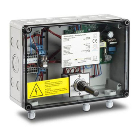
Deger MLD Control User manual

ASSEMBLY INSTRUCTIONS
MLD Control
Energy Converter 6 with Central Control Box

01/10/2021 ASSEMBLY INSTRUCTIONS MLD Control EC-6 with CCB III Page 2
© 2015
DEGERenergie GmbH & Co. KG
Industriestr. 70
D-72160 Horb am Neckar
Germany
info@DEGERenergie.com
ALL RIGHTS RESERVED. This manual contains material protected under International and Federal
Copyright Laws and Treaties. Any unauthorized reprint or use of this material is prohibited. No part of this
manual, including drawings and technical descriptions may be reproduced or transmitted in any form or by
any means, electronic or mechanical, including photocopying, recording, or by any information storage and
retrieval system without express written permission from the author / publisher.
We reserve the right for technical changes.
Version: 2018-12-12
Original version in German

01/10/2021 ASSEMBLY INSTRUCTIONS MLD Control EC-6 with CCB III Page 3
Contents
Abbreviations ................................................................................................................................................. 4
1General Information.................................................................................................................................... 5
1.1 MLD technology................................................................................................................................. 5
1.2 Introduction........................................................................................................................................ 6
1.3 Fundamental safety notes ................................................................................................................. 6
1.4 Exclusion of liability............................................................................................................................ 6
1.5 For your safety................................................................................................................................... 6
1.5.1 Intended purpose of the DEGER system ...................................................................................... 6
1.5.2 Personal protective equipment...................................................................................................... 6
1.6 Symbols used .................................................................................................................................... 7
1.7 Presentation of information................................................................................................................ 7
1.7.1 Lists and instructions ..................................................................................................................... 7
1.7.2 Notes on safety.............................................................................................................................. 7
2Energy Converter 6 (EC-6)......................................................................................................................... 8
2.1 EC-6: Pin assignment........................................................................................................................ 8
2.2 EC-6: Function................................................................................................................................... 9
2.3 EC-6: Default setting.......................................................................................................................... 9
2.4 EC-6: Changing configuration ......................................................................................................... 10
2.5 EC-6: LED display ........................................................................................................................... 11
3Central Control Box (CCB)....................................................................................................................... 12
3.1 CCB: Pin assignment....................................................................................................................... 12
3.2 CCB: Function ................................................................................................................................. 13
4Wind Monitor ............................................................................................................................................ 14
4.1 Wind monitor.................................................................................................................................... 14
4.1.1 Pin assignment ............................................................................................................................ 14
4.1.2 Port Description: .......................................................................................................................... 16
4.1.3 Display Interface:......................................................................................................................... 17
4.2 Anemometer Installation with Old Wind Monitor.............................................................................. 19
4.3 Assembly ......................................................................................................................................... 19
4.3.1 On building................................................................................................................................... 19
4.3.2 On the DEGER system................................................................................................................ 19
5Snow Sensor............................................................................................................................................ 22
5.1 Function........................................................................................................................................... 22
5.2 Assembly and positioning............................................................................................................... 22
5.3 Connection....................................................................................................................................... 23
6Connection ............................................................................................................................................... 24
6.1 Block diagram.................................................................................................................................. 24
6.2 Connection diagram......................................................................................................................... 25
6.2.1 CCB III with wind monitor ............................................................................................................ 25
6.2.2 CCB III with old wind monitor....................................................................................................... 25
6.3 Overview.......................................................................................................................................... 26
6.4 Places of installation........................................................................................................................ 27
7Start-up..................................................................................................................................................... 28

01/10/2021 ASSEMBLY INSTRUCTIONS MLD Control EC-6 with CCB III Page 4
8Clearance Check...................................................................................................................................... 28
8.1 Start of check................................................................................................................................... 28
8.2 Scope............................................................................................................................................... 28
9Technical Data.......................................................................................................................................... 29
9.1 EC-6................................................................................................................................................. 29
9.2 CCB ................................................................................................................................................. 29
9.3 Wind monitor.................................................................................................................................... 29
9.4 Climatic conditions........................................................................................................................... 29
10 Troubleshooting................................................................................................................................... 30
10.1 Troubleshooting diagram for energy converter................................................................................ 30
10.2 Fault report....................................................................................................................................... 31
11 Maintenance ........................................................................................................................................ 32
12 Cleaning............................................................................................................................................... 32
13 Decommissioning ................................................................................................................................ 32
13.1 Disassembly..................................................................................................................................... 32
13.2 Disposal........................................................................................................................................... 32
14 Appendix.............................................................................................................................................. 33
14.1 Conformity declaration..................................................................................................................... 33
14.2 TÜV certificate ................................................................................................................................. 34
15 Imprint.................................................................................................................................................. 35
Abbreviations
AZ = Azimuth (east-west orientation)
CCB III (Advanced) = Central Control Box with heated aluminum wind monitor
EC-6 = Energy converter 6 (part of the control)
EL = Elevation (angle of inclination)
EMO = Elevation drive (motor)
MLD = Maximum Light Detection
MLD Control = Energy converter, CCB, MLD sensors, wind monitor, snow sensor
OSHA = Occupational Safety and Health Administration
PPE = Personal protective equipment
SW = Spanner Width (wrench size)
UPS = Uninterruptible power supply

01/10/2021 ASSEMBLY INSTRUCTIONS MLD Control EC-6 with CCB III Page 5
uniformly diffuse light
1 General Information
1.1 MLD technology
DEGER’s patented MLD Control allows for accurate, quick and power-saving operation in orienting the
dual-axis DEGER systems to the position that has the most energy. This grants the MLD Control the
capability to obtain the greatest yield possible for a dual-axis mechanism. Two MLD sensors determine
which place in the sky has the greatest yield and move the module surfaces into this position. With the
DEGER system mechanism, the control can align the module surfaces to the sun accurately at all times
throughout the entire year. Not only does the control take into account the sun’s irradiation, it also accounts
for reflected light, for example, from snow, water or light-coloured rock, and for the diffuse irradiation
penetrating the clouds –and it does this individually for each system. In practice, this means that if clouds
move in from the west in the afternoon on an otherwise sunny day, the module surface will turn back to
face east based on irradiation. When there is full cloud coverage, the module surfaces will move either into
the horizontal position or into a position with higher irradiation so that the best yields can be obtained in any
weather situation. The control is designed to work in the most efficient way possible, and it moves only for
the purpose of directly increasing the yield.
Sunshine: The DEGER system directly faces the sun all day.
Varying light conditions: Because of different levels of cloudiness, the light conditions in solar parks vary for each DEGER
system. The individual control makes sure every DEGER system is optimally oriented to the brightest source of irradiation.
This guarantees the highest energy yield possible.
Snow, sand, gravel etc.
direct sunlight
diffuse light
Reflecting surface: The DEGER system
uses direct solar irradiation as well as
energy from reflected light.
Partly clouded: In addition to the direct
solar irradiation, diffused light is also
used to maximize the effects.
Overcast sky: The DEGER
systemcatches all the diffused light by
moving to a horizontal position.
direct sunlight
reflected light
uniformly diffuse light

01/10/2021 ASSEMBLY INSTRUCTIONS MLD Control EC-6 with CCB III Page 6
1.2 Introduction
These assembly instructions were created for the DEGER system. They are a component of the product and
must be saved for the entire lifespan of the DEGER system. The assembly instructions must be submitted
with the DEGER system should it be transferred to another party.
1.3 Fundamental safety notes
Read these assembly instructions in their entirety before starting assembly work and keep them available
at all times during the assembly process.
Only qualified personnel may perform assembly work.
Keep all objects out of the DEGER system’s range of pivoting motion throughout its full range of motion.
Take proper actions to protect the installed DEGER system in its full range of motion from unauthorised
access, such as enclosing it with a fence. Near the entry area to the DEGER system there must be a
warning sign stating that it is prohibited to remain within the range of pivoting motion.
Lightning protection and grounding must be installed in all photovoltaic systems according to country-
specific guidelines as stipulated in DIN VDE 0185 and 0100.
Do not operate the DEGER system if the wind monitor is not functioning. Always keep the module surface
in the SAFE position (table position) until the wind monitor has been tested for function.
1.4 Exclusion of liability
The General Terms and Conditions for Deliveries and Services (GTC) of DEGER are generally valid and
may be accessed on our website at www.DEGER.biz in the publisher information section. The contents of
these documents are continually checked and modified as needed. The assembly manual is also available
for downloading from the website www.DEGER.biz in the dealer section or can be ordered through the
normal sales channels.
Warranty and liability claims for any kind of damage are excluded if they can be traced back to any of the
following causes:
- Inappropriate or unintended use of the DEGER system and all parts of the MLD Control
- Operation of the DEGER system in an unintended environment
- Operation of the DEGER system while failing to comply with the locally valid statutory safety regulations
- Non-compliance with warnings and safety notes in all documents relevant to the product
- Operation of the DEGER system under unsound safety and protection conditions
- Unauthorized changes to the DEGER system's design, its component parts or their implementation in the
overall installation
- Unauthorized changes to the DEGER system
- Drilling holes in any housing, e.g. Central Control Box (CCB), Energy converter 6 (EC-6) and Evaluation
unit wind monitor (Use existing free holes for mounting the housings)
- Malfunction of the DEGER system caused by the effect of connected or adjacent devices beyond the
permissible limiting values
- Disaster situations and force majeure
- Installation of non-genuine DEGER replacement parts
- Unauthorized modifications to any parts
- Damages to any third party components (e.g. inverter or modules)
1.5 For your safety
1.5.1 Intended purpose of the DEGER system
The MLD control with EC-6 is intended only for the purpose of controlling DEGER systems.
DEGER systems can be used in the private and commercial sector. They are designed for outdoor
installation and for building integration.
1.5.2 Personal protective equipment
The customer must provide a sufficient amount of protective equipment for assembly and installation work.
Supervisors must check that this equipment is used.
The following protective equipment is required:
- Hard hat
- Safety shoes
- Safety gloves

01/10/2021 ASSEMBLY INSTRUCTIONS MLD Control EC-6 with CCB III Page 7
- Safety goggles
- When working at heights in excess of 1 m, anti-fall measures and PPE to protect against falling.
- Any and all safety equipment and standards to be in compliance with Federal, provinces, and local codes
and OSHA standards
1.6 Symbols used
The following symbols appear on the DEGER system and are used in the present document:
No unauthorised access
Read and follow the operating manuals and safety information before start-up
1.7 Presentation of information
1.7.1 Lists and instructions
Lists
Lists have bullet points:
- List
- List
Instructions in a certain order
Instructions that must be followed in a certain order are numbered:
1. Step 1
2. Step 2
Instructions without a certain order
Instructions that do not have to be followed in a certain order are listed with bullet points:
Instruction
Instruction
Results
Results of an action are indicated by a double arrow:
>> Result
1.7.2 Notes on safety
The following safety information is used in this document:
DANGER!
Direct endangerment with high risk, failure to comply will lead to fatal or severe physical injuries.
WARNING!
Possible endangerment with medium risk, failure to comply can lead to fatal or severe physical
injuries.
CAUTION!
Low risk endangerment, failure to comply can lead to medium physical injuries.
ATTENTION!
Danger of material damage, when failing to comply with this note.

01/10/2021 ASSEMBLY INSTRUCTIONS MLD Control EC-6 with CCB III Page 8
2 Energy Converter 6 (EC-6)
2.1 EC-6: Pin assignment
or
21
The clamping area on the M12 cable fitting is designed for a cable cross-section of 1 to 5 mm, while the
clamping area on the M16 cable fitting is designed for a cable cross-section of 2 to 7 mm.
Terminal
Function
Terminal
Function
1-2
Output EL Motor DC 24 V
Terminal 1 => Blue wire or wire 2, depending
on motor
Terminal 2 => Brown wire or wire 1, depending
on motor
11-12
Output MLD sensor for EL
Terminal 11 => Green wire
Terminal 12 => Yellow wire
3-4
Output AZ motor, DC +/-24 V
Terminal 3 => Blue wire
Terminal 4 => Brown wire
13-14
Output MLD sensor for AZ
- DC +/-23 V
Terminal 13 => Green wire
Terminal 14 => Yellow wire
20-21
Input SAFE POS (broken wire detection)
- DC +/-21 V
- DC +/-21 V
5-6
Input MLD sensor for EL
Terminal 5 => Brown wire DC +24 V
Terminal 6 => White wire DC 0 V
9-10
Output reserve DC 24 V, max. 1.1 A
7-8
Input MLD sensor for AZ
Terminal 7 => Brown wire DC +24 V
Terminal 8 => White wire DC 0 V
16-17
Input external EL from CCB
PE - L -
N
Input supply voltage
- AC 100 to 240 V
18-19
Input external AZ from CCB
EL motor
AZ motor
External CCB III
AZ MLD sensor
Grid connection
EL MLD sensor

01/10/2021 ASSEMBLY INSTRUCTIONS MLD Control EC-6 with CCB III Page 9
2.2 EC-6: Function
Priorities in operation: 1. Only one motor can be active (either AZ or EL), never both at the same time.
2. MLD sensors: AZ has priority over EL.
3. External inputs have priority over MLD sensors.
4. External EL input has priority over external AZ.
Reverse polarity function:
This function is used to make sure the module surface is within the transmission range of the MLD sensors in
any weather situation.
The reverse polarity function becomes activated when the same signal has been present at inputs 13-14 of
EC-6 for longer than 7 minutes. The reverse polarity function remains active for 6 minutes. Signals from the
MLD sensors are ignored during this time. The external inputs, joystick, broken wire detection and wind
monitor have priority. Jumpers can be used to deactivate the reverse polarity function.
Reverse direction function:
This function ensures the module surfaces are facing east the next morning to receive the first rays of
sunlight.
The AZ motor will switch on for 12 minutes once the EC-6 has not registered a signal at inputs 11-12 and 13-
14 for more than 4 hours. In the northern hemisphere, the system must rotate to the south; in the southern
hemisphere, it must rotate to the north. Either jumper J3 or J4 must be connected for this function.
The external inputs, joystick, broken wire detection, MLD sensors and wind monitor have priority. Jumpers
can be used to deactivate the reverse direction function.
SAFE POS (broken wire detection) function:
This function is used to compensate for any possible malfunctions (e.g., cable interruptions).
Continuous voltage of DC 24 V must be present at EC-6 inputs 20-21 for the control to function normally.
The EL motor output will be controlled continuously if the voltage signal is interrupted. The module surface
will move into the SAFE POS (table position). The SAFE POS output has top priority.
Jumpers can be used to deactivate the SAFE POS function.
2.3 EC-6: Default setting
Delivery for southern hemisphere: Delivery for northern hemisphere:
Jumpers J1, J2 and J3 are connected. Jumpers J1, J2 and J4 are connected.
J1: Reverse polarity ON J1: Reverse polarity ON
J2: SAFE POS function OFF J2: SAFE POS function OFF
J3: Reverse direction for southern hemisphere ON
J4: Reverse direction for northern
hemisphere ON
Jumper J2 must be connected to J7 for broken wire detection to be activated.

01/10/2021 ASSEMBLY INSTRUCTIONS MLD Control EC-6 with CCB III Page 10
2.4 EC-6: Changing configuration
DANGER!
Only trained and qualified personnel may make changes to the configuration by moving the
jumpers. The configuration may be changed by moving the jumpers only when no voltage is
present.
ATTENTION!
Some countries require there to be a broken wire detection function. We strongly recommend
using the broken wire detection function in all installed systems and checking it regularly for
proper function.
ATTENTION!
Changing the default settings will void any warranty claims.
Reverse direction Reverse direction Reverse direction
OFF: Southern hemisphere ON: Northern hemisphere ON:
J3: Must be open J3: Night function ON J3: Must be open
J4: Must be open J4: Must be open J4: Night function ON
J5: Night function OFF J5: Must be open J5: Must be open
Reverse polarity OFF: Reverse polarity ON:
J1: Must be open J1: Reverse polarity ON
J6: Reverse polarity OFF J6: Must be open
SAFE POS function OFF: SAFE POS function ON:
J2: SAFE POS function OFF J2: Must be open
J7: Must be open J7: SAFE POS function ON
Legend:
J1 connected: Reverse polarity ON
J2 connected: SAFE POS function OFF
J3 connected: Night function for southern
hemisphere ON
J4 connected: Night function for northern
hemisphere ON
J5 connected: Night function OFF
J6 connected: Reverse polarity OFF
J7 connected: SAFE POS function ON

01/10/2021 ASSEMBLY INSTRUCTIONS MLD Control EC-6 with CCB III Page 11
2.5 EC-6: LED display
EL motor active EL sensor active
Green LED Moving into inclined position Green LED Moving into inclined position
Red LED Moving into table position Red LED Moving into table position
LED off Motor is off LED off No signal from sensor
AZ motor active AZ sensor active
Green LED Moving to face west Green LED Moving to face west
Red LED Moving to face east Red LED Moving to face east
LED off motor is off LED off No signal from sensor
LED for motor voltage: Motor power OK
LED on DC 24 V motor voltage OK
LED for sensor voltage: Sensor power OK
LED on DC 24 V sensor voltage OK
ATTENTION!
If a motor is rotating in the opposite direction of that which is displayed by the LED lamps, switch
the connection cables for the motor from pin 1-2 to 3-4 or vice versa.

01/10/2021 ASSEMBLY INSTRUCTIONS MLD Control EC-6 with CCB III Page 12
3 Central Control Box (CCB)
3.1 CCB: Pin assignment
The clamping area on the cable fitting is designed for a cable cross-section of 3.5 mm to 7 mm.
Terminal
Function
Terminal
Function
20
Input (incline) DC 21 V
for snow sensor
A - B Vin
Input supply voltage
- DC 80 to 380 V
- AC 100 to 265 V
21
N/A
1 - 2
Output for EC-6 DC +/-21 V
EL axis
22
Input
from wind monitor
Wire Green
3 - 4
Output for EC-6 DC +/-21 V
AZ axis
23
Broken Wire Detection from Wind Monitor
GND
N/A
+ / -
Voltage supply DC 21 V, max. 1.4 A
for snow sensor and wind monitor
Red Wire of Wind Monitor
WH
N/A
2
1
2
0
2
2
2
3
Relay for
wind
monitor
Basic
(only for
CCB II)
open
open
open
open

01/10/2021 ASSEMBLY INSTRUCTIONS MLD Control EC-6 with CCB III Page 13
3.2 CCB: Function
General:
One CCB can be used to control up to 100 DEGER systems from a central location.
Joystick:
Automatic mode is deactivated once the joystick is operated. Any system connected to the CCB will move in
the direction indicated by the joystick.
For example, the modules can all be set flat, for maintenance work (mowing grass), or at a steep incline, for
manual snow removal.
The system will switch back to automatic mode once the joystick is returned to the neutral position (0).
Wind monitor + snow sensor:
A wind monitor and snow sensor do not have to be installed on every DEGER system when a CCB is used
in a solar energy plant that has several systems. One snow sensor and one wind monitor can be used for up
to 100 DEGER systems.
Inclined position
Table position
AZ
AZ

01/10/2021 ASSEMBLY INSTRUCTIONS MLD Control EC-6 with CCB III Page 14
4 Wind Monitor
4.1 Wind monitor
The wind alarm becomes activated when the wind speed exceeds continuously the default setting of 12 m/s.
The alarm will stop when the wind speed is continuously slower than the default setting of 10 m/s for a
duration of approximately 10 minutes. If the wind speed exceeds 10 m/s within these 10 minutes, the time
will start over for another 10 minutes.
Speed [ m/s ]
Relay is deactivated
Wind alarm Wind alarmstops
12m/s
10m/s
1s 10 min
Time [ ]
Relay is reactivated
The alarm can be cancelled early by unlocking the power reset
4.1.1 Pin assignment
Note: If you have our old wind monitor with our new anemometer, then please refer to page 19 & 25 for
installation
Terminal
designation
Function
AC Power
Supply
Supply voltage
- AC 100 to 240 V
- 1.1 A
Red and Blue Wires
22
Switch contact for wind alarm, potential-free
Green Wire
Connection for CCB
+
Switch contact for wind alarm, potential-free
Red Wire
Connection for CCB
Evaluation unit
CCB
Cable length 20 m

01/10/2021 ASSEMBLY INSTRUCTIONS MLD Control EC-6 with CCB III Page 15
ATTENTION!
The cable for the power supply connection must be routed underneath the power supply.
The primary wire may not be routed on the same side as the secondary wires. Primary and
secondary wires should never be routed together.
The cable of the anemometer can be extended up to 100 m.

01/10/2021 ASSEMBLY INSTRUCTIONS MLD Control EC-6 with CCB III Page 16
4.1.2 Port Description:
In this section more information on the wind monitor hardware will be explained.
As can be seen above, we have 3 points of connections in DEGER wind monitor:
Sensor Connection: The anemometer connector should be connected to the sensor connection
port. The anemometer comes with 20m cable. It is advised to install the anemometer within 20m
range. If range is more than 20m, then the customer needs to be very careful regarding extension of
cable.
Relay Output: The relay output connection already comes with a 1.5m cable. The customer can
extend it easily as only 2 wires needs to be connected to CCB III terminals 22 and +. The Red wire
will be connected to + terminal and Green wire to 22 terminal of CCB III.
Input: The input port also comes with a 10m cable. The user can extend the cable if required. User
can provide AC/DC power supply. Please refer to specifications when providing AC/DC power
supply.
4.3 inch wind speed display
Power switch
Relay Output: NO & NC
Sensor connection
Input: 220VAC 50/60HZ
Output: DC12V----2.0A

01/10/2021 ASSEMBLY INSTRUCTIONS MLD Control EC-6 with CCB III Page 17
4.1.3 Display Interface:
In this section, information will be provided on different options of our DEGER wind monitor software:
Main Interface: The main interface shows the following information:
a. Wind Speed: It shows the wind speed from rotation of anemometer in m/s.
b. Alarm of Wind Speed: Shows the wind speed at which the alarm will start and the tracker
will move to safe position.
c. Time Interval: This shows after how many minutes it stores the data.
d. WS Chart: This shows the user a graph of wind speeds over the whole day.
e. History: This shows the saved wind speeds at different times of the day.
f. Set Up: It has more options to choose from which will be discussed later.
Main Interface
Note: The alarm of wind speed and time interval is locked with a password. This can only be set by
a DEGER team member.
Wind Speed Chart Interface: When user clicks on WS Chart button, they will see the graph shown
below.
WS Chart
As seen above the graph shows different wind speeds on vertical axis and the corresponding time
shown on horizontal axis of graph.

01/10/2021 ASSEMBLY INSTRUCTIONS MLD Control EC-6 with CCB III Page 18
History Interface: When user clicks on History button, they will see the interface shown below.
Figure 5: History
As shown above, this stores the wind speed information with corresponding time and date. Default interval
time is 5 minutes. The interval time is shown on main screen and can be set only by a DEGER team
member.
Setting Interface: Entering the setting interface through the main interface, the user will see the interface
shown below:
Settings
In settings interface, the user can turn on or off the touch sound, set the screen saver time, can calibrate
according to coordinate and set local time. Another feature is that user can also see the wind alarm records
by clicking on wind speed alarm as shown in image above.
Alarm Record Interface: The alarm record interface records all the wind alarms with corresponding date
and time as shown below in image. User also has the option to delete the history of wind alarm records when
space gets full.
Wind Alarm Records

01/10/2021 ASSEMBLY INSTRUCTIONS MLD Control EC-6 with CCB III Page 19
4.2 Anemometer Installation with Old Wind Monitor
The anemometer having 3 wires ( Red, Yellow & Black ) should be connected to old wind monitor as shown
below:
Anemometer
Old Wind Monitor
Red Wire
Terminal +
White Wire
Terminal 35
Black Wire
Terminal -
4.3 Assembly
4.3.1 On building
ATTENTION!
The anemometer must be installed perpendicular and minimum at the height of the upper edge of
the module surface in a location where it is exposed to wind.
The anemometer should not be installed in the wind shadow of objects.
4.3.2 On the DEGER system
The only way a DEGER wind monitor (anemometer) can be attached directly to a DEGER system is by
installing the optionally available pendulum kit of DEGER. The pendulum kit can be used with all DEGER
wind monitors.
ATTENTION!
The cable for the anemometer must be routed in such a way that it will not be damaged by
the nodal bar. If the cable becomes damaged, it will pose a danger by preventing the module
surface from moving into the SAFE position (table position) when the wind speed is too high
(except for when the broken wire detector is connected).
1. The pre-assembled pendulum kit has to be fastened to the DEGER system on the left side of the module
surface, when viewed from the rear, using the aluminum profile F-SET-X. The distance between outer edge
of module and nodal bar must be 200 mm.

01/10/2021 ASSEMBLY INSTRUCTIONS MLD Control EC-6 with CCB III Page 20
DEGER 3000NT and 3000HD
The endclamp and bolts are adapted to the module
height. These parts are delivered separately and
are not included in the accessory pack.
For this purpose the aluminum profile F-SET-X of
the pendulum kit has to be fastened to the top
module row with one clamp plate, bolt M6 and
sliding nut M6 as well as one endclamp, bolt M8
and sliding nut M8.
If necessary, extend the F-Set-X by using the
profile connector.
Torque M6: 8 Nm
Torque M8: 20 Nm
Torque M10: 38 Nm
20cm
Solar module
Aluminum
profile
Aluminum
profile
Solar
module
Profile connector
Table of contents
Other Deger Controllers manuals
