Feniex 4200-DL User manual

FENIEX. 2017 INSTRUCTION MANUAL
WEB. www.feniex.com
Feniex Product Copyrights This price List and the mentioned Feniex products include or describe copyrighted Feniex material. Laws in the
United States and other countries preserve for Feniex Industries and its licensors certain exclusive rights for copyrighted material, including the
exclusive right to copy, reproduce in any form, distribute and make derivative works of the copyrighted material. Accordingly, any copyrighted
material of Feniex and its licensors contained herein or in the Feniex products described in this Price List may not be copied, reproduced,
distributed, merged or modied,transmitted, transcribed, stored in retrieval system or translated into any language or computer language, in any
form or by any means, without prior written permission of Feniex Industries, Inc.. Feniex and the stylized Feniex logo are registered in the U.S.
Patent & Trademark Oce.
This instruction manual serves as a
guide for the 4200-DL Controller.
IMPORTANT! Please read through all
provided instructions and any listed
warnings in regards to product use.
4200-DL Controller
Instruction Manual
V.2.0
4200-DL
Model # C-4200-DL

TM
FENIEX. 2017 INSTRUCTION MANUAL
WEB. www.feniex.com
2
Table of Contents
Safety Regulations & Warranty 3
Service after Expiration 3
Copyright 3
Feniex Product Copyright 3
Box Contents 4
System Specication 5
Control Head Mounting 6
Vertical Mount 6
Surface Mount 6
Relay Wiring Diagram 7
Conguration Record 9
Conguration Record Diagram 10
Control Head Programming 11
Help 11
Bluetooth 19
Bluetooth Hardware 19
Bluetooth Software 20
4200 App Requirements 20
FAQ 21
V2.0

Operational times are from 10 a.m. to 5 p.m.
central time, Monday through Friday. Please
do not send in product without contacting
support rst for a RMA number.
Service After Expiration
Feniex Industries will still provide service for
all products after expiration of the warranty.
For any issues, call the customer support
line. In some instances it may be necessary
for the product to be shipped, freight prepaid
and insured for loss or damage to Feniex
headquarters.
Copyright
This instruction manual and the Feniex
products described in this instruction
manual may include or describe copyrighted
Feniex material. Laws in the United States
and other countries preserve for Feniex
Industries and its licensors certain exclusive
rights for copyrighted material, including
the exclusive right to copy, reproduce in
any form, distribute and make derivative
works of the copyrighted material.
Accordingly, any copyrighted material of
Feniex and its licensors contained herein
or in the Feniex products described in this
instruction manual may not be copied,
reproduced, distributed, merged or modied
in any manner without the express written
permission of Feniex Industries, Inc.
Feniex Product Copyrights
The products described in this document
are the property of Feniex Industries, Inc. It is
furnished by express license agreement only
and may be used only in accordance with the
terms of such an agreement. Products and
documentation are copyrighted materials.
Making unauthorized copies is prohibited by
law. No part of the product or documentation
may be reproduced, transmitted, transcribed,
stored in retrieval system or translated into any
language or computer language, in any form or
by any means, without prior permission from
Feniex Industries, Inc.
Safety Regulations
The following provides all the information
necessary to safely operate the previously
listed products of Feniex Industries, Inc.
Please read this manual thoroughly before
installing or operating your new product
in order to prevent any damage or injury.
Failure to follow the listed instructions in
this manual may result in damage to your
products or personal injury.
• Proper installation of this product
requires good knowledge of automotive
systems, electronics and procedures.
• Please guarantee all vital components
of the vehicle are not in danger of being
damaged by drilling holes necessary
for installation. Check all sides of the
mounting surface before drilling any
holes into the vehicle.
• Do not install this product in any way
that interferes with the deployment of
the air bag. Doing so may damage the
eectiveness of the air bag and can
lead to serious personal and vehicle
injury. The installer will assume full
responsibility of proper installation of the
new unit.
• Please clean the mounting surface
before installation of the unit when using
tape, brackets, magnet, Velcro or suction
cups.
• The product's ground wire must be
connected directly to the Negative (-)
battery post for eective use of the
unit. Please follow all wiring guidelines
provided to guarantee long lifespan
and productivity. Failing to follow these
instructions may result in damage to the
product.
Warranty
Feniex Industries, Inc. warrants to the original
purchaser that the product shall be free
from defects in material and workmanship
for 5 years from the date of purchase for all
LED products. Feniex Industries warranties
speakers, sirens, ashers, and controllers for
2 years.
If a warranty problem occurs, please contact
customer support at 1.800.615.8350 or
visit the web site at www.Feniex.com. If the
product needs to be returned for repair or
replacement, call our customer support line
to receive a return merchandise authorization
number.
Warning! Utilizing non-factory screws and mounting
brackets may result in loss of warranty coverage.
TM
FENIEX. 2017 INSTRUCTION MANUAL
WEB. www.feniex.com 3
Safety Regulations & Warranty
V2.0

TM
FENIEX. 2017 INSTRUCTION MANUAL
WEB. www.feniex.com
4
Slide Switch
U-Shaped
Bracket
USB
Cable
RJ45
Cable
Legend/
Label Sheets
Box contents
RJ45
Cable
4200 Relay
V2.0

TM
FENIEX. 2017 INSTRUCTION MANUAL
WEB. www.feniex.com
5
System Specification
Below you will nd the key specications for the 4200-DL system. Review the information
to better determine your installation needs.
Warning! Do not deviate from the specied voltage.
System Specication:
Input Voltage: 11VDC to 16VDC
Temperature Range: -40C° to +70CV°
Stand By Current: > 100m Amps
Logic Input A-B Ground
Logic Input C-D-E Positive
Logic Input F Night Mode (+)
Logic Input G Day Mode (+)
Logic Input H Ignition (+)
Output 1-2 WigWag 10 Amps (+)
Outputs 3-20 10 Amps (+)
Max Input Current 60 Amps
Controller Dimensions 6.8″ x 3.5″ 1.3″
Power Supply Dimensions 6.33" x 3.3" x 1.48"
Bluetooth Range 40ft (+/- 5ft)
V2.0
TM
FENIEX. 2017 INSTRUCTION MANUAL
WEB. www.feniex.com
6
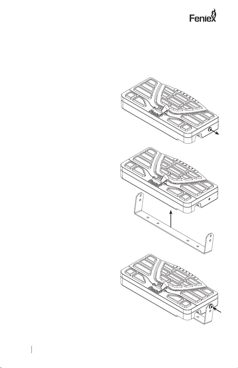
Control Head
Decide which mounting option you would like to implement for the 4200 controller:
Option A is a vertical mount, allowing the controller to hang down. Option B is a surface
mount; with the bracket mounting from the rear of the controller. The controller can
also be mounted with a custom face on a console mount. Please contact your preferred
console manufacturer for a 4200 console faceplate (option not shown).
Option A: Vertical Mount
Step 1: Select a dry, cool location to mount
the control head
Step 2: Remove the two factory provided
screws located on either side of the
controller.
Step 3: Place the U-Shaped bracket into
place and screw the two factory provided
screws back on each side of the controller.
Step4.ConnecttheRJ45cabletotheRJ45port
located on the rear of the controller.
Option B: Surface Mount
Step 1: Mount the U-Shaped Bracket in the
desired location using 2 self-tapping screws.
If you wish to use machine screws, simply
drill out the required hole size based on the
size of screw choice.
Important! Make sure not to damage any
vital parts of the vehicle or mounting
surface. Do not mount anywhere that
interferes with the vehicle air bag.
Step 2: Re-attach the control panel head to
the U-Shaped bracket utilizing the factory
provided screws.
Step 3. Connect the RJ45 cable to the RJ45
port located on the rear of the controller.
V2.0

TM
FENIEX. 2017 INSTRUCTION MANUAL
WEB. www.feniex.com
7
relay wiring Diagram
Fusion Lightbar
49" or 60"
Storm Siren
Storm Siren
A = 12V-
B = 12V-
C = 12V+
D = 12V+
E = 12V+
F = night
G = day
H = lightion
Controller
RJ45
60 Amp Fuse
12V+ post
12V- post
Battery
10 Amps WigWag
10 Amps WigWag
12V+
12V+
12V+
12V+
12V+
12V+
12V+
12V+
12V+
12V+
12V+
12V+
12V+
12V+
12V+
12V+
12V+
12V+
12V- 12V+
The below is an example illustration of an installation with the 4200
Not provided, install
6 inches away from the battery post.
[
]
2 X 100W
or 100W + 200W
Output
1 - 4
Output
5 - 8
Output
9 - 12
Output
13 - 16
Output
17 - 20
Recommended
10-12 AWG Wire
USB
use either RJ45 or USB
cable at one time.
Warning! Utilizing non-
factory screws and mounting
brackets may result in loss of
warranty coverage.
Warning! Any Storm unit with the below
label is not compatible with the 4200
Data link model. Do not connect the
RJ45 port on this unit to a 4200 datalink
unit
V2.0
TM
FENIEX. 2017 INSTRUCTION MANUAL
WEB. www.feniex.com
8
Controller
RJ45
F1
F2
F3
F4
F5
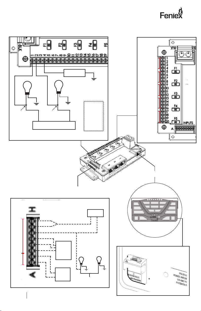
relay wiring Diagram
Output Power
Halogen or LED Light
BCM
connect
here
connect
here
Fog
Headlight
Tail
Turn
Brake
Load/Device
12V+
12V-
BCM
Ignition
Day
Night (optional)
+
Input Section
headlight
12V-
e.g:
Park Kill
12V+
e.g:
Park Kill or
High Beam
Override
A
B
C
D
E
F
G
H
Important!
Only use either RJ45
or USB at one time.
The below image shows the location of
the X5, 30 amp Fuses on the relay.
The below image indicates the use of outputs 1 and 2 for wig wag
functionality.
The below image illustrates the multiple, potential functionality for
inputs A-H.
Output 1-4
Output 5-8
Output 9-12
Output 13-16
Output 17-20
+
wig wag
V2.0

TM
FENIEX. 2017 INSTRUCTION MANUAL
WEB. www.feniex.com
9
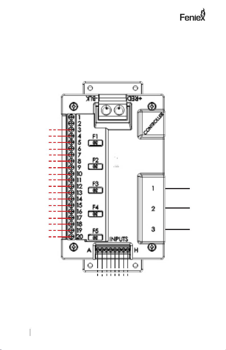
Use this document to record the products connected to each outlet to assist when
programming the control head with the provided software package.
Outputs: Buttons: (1 - 18, P1 - P3)
3
4
5
6
7
8
9
10
11
12
13
14
15
16
17
18
19
20
Inputs: Outputs / Buttons:
A (-)
B (-)
C (+)
D (+)
E (+)
Configuration Record
F (+Night)
G (+Day)
H (+Ignition)
V2.0
TM
FENIEX. 2017 INSTRUCTION MANUAL
WEB. www.feniex.com
10
Configuration Record diagram
V2.0
Other manuals for 4200-DL
1
Table of contents
Other Feniex Controllers manuals


Popular Controllers manuals by other brands

Digiplex
Digiplex DGP-848 Programming guide

YASKAWA
YASKAWA SGM series user manual

Sinope
Sinope Calypso RM3500ZB installation guide

Isimet
Isimet DLA Series Style 2 Installation, Operations, Start-up and Maintenance Instructions

LSIS
LSIS sv-ip5a user manual

Rockwell Automation
Rockwell Automation 1769-L31 installation instructions


