Deger MLD Control Energy Converter S1 User manual
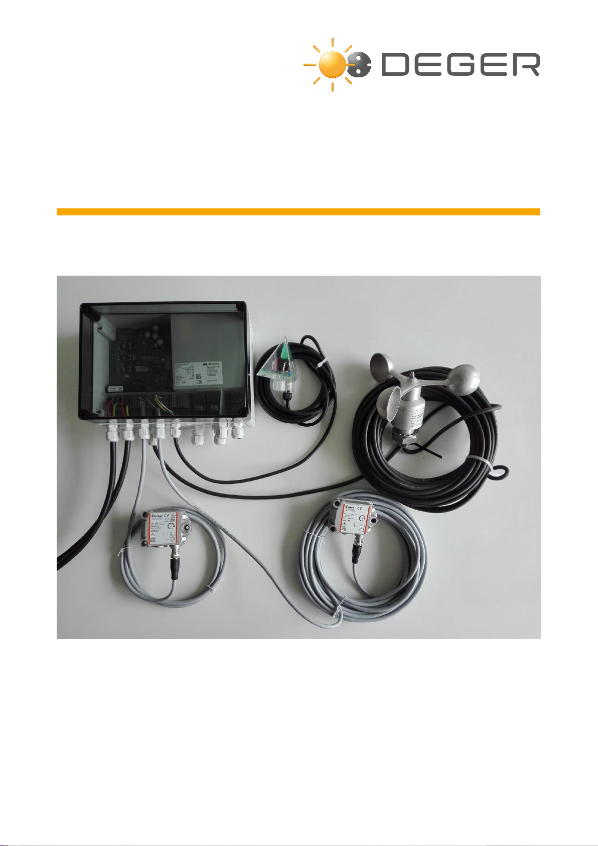
MLD Control
Energy Converter S1
S100-DR S100-SR
ASSEMBLY INSTRUCTION

27.06.2019 ASSEMBLY INSTRUCTIONS MLD CONTROL EK-S1 Page 2
Copyright
All information presented in this technical document and the drawings and technical descriptions made
available by DEGER remain the property of DEGER and may not be reproduced without prior explicit written
permission from DEGER.
We reserve the right to make technical changes.
Version: 2019-06-27

27.06.2019 ASSEMBLY INSTRUCTIONS MLD CONTROL EK-S1 Page 3
List of contents
Abbreviations ................................................................................................................................................. 5
1Introduction................................................................................................................................................. 6
1.1 Basic safety information..................................................................................................................... 6
1.2 Exclusion of liability............................................................................................................................ 6
1.3 For your safety................................................................................................................................... 6
1.3.1 Intended purpose of the DEGER system ...................................................................................... 6
1.3.2 Personal protective equipment...................................................................................................... 6
1.4 Symbols used .................................................................................................................................... 7
1.5 Presentation of information................................................................................................................ 7
1.5.1 Lists and instructions ..................................................................................................................... 7
1.5.2 Safety information.......................................................................................................................... 7
2Energy Converter S1 (EK-S1).................................................................................................................... 8
2.1 EK-S1 Functions................................................................................................................................ 8
2.2 EK-S1: Cable connections................................................................................................................. 8
2.3 EK-S1: Pin assignments.................................................................................................................... 9
2.4 EK-S1 LED –display...................................................................................................................... 10
2.4.1 LED’s indicating main functions:.................................................................................................. 10
2.4.2 LED assignments......................................................................................................................... 11
3Manual Control......................................................................................................................................... 12
3.1 Joystick Functions ........................................................................................................................... 12
3.2 Pin assignment ................................................................................................................................ 12
4Wind Guard .............................................................................................................................................. 13
4.1 Wind guard....................................................................................................................................... 13
4.2 Assembly ......................................................................................................................................... 13
4.3 Connection....................................................................................................................................... 13
5Snow Sensor............................................................................................................................................ 14
5.1 Function........................................................................................................................................... 14
5.2 Positioning ....................................................................................................................................... 14
5.3 Assembly ......................................................................................................................................... 15
5.4 Connection....................................................................................................................................... 15
6Connections.............................................................................................................................................. 16
6.1 Block diagram.................................................................................................................................. 16
6.2 CAN-Bus.......................................................................................................................................... 17
6.2.1 CAN-Bus connections EK-S1...................................................................................................... 17
6.2.2 Connecting CAN-Bus to the management PC ............................................................................ 17
6.3 Uninterruptible power supply for a DEGER sytem .......................................................................... 18
7Start-up..................................................................................................................................................... 19
8Clearance Check...................................................................................................................................... 20
8.1 CTC manual control......................................................................................................................... 20
8.2 Joystick............................................................................................................................................ 20
8.3 Battery pack..................................................................................................................................... 20
9Technical Data.......................................................................................................................................... 21
9.1 Electrical ratings..................................................................................................................................... 21

27.06.2019 ASSEMBLY INSTRUCTIONS MLD CONTROL EK-S1 Page 4
9.2 Electrical norms...................................................................................................................................... 21
9.3 Climatic conditions................................................................................................................................. 21
9.4 General .................................................................................................................................................. 21
10 Troubleshooting................................................................................................................................... 22
10.1 Error Recognition & Removal.......................................................................................................... 22
10.2 Fault Report..................................................................................................................................... 24
11 Maintenance ........................................................................................................................................ 25
12 Cleaning............................................................................................................................................... 25
13 Decommissioning ................................................................................................................................ 26
13.1 Disassembly..................................................................................................................................... 26
13.2 Disposal........................................................................................................................................... 26
14 Conformity Declaration........................................................................................................................ 27
15 Publisher Information........................................................................................................................... 28

27.06.2019 ASSEMBLY INSTRUCTIONS MLD CONTROL EK-S1 Page 5
Abbreviations
EL = Elevation (east-west orientation)
CTC = Central Tracker Control (software)
EK-S1 = Energy Converter S1
MLD = Maximum Light Detection
MLD Control = Energy Converter, MLD sensor, wind sensor, snow sensor
PPE = Personal Protective Equipment
UPS = Uninterruptible power supply

27.06.2019 ASSEMBLY INSTRUCTIONS MLD CONTROL EK-S1 Page 6
1 Introduction
These assembly instructions were created for the DEGER system. They are a component of the product and
must be saved for the entire lifespan of the DEGER system. The assembly instructions must be included with
the DEGER system should it be transferred to another party.
1.1 Basic safety information
Read these assembly instructions in their entirety before starting assembly work and keep them available
at all times during the assembly process.
Only qualified personnel may perform assembly work.
Keep all objects out of the the DEGER system’s full range of pivoting motion throughout its full range of
motion.
Take necessary actions to protect the installed DEGER system in its full range of motion from unauthorized
access, such as enclosing it within a fence. Near the entry area to the DEGER system there must be a
warning sign stating that it is prohibited to remain within the range of pivoting motion.
Lightning protection and grounding must be installed in all photovoltaic systems according to country-
specific guidelines as stipulated in DIN VDE 0185 and 0100.
Do not operate the DEGER system if the wind guard is not functioning. Always keep the module surface in
the SAFE position (table position) until the wind guard has been tested for function.
If snow has accumulated on the module surface, the module surface must first be cleared. This is
accomplished by manually control via the CTC software or through the snow sensor. If no functioning CTC
remote access and/or snow sensor is available, the module surface must be cleared manually. The snow
sensor availability shall not release the module surface from the obligation to be cleared of snow.
DEGER recommends an Uninterruptible Power Supply (UPS) to ensure the function of the wind monitor.
1.2 Exclusion of liability
As a rule, DEGER’s General Terms and Conditions shall apply. The contents of these documents are
checked continuously and modified as needed. The assembly instructions are available for download in the
dealer section on the website, www.DEGER.biz, and they can also be obtained through the traditional
distribution channels.
Warranty and liability claims will be void if any type of damage occurs that results from one or more of the
following causes:
- Improper or unauthorized use of DEGER system
- Operation of DEGER system in an improper environment
- Operation of DEGER system without taking into account the statutory safety regulations applicable at the
place of installation
- Non-observance of warnings and safety information in all documents relevant to the product
- Operation of DEGER system in the absence of proper safety and protective measures
- Unauthorized modifications to DEGER system
- Drilling holes in any housing, e.g. EK-S1. Use existing free holes for mounting the housings.
- Failure of the DEGER system due to the influence of connected or neighbouring devices outside of the the
permitted limits
- Catastrophes and force majeure
1.3 For your safety
1.3.1 Intended purpose of the DEGER system
The MLD control with EK-S1 is intended only for the purpose of controlling DEGER’s system.
DEGER’s system can be used in the private and commercial sector. They are designed for outdoor
installation and for building integration.
1.3.2 Personal protective equipment
The client must provide enough safety equipment for assembly and maintenance work. Supervisors must
ensure safety equipment is worn.
The following safety equipment is mandatory:
- Protective helmet
- Safety shoes
- Safety gloves
Fall protection equipment and PPE to prevent falling when working more than 1 m above the ground
27.06.2019 ASSEMBLY INSTRUCTIONS MLD CONTROL EK-S1 Page 7
1.4 Symbols used
The following symbols appear on the DEGER system and are used in the present document:
No unauthorized access
Read and follow the operating manuals and safety information before start-up
1.5 Presentation of information
1.5.1 Lists and instructions
Lists
Lists have bullet points:
- List
- List
Instructions in a certain order
Instructions that must be followed in a certain order are numbered:
1. Step 1
2. Step 2
Instructions without a certain order
Instructions that do not have to be followed in a certain order are listed with bullet points:
Instruction
Instruction
Results
Results of an action are indicated by a double arrow:
>> Result
1.5.2 Safety information
The following safety information is used in this document:
______________________________________________________________________________________
DANGER!
Imminent danger with a high risk; failure to observe will lead to severe physical injury or death.
______________________________________________________________________________________
WARNING!
Possible danger with a moderate risk; failure to observe can lead to severe physical injury or death.
______________________________________________________________________________________
CAUTION!
Danger with low risk; failure to observe can lead to moderate physical injury.
______________________________________________________________________________________
NOTE!
Failure to observe this information entails the risk of property damage.
_____________________________________________________________________________________

27.06.2019 ASSEMBLY INSTRUCTIONS MLD CONTROL EK-S1 Page 8
2 Energy Converter S1 (EK-S1)
2.1 EK-S1 Functions
The EK-S1 is intended to be connected via CAN-Bus to other EK-S1’s and a PC and operated with the
Central Tracker Control (CTC) software from the PC.
For the CTC a separate manual (the CTC User Guide) is available.
Applies in general: 1. External input from CTC (manual control) has priority over MLD sensor.
2. External input from wind sensor has priority over external manual control.
Reverse direction function:
This function ensures the module surface is facing east the next morning to receive the first rays of sunlight.
The motor will switch on for 12 minutes once the EK-S1 has not registered a signal at terminal XG1 for more
than 4 hours. The external inputs, joystick, MLD sensor and wind monitor have priority.
2.2 EK-S1: Cable connections
The EK-S1 is delivered with prewired MLD-sensor, Inclination sensor cabling and motor cabling. PG glands
for the CAN-Bus (M20) and AC power (M16) will be pre-installed.
The PG glands for the wind guard (M20) and the snow sensor (M16) are only needed one time in every
installation and are included as an accessory.
PG glands for the UPS and theft protection (both M16) can be provided on request.
______________________________________________________________________________________
CAUTION!
Please observe the right polarity of the motor cables if disconnecting these during installation.
Reverse polarity can lead to serious damage of the system.
______________________________________________________________________________________
Note!
All PG glands must fit with the installed cables from customer side and must hermetically seal the
housing to avoid moisture inside. Underground slave cables must be laid in a cable conduit.
Motor 1
Master
Motor 2
Slave
Inclination sensor
Slave
Inclination sensor
Master
MLD sensor
CAN Bus
In
Snow sensor
Reserve
(option)
AC Power
In
AC Power
Out
Wind guard
(anemometer)
CAN Bus
Out
UPS
(option)
Theft protection
(option)
27.06.2019 ASSEMBLY INSTRUCTIONS MLD CONTROL EK-S1 Page 9
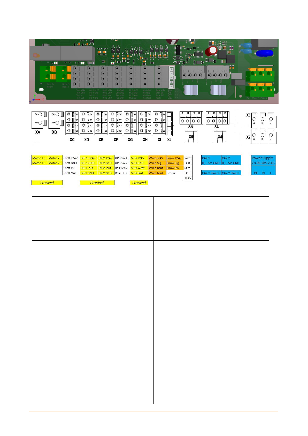
2.3 EK-S1: Pin assignments
Terminal
Function
Wire code
Terminal
Function
Wire code
XA
XB
Drives 24 Vdc
Pin A => Motor 1+ Master
Pin B => Motor 1- Master
Pin A => Motor 2+ Slave
Pin B => Motor 2- Slave
Blue
Red
1 (Blue)
2 (Red)
XH
Wind Sensor
Pin A: => (+24V)
Pin B: => Wind Signal
Pin C: => Wind Heat
Pin D: => Wind Heat
Wire 5
Wire 4
Wire 1
Wire 2
XC
Theft Protection (optional)
Pin A => (+24V)
Pin B => (GND)
Pin C => (IN)
Pin D => (OUT)
User
defined
XI
Snow Sensor
Pin A: => (+24V)
Pin B: => Snow Signal
Pin C: => GND
Reserve IN
Brown
Black
Blue
XD
Inclination Sensor Master
Pin A => Master (+24V)
Pin B => Master (GND)
Pin C => Master Current (Iout)
Pin D => Master (GND)
Brown
White
Green
XJ
Manual Control (Joystick)
Pin 1: => West
Pin 2: => East
Pin 3: => Horizontal Safe
Pin 4: => On
Pin 5: => (+24V)
Plug
XE
Inclination Sensor Slave
Pin A => Slave (+24V)
Pin B => Slave (GND)
Pin C => Slave Current (Iout)
Pin D => Slave (GND)
Brown
White
Green
XK
CAN Bus In
Pin A: => CAN High
Pin B: => CAN Low
Pin C: => (+5V)
Pin D: => GND
User
defined
XF
Uninterruptible Power Supply
(optional)
Pin A => Switch 1,
Pin B => Switch 2
Pin C => Reserve (+24V)
Pin D => Reserve (GND)
User
defined
XL
CAN Bus Out
Pin A: => CAN High
Pin B: => CAN Low
Pin C: => (+5V)
Pin D: => GND
User
defined
XG
MLD Sensor
Pin A: => MLD (+24V)
Pin B: => MLD GND
Pin C: => MLD West
Pin D: => MLD East
Brown
White
Yellow
Green
X2
X3
Power (100 –265 VAC)
Pin A: => PE -Potential Earth
Pin B: => N - Phase Neutral
Pin C: => L - Phase Live
Country
Specific

27.06.2019 ASSEMBLY INSTRUCTIONS MLD CONTROL EK-S1 Page 10
2.4 EK-S1 LED –display
2.4.1 LED’s indicating main functions:
DG1 - Wind sensor DD1 –Snow sensor
Green LED
wind ok Green LED
snow ok
Red LED
wind alarm Red LED
snow alarm
LED off
no sensor present LED off
no sensor present
DA 1 –Master motor active DB 1 –Slave motor active DC 1 - MLD sensor active
Green LED
moving to face west Green LED
Irradiation west predominant
Red LED
moving to face east Red LED
Irradiation east predominant
LED off
motor is off LED off
no signal from sensor
D29 –Inclination sensor Slave
LED on: sensor ok
Flashing: sensor error
D31 –Inclination sensor Master
LED on: sensor ok
Flashing: sensor error

27.06.2019 ASSEMBLY INSTRUCTIONS MLD CONTROL EK-S1 Page 11
2.4.2 LED assignments
Part Code
Assignment
Function
Multi-
Color-
LED
DA1
Motor 1 (Master) active
Green: Moving to face west
Red: Moving to face east
LED off: motor is off
X
DB1
Motor 2 (Slave) active
Green: Moving to face west
Red: Moving to face east
LED off: motor is off
X
DC1
MLD sensor
Green: Irradiation west predominant
Red: Irradiation east predominant
X
DD1
Snow sensor
Off: No sensor registered on EK-S1
Green: Sensor connected and OK
Red: Snow alarm activated
Red Slow Flash: Moving to unload position
Red Fast Flash: Sensor fault
X
DE1
Joystick manual control
Red: Joystick plugged in and active
Red Fast Flash: Joystick error
X
DF1
CTC manual control
Green: CTC move to face west
Red: CTC move to face east
Off: No command from CTC
X
DG1
Wind sensor
Off: No sensor registered on EK-S1
Green: Sensor connected and OK
Red: Wind alarm activated
Red Slow Flash: Waiting for wind alarm end
Red Fast Flash: Sensor fault
X
D29
Inclination sensor Slave
On: Sensor ok
Flashing: Sensor error
D31
Inclination sensor Master
On: Sensor ok
Flashing: Sensor error
D35
Motor 2 (Slave)
Off: Motor ok
On: Motor error, defective
Flashing: Motor waits until next attempt
D41
Motor 1 (Master)
Off: Motor ok
On: Motor error, defective
Flashing: Motor waits until next attempt
D43
System status (Overload)
Off: System status ok
On: Excessive heat, Motor stopped
Flashing: System waits for ok
D64
Controller power
On: Microcontroller voltage ok
Fast Flash: Power error
D65
MLD sensor power
On: MLD sensor voltage ok
Fast Flash: Power error
D66
Motor power
On: Motor voltage ok
Fast Flash: Power error
D67
CAN-Bus power
On: Bus voltage ok
Slow Flash: Data transfer
Fast Flash: Power error
For interpretation of LED states and resulting actions in case of faults see Section 10 Troubleshooting
27.06.2019 ASSEMBLY INSTRUCTIONS MLD CONTROL EK-S1 Page 12
3 Manual Control
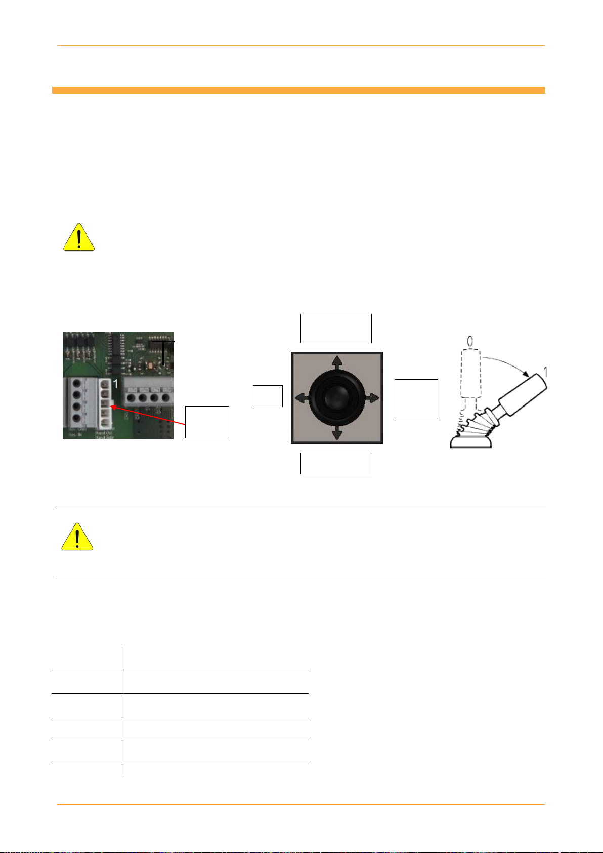
3.1 Joystick Functions
The external Joystick can be plugged into socket XJ1 during operation of the EK-S1 after removing the cover
of the housing. Automatic mode and manual mode from CTC is deactivated once the joystick is plugged in.
Only the system where the joystick is plugged in will move in the direction indicated by the joystick.
For example, the modules can all be set flat, for maintenance work (mowing grass), or at a steep incline, for
manual snow removal. The system will switch back to automatic mode once the joystick is removed.
______________________________________________________________________________________
WARNING!
High voltage present! Only qualified personnel may open the housing and connect the joystick.
______________________________________________________________________________________
CAUTION!
Serious damage to the tracker will happen when exceeding the maximum angle values.
Use an angle meter to not exceed the maximum physical angles of 700East and 500West.
3.2 Pin assignment
Terminal
designation
Function
XJ1 Pin 1
Moving to face west
XJ1 Pin 2
Moving to face east
XJ1 Pin 3
Moving to table “SAFE” position
XJ1 Pin 4
“ON” signal to CTC (+24 V)
XJ1 Pin 5
(+24V)
Horizontal
position
No function
East +
Snow
removal
West
Terminal
XJ1

27.06.2019 ASSEMBLY INSTRUCTIONS MLD CONTROL EK-S1 Page 13
4 Wind Guard
4.1 Wind guard
The wind alarm becomes activated when the wind speed continuously exceeds the default setting of 12 m/s.
The alarm will stop when the wind speed is continuously slower than the default setting of 10 m/s for a
duration of approximately 10 minutes. If the wind speed exceeds 10 m/s within these 10 minutes, the timer
will start over for another 10 minutes. The alarm can be cancelled earlier by clicking System Reset button in
CTC software Manual Control. Please see a detailed description in CTC software manual.
Speed [m/s]
12m/s
10m/s
1s 10 min
Zeit [ ]
Relay is deactivated
Relay is activeted
Wind alarm
Wind alarmstop
4.2 Assembly
_____________________________________________________________________________________
CAUTION!
The anemometer must be installed in a higher location where it is exposed to wind at all times.
The anemometer cannot be installed in the wind shadow of objects.
The minimum height must be at least the height of the top edge of the module surface when the
tracker is in complete east end position!
______________________________________________________________________________________
NOTE!
Anemometer assembly directly on the tracker is not allowed!!!
4.3 Connection
The anemometer is equipped with a 20 m connection cable. The cable has to be connected to the EK-S1 as
described in chapters 2.3 and 6.
____________________________________________________________________________________
NOTE!
An anemometer does not have to be installed on every DEGER system in a solar energy plant that
has several systems. One anemometer can be used for up to 100 EK-S1.
Terminal
designation
Function
XH1 Pin C
- DC 24 V
Wire 1 of anemometer
XH1 Pin D
- DC 0 V
Wire 2 of anemometer
XH1 Pin B
Signal input
- 0 to 20 mA
Wire 4 of anemometer
XH1 Pin A
- DC 24 V
Wire 5 of anemometer
Cable length 20 m
27.06.2019 ASSEMBLY INSTRUCTIONS MLD CONTROL EK-S1 Page 14
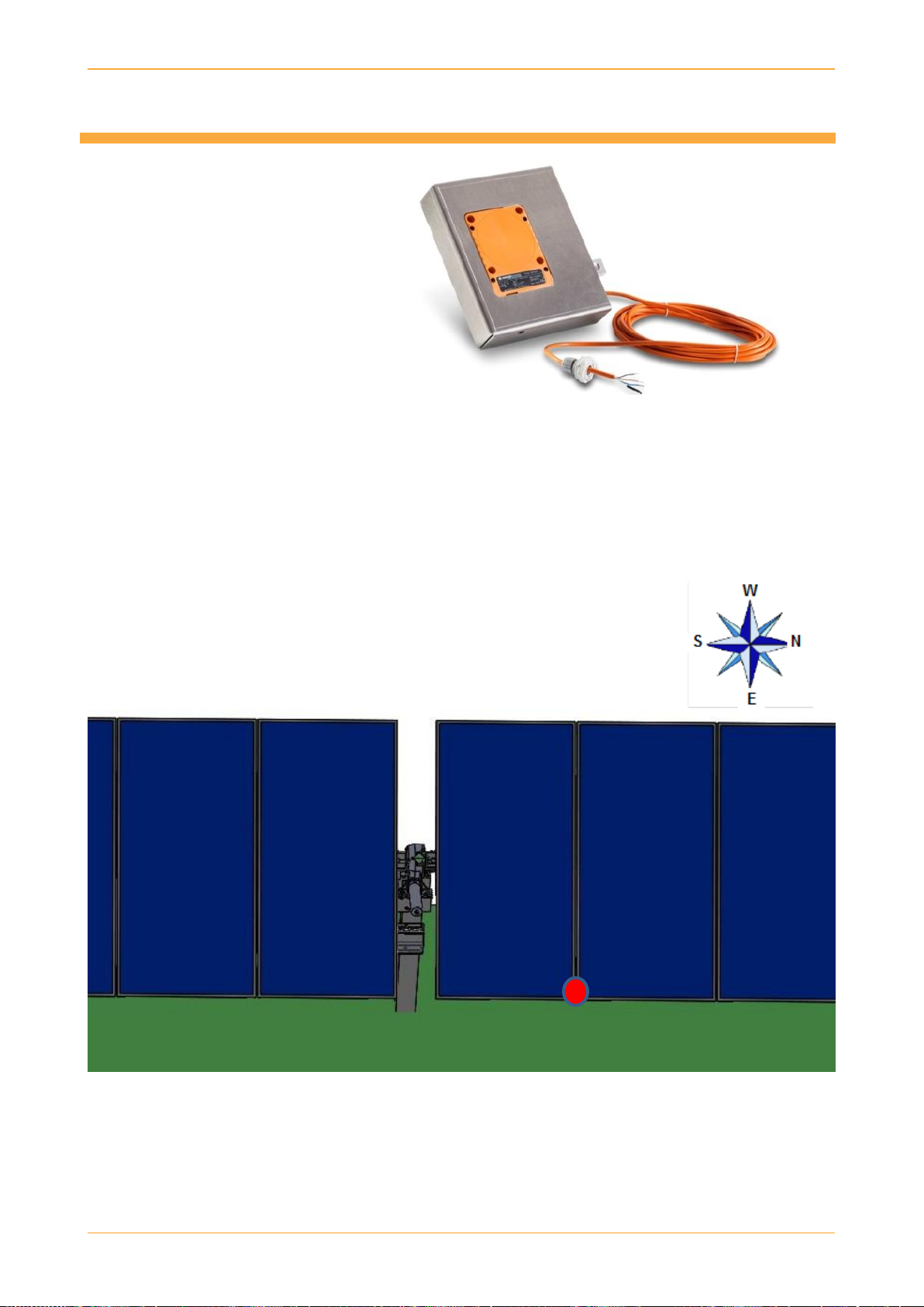
5 Snow Sensor
5.1 Function
The snow sensor detects
accumulations of snow and ice
on the DEGER system.
When a certain amount of snow
or ice accumulates on the
sensor, a signal is sent to the
CTC, which moves the solar
modules into the greatest
inclined position to facilitate the snow to slide off.
______________________________________________________________________________________
NOTE!
Do not change the default switching threshold on the snow sensor. Changing the default setting
will void any warranty claims.
______________________________________________________________________________________
5.2 Positioning
The snow sensor has to be mounted to the eastern side of the modules
positioned next to the middle of the tracker.
It is suitable for module heights up to 65 mm.
27.06.2019 ASSEMBLY INSTRUCTIONS MLD CONTROL EK-S1 Page 15
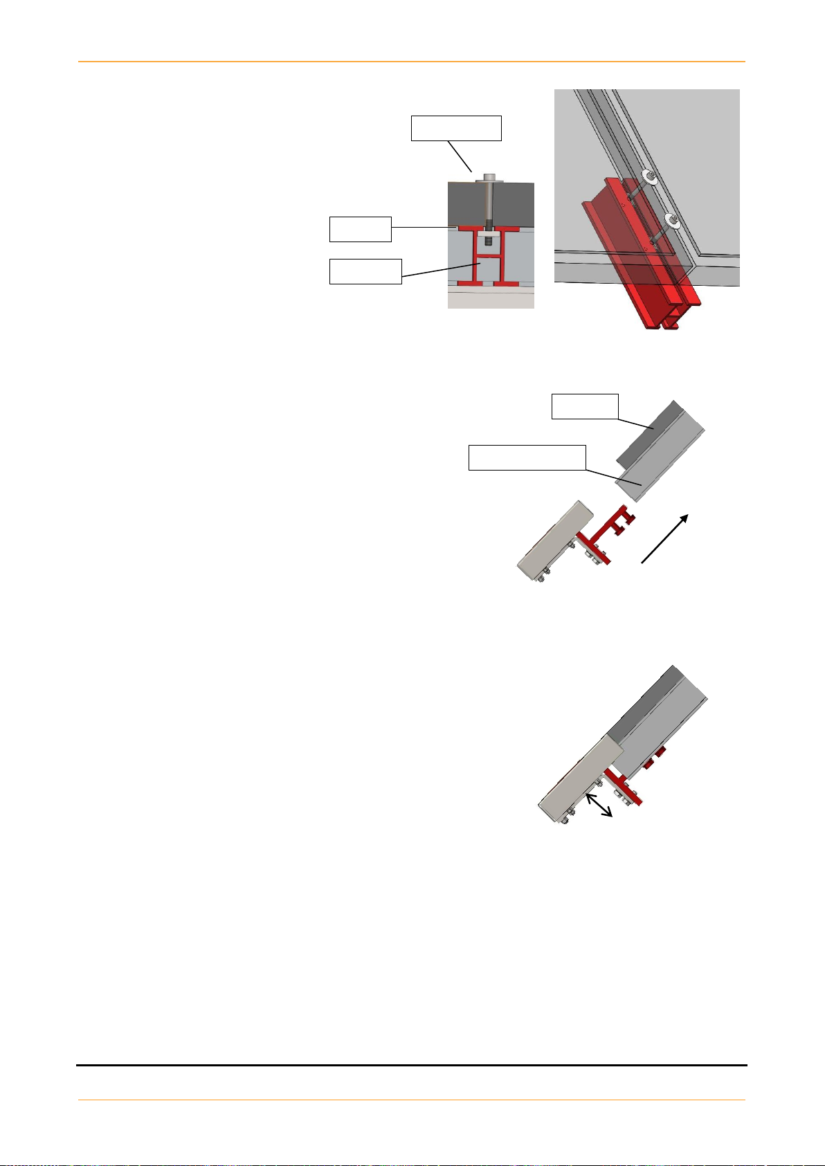
5.3 Assembly
1. The 20 cm aluminum profile has to be
mounted to the east side of the module
surface using two bolts M6, two clamp
plates and two sliding nuts M6.
Torque: 8 Nm
___________________________________________________________________________________
2. Loosen bolts M10x20 and slide the snow sensor into
the aluminium profile from underneath until it is flush
against the solar module.
Torque: 38 Nm
______________________________________________________________________________________
3. Position the snow sensor so that it is flush with the upper
edge of the module surface.
To do so, loosen the two bolts, M8x20, on the angle holder
and place the snow sensor at the height of the modules.
The snow sensor housing should not stick out above or sit below
the module surface.
Torque: 19 Nm
5.4 Connection
The snow sensor is equipped with a 5 m connection cable. The cable has to be connected to the EK-S1 as
described in chapters 2.3 and 6.
____________________________________________________________________________________
NOTE!
A snow sensor does not have to be installed on every DEGER system in a solar energy plant that
has several systems. One snow sensor can be used for up to 100 EK-S1.
Aluminum profile
Module
Module
Sliding nut
Clamp plate

27.06.2019 ASSEMBLY INSTRUCTIONS MLD CONTROL EK-S1 Page 16
6 Connections
6.1 Block diagram
______________________________________________________________________________________
DANGER!
Only trained and qualified personnel may connect the EK-S1 to external devices.
______________________________________________________________________________________
DANGER!
The external voltage supply must meet the regional regulations. The EK-S1 must have mandatory
disconnection ability from the supply voltage by a 6A-B circuit breaker. The circuit breaker must be
fully accessible.
______________________________________________________________________________________

27.06.2019 ASSEMBLY INSTRUCTIONS MLD CONTROL EK-S1 Page 17
6.2 CAN-Bus
6.2.1 CAN-Bus connections EK-S1
The EK-S1 offers two connections: CAN Bus In (terminal XK) and Can Bus Out (terminal XL).
The shielding of the CAN-Bus cables must be properly stripped and fixed into the metal clips X4 and X5.
The first EK-S1 in the Can-Bus chain (ID1) is connected to the PC running the CTC (Central Tracker Control)
software.
The last EK-S1 in the Can-Bus chain (IDn) is only connected to the terminal XK (CAN Bus In).
6.2.2 Connecting CAN-Bus to the management PC
For connecting the PC running the CTC you need a CAN-USB adapter from Lawicel. More information and
sources can be found on the website www.canusb.com.
The CAN-bus cable must be terminated with a 120 ohm resistor at the adapter end between CAN-High and
CAN-Low, i.e. pin 2 and pin 7 of the D-Sub 9 female plug, which is needed to connect the CAN-Bus cable to
the adapter.
The termination at the EK-S1’s is made onboard, so you don’t need a resistor at the last unit in the CAN-bus
chain.
For more information about CTC functionality and features refer to the “CTC User Guide”.

27.06.2019 ASSEMBLY INSTRUCTIONS MLD CONTROL EK-S1 Page 18
6.3 Uninterruptible power supply for a DEGER system
It is possible to provide an Uninterruptible Power Supply (UPS) for a DEGER system. The power provided will
move the DEGER system in case of a power failure into safety position.
The UPS must be dimensioned to deliver a power of 180 Watt for at least 10 minutes per EK-S1.
Furthermore the UPS has to be designed to be in accordance with local environment and the legal regulations.
The UPS must be wired as shown in the following connection diagrams. The potential free contact has to be
connected only to one EK-S1, the power failure information will be forwarded to other EK-S1 via CAN-Bus.
The system moves immediately after the failure of the supply voltage to storm position/safety position.
UPS with potential free contact:
UPS without potential free contact:

27.06.2019 ASSEMBLY INSTRUCTIONS MLD CONTROL EK-S1 Page 19
7 Start-up
DANGER!
Electrical current can be fatal!
Contact with live components can be fatal due to electric shock.
The external voltage supply must meet the regional regulations.
The EK-S1 must be able to be disconnected from the power supply by a 6A-B circuit breaker.
The circuit breaker must be fully accessible.
CAUTION!
Danger from unintentional movement of the machine!
Moving parts during DEGER system start-up can cause injury.
Do not remain within the DEGER’s system range of rotational motion.
Remove objects from the DEGER’s system’s range of rotational motion.
The EK-S1 is delivered with prewired MLD-sensor, Inclination sensor cabling and motor cabling.
PG glands for the CAN-Bus (M20) and AC power (M16) will be pre-installed.
Open the cover and connect the CAN-Bus cables as described in section 6.2.1.
If the respectice EK-S1 is determined for connecting the Wind sensor and/or the Snow sensor install the PG
glands and connect the cables to the designated terminals as described in section 2.2. and 2.3.
Connect the AC power IN- and OUT cables to the respective terminals described in section 2.3.
Close all housing covers. Torque 1.2 Nm (hand-tight)
Supply power to the EK-S1 and perform the Initial start-up check as described in chapter 10, check main
LED’s as described in section 2.4.1.

27.06.2019 ASSEMBLY INSTRUCTIONS MLD CONTROL EK-S1 Page 20
8 Clearance Check
CAUTION!
Serious damage to the tracker will happen when exceeding the maximum angle values or
when connecting the motor with wrong polarity to the EK-S1.
The rotary drive must be moved along the entire path to ensure that the DEGER system mechanism can
move freely and that all cables are long enough for the entire range of motion.
Cables must not be subject to mechanical stress.
The full rotation spectrum should be achieved.
There should not be any unusual noise.
8.1 CTC manual control
The easiest way to perform the clearance check is to use the MANUAL CONTROL function of the CTC
(central tracker control) management software. See CTC User Guide.
8.2 Joystick
The EK-S1 joystick, as described in chapter 3.1, can also be used.
8.3 Battery pack
Alternatively, the drive motor can be connected to a battery pack (12 V to 26 V). A change in polarity will
change the direction of the motor. Use an angle meter to not exceed the maximum physical angles of 700
East and 500West (equal to the CTC software values of 200and 1400 generated by the inclination sensors).
______________________________________________________________________________________
NOTE!
When several DEGER systems are installed, the clearance check must be performed for every
system individually. This ensures that any possible installation errors can be localised before
damage occurs.
Other manuals for MLD Control Energy Converter S1
1
This manual suits for next models
2
Table of contents
Popular Media Converter manuals by other brands


Avitech
Avitech Pacific C-SHS user manual

Danfoss
Danfoss FC 100 operating instructions

Omnitron Systems Technology
Omnitron Systems Technology iConverter 2GXM quick start guide

SoundTraxx
SoundTraxx Tsunami TSU-AT1000 Application note

Transition Networks
Transition Networks SGPOE10 1 Series user guide

ClearClick
ClearClick Video2Digital user manual