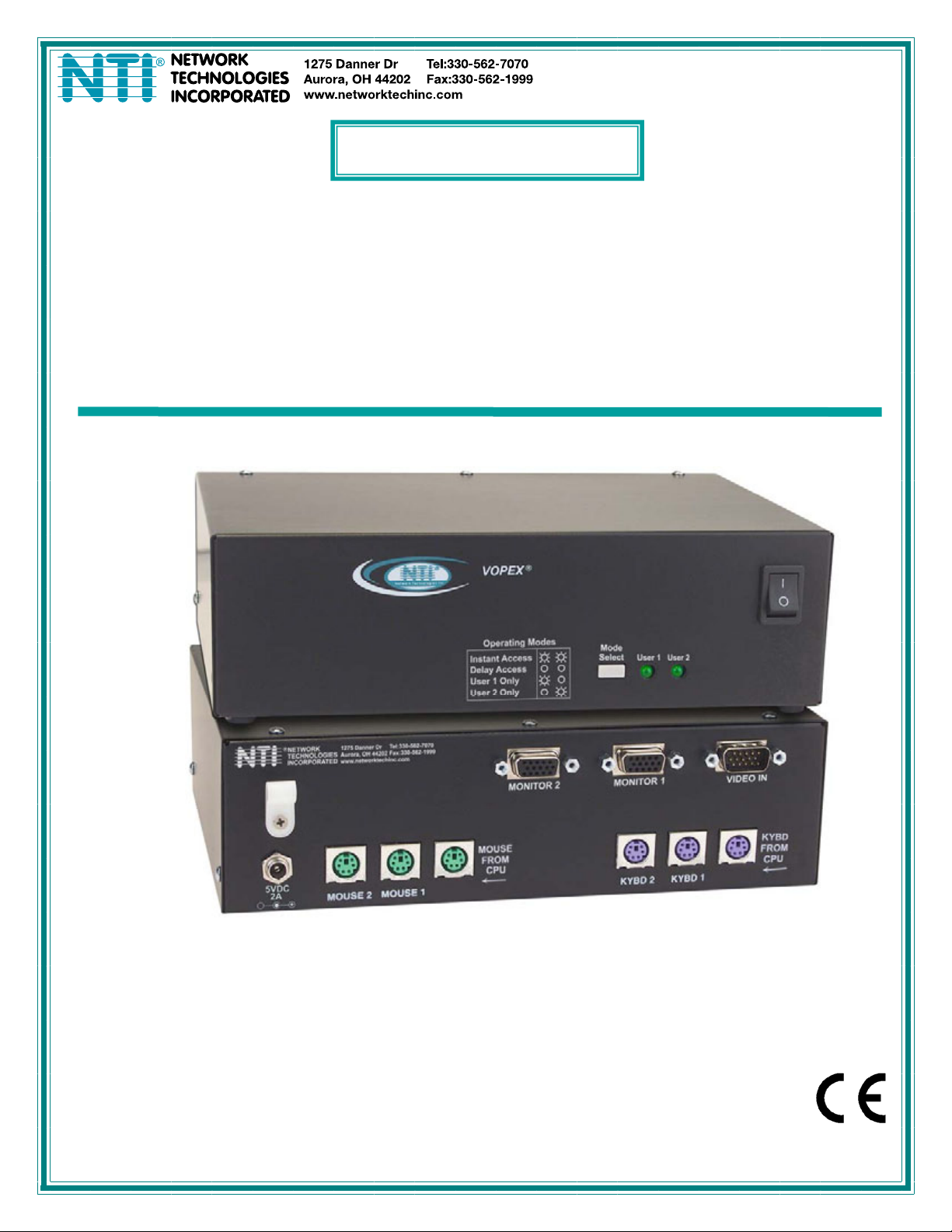
NTI VOPEX PS/2 KVM SPLITTER
1
INTRODUCTION
This VOPEX allows 1 IBM compatible CPU to support multiple users (either 2 or 4, depending on the VOPEX model). The PS/2
devices (keyboards and mice) of many different manufacturers can be plugged into the VOPEX when powering up. Also, any
combination of devices will work. (e.g. a mouse on port 2, keyboards on ports 3 and 4). Hot plugging devices at any time is fully
supported with the possible exceptions listed in “SPECIAL MOUSE CONSIDERATIONS” (page 3).
Features
•Multiple users can enter data from multiple locations
•Compatible with all PS/2 style PCs, RS6000, SGI, and HP9000
•Compatible with most PS/2 mice
•Keyboards and mice are hot-pluggable
•Interconnect NTI switches and splitters for complex applications
•Supports 1920 x 1200 resolution at 150MHz bandwidth
Option: VOPEX wtih stereo audio support- connect an audio source and up to 4 self-powered-stereo audio speakers-
Order VOPEX-4KVIMA-A (4-port) or VOPEX-2KVIMA-A (2-Port)
MATERIALS
Materials Supplied with this kit
•VOPEX 2/4KVIM-A 2 or 4 Port PS/2 KVM Splitter
•110 or 220VAC at 50 or 60Hz-5VDC/2A AC Adapter
•Line cord, country specific
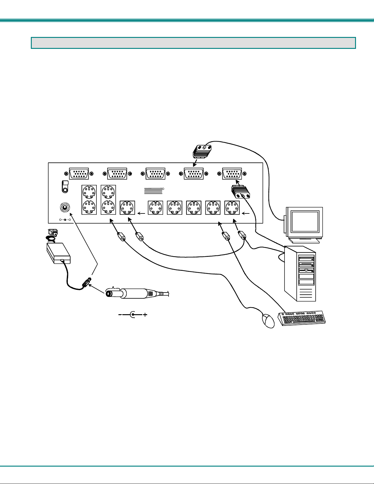
•A set of cables connecting the VOPEX to the IBM compatible CPU:
•VEXT-3 -Connects the Video port of the CPU to the VOPEX
•VVKINT-3-MM -Connects the PS/2 keyboard and mouse ports of the CPU to the
VOPEX
•SA-3-MM -Connects the Audio port of the CPU to the VOPEX (models with audio
support only)
Optional Materials
•A cable for each device to be connected to the VOPEX. The maximum length of these cables is 100 feet.
•VVKINT-xx -PS/2 Keyboard or Mouse extension cable (3, 6, 10, 15 and 25 foot lengths available)
•VVKEXT-xx -PS/2 Keyboard or Mouse extension cable (35, 50, 75, and 100 foot lengths available)
•VEXT-xx -VGA video extension cable (3,6,10,15,25,35,50,75 and 100 foot lengths available)
•SA-xx-MF - Audio Extension cable (3,6,12,14, 25, and 50 foot lengths available)
where: xx is the length of the cable in feet, and
MM indicates male-to-male connectors.
Cables can be purchased from Network Technologies Inc by calling (330) 562-7070, or (800) RGB-TECH (800-742-8324), or by
visiting our website at http://www.networktechinc.com.
Note: Any internal building wiring must be performed by a local licensed electrician and comply with the National
Electrical Code (NEC) requirements.