DEI PCX-7500 User manual

PCX-7500
Pulsed Current Source
Operation Manual
Directed Energy, Inc.
1609 Oakridge Dr., Suite 100, Fort Collins, CO 80525
(970) 493-1901
www.ixyscolorado.com

Contents
Contents........................................................................................................................................................2
Safety............................................................................................................................................................4
SafeOperatingArea......................................................................................................................................5
Introduction................................................................................................................................................12
Description......................................................................................................................................12
FrontPanelFeatures.......................................................................................................................13
RearPanelFeatures........................................................................................................................14
AccessoriesIncluded.......................................................................................................................16
InterfacingtheLoadtotheOutputCable...................................................................................................17
QuickStartGuide........................................................................................................................................19
Safety..............................................................................................................................................19
Requirements..................................................................................................................................19
ControllingthePCX‐7500fromtheFrontPanel.............................................................................19
ControllingthePCX‐7500fromaComputer...................................................................................20
Operation....................................................................................................................................................21
Setup...............................................................................................................................................21
PowerUp.........................................................................................................................................21
HomeHelpScreen..........................................................................................................................22
SettingtheOutputCurrent.............................................................................................................22
SettingtheTriggerSource...............................................................................................................22
SettingtheFrequency.....................................................................................................................23
SettingthePulseWidth..................................................................................................................23
SettingsMenu.................................................................................................................................24
ViewingInformationaboutthePCX‐7500......................................................................................24
ViewingtheCommunicationSettings.............................................................................................24
SavingtheSettings..........................................................................................................................27

RecallingtheSettings......................................................................................................................27
PowerDown....................................................................................................................................27
CommandSet..............................................................................................................................................28
WarrantyandService..................................................................................................................................33
Warranty.........................................................................................................................................33
FactoryServiceandSupport...........................................................................................................34

Safety
•Always refer to the safe operating section of the manual for your model of the
PCX-7500 system.
•Do not open the cover of the PCX-7500. There are no user-serviceable parts
inside. Opening the cover exposes you to shock and voids the factory warranty.
•Do not install, handle, or remove the output cables or laser diode while the PCX-
7500 is operating. Allow at least 10 minutes after powering down before
handling the output cable or laser diode.
•Do not use this device in a manner not specified by the manufacturer.
•Allow sufficient space around this device for air circulation. Cooling air enters the
rear of the chassis and exits the front of the chassis.
•Do not use where liquids are present or in corrosive environments. Clean this
instrument by wiping with a dry or damp cloth.
WARNING
Risk of lethal electric shock. Do not open the cabinet of this device. Do not touch
the output or laser diode while it is operating. This device produces LETHAL
levels of electric current, both inside its cabinet and at its output.
DO NOT OPERATE THIS DEVICE UNLESS ANOTHER PERSON, CAPABLE OF
RENDERING FIRST AID OR RESUSCITATION, IS PRESENT.
SAFE AND PROPER OPERATION OF THIS DEVICE IS THE RESPONSIBILITY OF
THE USER.
Directed Energy, Inc. (DEI) provides information on its products and associated
hazards, but it assumes no responsibility for the after-sale operation and safety
practices.

Safe Operating Area
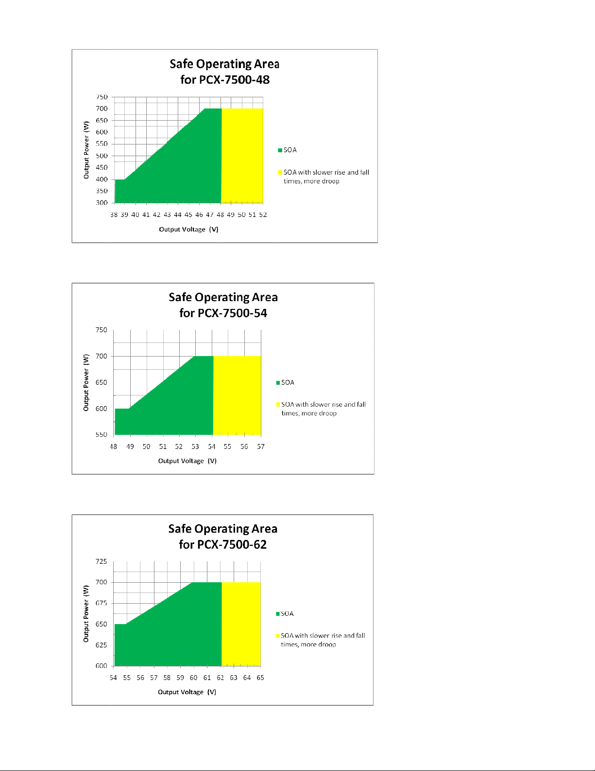
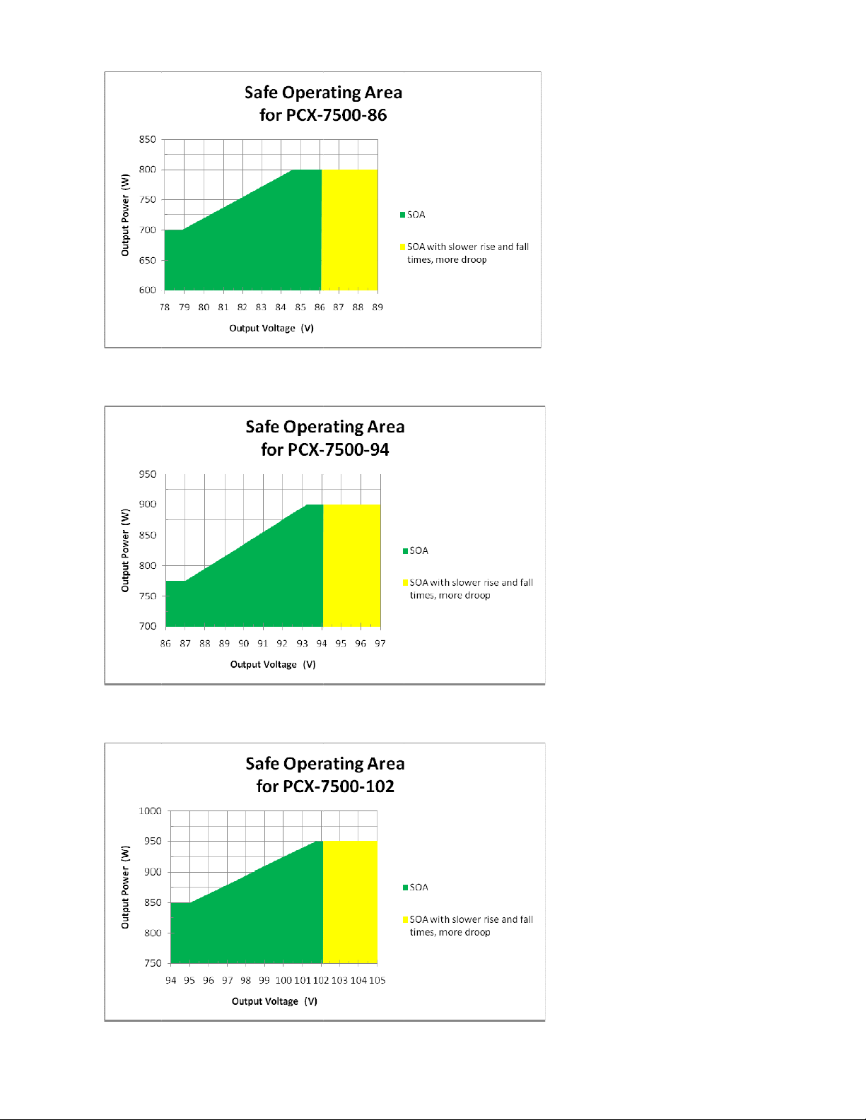
This section contains Safe Operating Area (SOA) graphs for all PCX-7500 models. In
each graph, the Safe Operating Area consists of the green and yellow shaded areas.
IMPORTANT: Do not operate the instrument outside of the Safe Operating Area!
Although the PCX-7500’s internal and external triggering system allow it to operate
outside the Safe Operating Area, such operation will result in permanent damage to the
PCX-7500, the laser diode, or both.
The green region represents operating parameters for which the instrument functions
safely and all pulse specifications are met. It is best to always operate in this region, but
operation in the yellow region does not cause damage to the instrument or laser.
The yellow region represents operating parameters for which the instrument functions
safely but pulse specifications may not be met. Operation in this area has not been
characterized by DEI, is not guaranteed by specification, and may vary slightly from
instrument to instrument. For example, rise and fall times may be slower and droop may
be greater than specified.
Here is an example of how to use the SOA graph to calculate maximum pulse width:
Assumethelaserisratedat5V200W,thepulserisaPCX‐7500‐5,andthedesiredpulseis400
Aat500Hz.
AccordingtothePCX‐7500‐5SOAgraph,at5Vthemaximumoutputpoweris100W.
Inthiscasetheinstrument(100W),notthediode(200W),isthelimitingfactor.Ifthediode
wasratedbelow100W,usethelaser’smaximumpowerandnottheSOAvalueinthenextstep.
Findthemaximumdutycycle:
power=voltage*current*duty_cycle
duty_cycle=100W(SOAgraph)/[5V(laserforwardvoltage)*400A]=0.050
Findtheperiod:
period=1/frequency=1/500Hz=0.002s
Findthemaximumpulsewidth:
maximumpulsewidth*=period*duty_cycle=0.002s*0.050=100µs
*Theabsolutemaximumpulsewidthshouldneverexceed5milliseconds,eveninsingleshot
operation.
Aslongasthepulsewidthis100usorless,theinstrumentwillberunningintheSOA.
Tocalculatethemaximumpulsewidthforasingle‐shotpulse(usingexternaltrigger),use1Hz
asthepulsefrequency.Remember,theoutputpulsewidthshouldneverexceed5milliseconds.


Introduction
Description
The PCX-7500 is an air-cooled, high-power current source designed to drive laser
diodes, bars, and arrays. The output current can be set from 10 A to 450 A; the
compliance voltage depends on the model. The pulse width is adjustable from 4
µs to 5,000 µs with a frequency range of 8 Hz to 10,000 Hz.
The PCX-7500 may be operated through its intuitive front panel controls. The color
QVGA LCD provides immediate visual confirmation of all operating parameters,
including pulsed current setpoints, internal trigger pulse width, internal trigger
frequency, and error/fault messages.
For automated applications, complete control of the instrument is provided through
RS-232, USB, and Ethernet computer interfaces. Up to four system configurations
may be stored in internal nonvolatile memory, providing instant recall of frequently-
used configurations.
The laser diode is connected to the PCX-7500 through a low-impedance stripline
cable designed to preserve the fidelity of high-speed current pulses. The output
connector is interlocked such that the PCX-7500 is disabled when the connector is
removed.
Conveniently-located front panel BNC connectors allow the PCX-7500 to be
externally triggered and synchronized for specialized interconnected equipment
applications. The impedance of the trigger input can be set to either 50 Ωor
10,000 Ω. The synchronization output pulse is synchronized to the leading edge of
the output current pulse and is active with an internal or external trigger. The delay
between the sync output signal and the main output current pulse is approximately
100 ns, measured from rising edge to rising edge.
The PCX-7500 has the ability to store four unique user settings, which include all
system configurations for operation of the PCX-7500.

Front Panel Features
Touch Screen
The touch screen provides a graphical user interface and touch control to adjust all
functions of the PCX-7500.
Encoder Knob
Turn the encoder knob to change a value for functions of the PCX-7500. Push it to
cycle through the resolutions (increments of value change).
Local Button Mode
Pressing the LOCAL button returns the PCX-7500 to front panel control from
computer control. The LOCAL button is lit when the computer is in control.
Enable Button Mode
The ENABLE button selects whether the PCX-7500 output current is enabled or
disabled. The ENABLE button is lit when the unit is enabled. The unit can only be
enabled when the key switch is in the ON position.
Current Monitor (IMon)
This BNC connector provides a connection to an oscilloscope. The signal is a
voltage representation of the output current at the output current connector, and
ranges from 0 V to 1.5 V. At 100 A output current there will be approximately 330
mV on the IMon connector.
External Trigger
This BNC connector accepts trigger pulses from an external source. Its input
impedance can be set to either 50 Ωor 10,000 Ω.
LocalButton
EnableButton
TouchScreenEncoderKnob
CurrentMonitor
ExternalTrigger
Sync
Ke
y
switch

Sync Output
Synchronization pulses for external devices are available at the Sync Output BNC
connector. The sync pulse corresponds to the leading edge of the output current
pulse.
Keyswitch
The keyswitch ON position allows the PCX-7500 output current to be enabled. In
the keyswitch OFF position, the PCX-7500 is disabled.
Rear Panel Features
Current Output
This socket accepts the factory-supplied output cable and is the connection for the
system-generated current pulses. DO NOT TOUCH any part of this cable while the
PCX-7500 is powered up. Please review the Safety section.
Note: The absence of a properly installed output cable disables the output and
creates an output enable fault.
Rear Enable
This connector accepts either an external dry contact closure or the factory-supplied
shorting BNC plug. Closed contacts or the use of the shorting plug enables the
output. Open contacts or removal of the shorting plug disables the output and
creates a rear enable fault.
USB
Ethernet
RS232
ACPowerConnector
CurrentOutput
PowerSwitch
RearEnable
VoltageMonitor

Voltage Monitor (VMon)
This BNC connector allows the user to monitor the voltage on the output cable. The
VMon voltage voltage is linearly scaled to the output connector voltage and ranges
from 0 V (0 V on the output connector) to approximately 1.392 V (120 V on the
output connector).
USB Connector
Use this connector to communicate with an external computer with a USB cable.
Ethernet Connector
Use this connector to communicate with an external computer through an Ethernet
network.
RS232 Connector
Use this connector to communicate with an external computer via a RS-232 cable.
Power Cord Connector
The power cord connector accepts type IEC 320 C-19 to NEMA 5-20P grounding
equipment power cord.
On-Off Power Switch
This switches powers the PCX-7500 on and off.

Accessories Included
AC Power Cord
Factory-supplied power cord, type IEC 320 C-19 to NEMA 5-20P grounding
equipment power cord.
Output Stripline Cable
This factory-supplied cable provides output current pulses to external
devices. A DB-37 male connector fits the socket on the rear panel of the
PCX-7500; a DB-37 female connector is on the user end.
Shorting BNC Plug
The shorting BNC plug attaches to the Rear Enable BNC connector on the rear
panel. It takes the place of closed contacts and enables the output.
Keyswitch Keys
The keys access the front panel on-off keyswitch. The output is enabled when the
keyswitch is in the ON position.
ACPowerCord
OutputStripline
Cable
KeyswitchKeysRearEnableBNC
Connector

Interfacing Load to the Output Cable
The output of the PCX-7500 uses a DB-37 connector that is connected to a stripline
cable. One of these output cables is included with every system. The user may order
additional output cables if there is a need for more than one cable.
To interface to your load, you may solder the stripline directly to your load, or design a
simple two-layer interface board (recommended). The interface board must have very
low resistance, and more importantly, very low inductance in order to ensure that the
droop and overshoot specifications are met. In order to reduce the inductance, there
should be very wide copper planes on the top and bottom of the board and no copper
inner planes. PCBs thinner than 0.070 inches perform best in reducing inductance.
Copper thickness should be 2 ounces or more to reduce resistance.
DEI recommends soldering your laser directly to the interface PCB without any
additional cables or wire. If wires are absolutely necessary, they should be as short as
possible and twisted if longer than 3 cm. Wires and cabling from an interface board to
the laser will increase inductance which increases overshoot. DEI can design a custom
interface board for you at a nominal cost; please contact customer support for a
quotation.
The two photos on the next page show an interface board created for a laser used in
the DEI lab. The top of the interface board has solid copper from the stripline to the
laser’s positive terminal. The bottom of the interface board has solid copper plane
everywhere the positive plane is, plus additional copper to connect to the negative side
of the laser. The bottom copper is connected to the top of the board using as many vias
as possible (over 400 in this case). Using multiple vias reduces both inductance and
resistance. The laser is mounted in the center of the PCB, but it may be mounted
anywhere on the board.

TOP BOTTOM
Why are we trying so hard to reduce resistance?
Resistance in the output path turns electrical energy into unnecessary heat.
Designers spend a lot time and effort removing as much heat as possible from
their systems, thus resistance is an unwanted parameter.
Why are we trying so hard to reduce inductance?
Inductance in the output path can cause voltage overshoot on the rising and falling
edges of the output pulse. The overshoot voltage is defined by the following
fundamental equation:
V = L * di / dt
Assume we wish to generate a 450 A pulse with a 1 µs rise time and a voltage
overshoot of less than 10 volts. What is the maximum allowable inductance in the
output path?
L = V / (di/dt) = 10 V / (450 A / 0.000001 s) = 22 nH
It is easily seen that with high currents and fast rise times, voltages can increase
rapidly if inductance is not kept as low as possible. While we are more concerned
about current overshoot than voltage overshoot, the overall result is that the
current pulse can be affected by undesirable inductance in the output path.

Quick Start Guide
Safety
Follow the safety guidelines. DO NOT PROCEED WITHOUT UNDERSTANDING
AND OBSERVING THESE GUIDELINES.
Requirements
Make sure the PCX-7500:
•Is connected with the proper cables and termination impedance
•Is powered up
•Has all faults cleared
•Has the rear enable and keyswitch enabled (the proper icons will be green
when enabled)
Controlling the PCX-7500 from the front panel
1. Disable the PCX-7500
¾The Enable button on the front panel glows green if the PCX-7500 is
enabled. Press the button to disable. The green light goes out.
2. Set the output current
¾Press the Output button on the touch screen.
¾Press the encoder knob to set the resolution to x0.1, x1.0, or x10.0.
¾Turn the encoder knob to set the output current from 10.0 A to 450.0 A.
¾Press the Done button.
3. Set the trigger to internal or external
¾Press the Trigger button on the touch screen.
¾Press the Internal or External button to select the trigger.
4. Set the internal pulse trigger frequency
¾Press the Frequency icon on the touch screen.
¾Press the encoder knob to set the resolution to x1, x10, x100, x500,
x1000, or x5000.
¾Turn the encoder knob to set the frequency from 8 Hz to 10,000 Hz.
¾Press the Done icon.

5. Set the pulse width
¾Press the Pulse Width icon on the touch screen.
¾Press the encoder knob to set the resolution.
¾Turn the encoder knob to set the pulse width from 4 µs to 5 ms.
¾Press the Done icon.
6. Enable the PCX-7500
¾Press the Enable button on the front panel. The button lights green.
Controlling the PCX-7500 from a computer
1. Disable the PCX-7500
¾Send the command “OUTPUT:DISABLE”.
2. Set the trigger to internal or external
¾Send the command “TRIG:INTERNAL” or “TRIG:EXTERNAL”.
3. Set the internal pulse trigger frequency
¾Send the command “TRIG:INT:FREQ n”, where n = [8 to 10000].
¾Units are hertz.
4. Set the pulse width
¾Send the command “TRIG:INT:PULSEWIDTH nnnn”, where n = [4000 to
5000000]. Pulse width is dependent on the frequency.
¾Units are nanoseconds.
5. Set the output current
¾Send the command “SETPOINT:CURRENT n”, where n = [10 to 450.0].
¾Units are amperes.
6. Enable the PCX-7500
¾Send the command “OUTPUT:ENABLE”.
PulseWidth Frequency
32µsbetween8Hzto30Hz
8µsbetween 31Hzto122Hz
2µs 123Hzto500Hz
0.5µs 500Hzto10000Hz
This manual suits for next models
16
Table of contents
Other DEI Pulse Generator manuals
Popular Pulse Generator manuals by other brands

AVTECH ELECTROSYSTEMS LTD.
AVTECH ELECTROSYSTEMS LTD. AVR-3HE-B instructions

Agilent Technologies
Agilent Technologies N6030A Series user guide

Tektronix
Tektronix PG 508 instruction manual

Avtech
Avtech AVR-AHF-1-B series instructions

Princeton Instruments
Princeton Instruments Roper Scientific PG-200 manual

BNC
BNC MOD745T manual

HP
HP 8082a Operating and service manual

Hantek
Hantek HDG6000B Series user manual

Quantum Composers
Quantum Composers 9730 Series operating manual

Tektronix
Tektronix PG 507 instruction manual

HP
HP 8112A Operating, programming and servicing manual

Quantum Composers
Quantum Composers 9530 Series operating manual