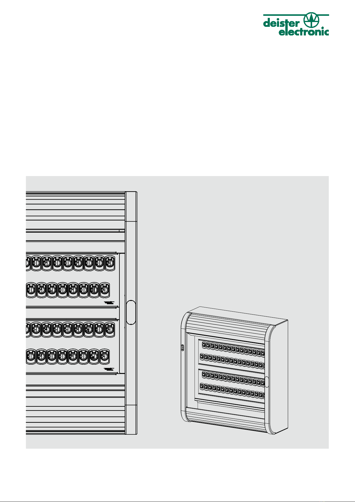
maxx-6u_manual_en_896453_v230131
Regulatory notices
Hereby, deister electronic declares that the device type maxx 6U is in compliance with directive 2014/30/EU.
The full text of the EU declaration of conformity is available at the following internet address:
http://go.deister.com/ce
Approved for use in all European countries.
Disclaimer
All rights reserved. No part of this publication may be reproduced, stored in a retrieval system, or transmit-
ted, in any form or by any means, electronic, mechanical, photocopying, recording, or otherwise, without
prior written permission of deister electronic GmbH.
deister electronic GmbH reserves the right to make changes to any and all parts of this documentation with-
out obligation to notify any person or entity of such changes.
deister electronic GmbH is not able to supervise the observance of the instructions given in this manual as
well as the conditions and methods used during installation, operation, and maintenance of the devices.
Therefore, we disclaim liability and reject responsibility for any losses, damages or costs that are caused by
misapplication, installation, handling errors or faulty operation or related to the above in any other way.
deister electronic GmbH
Hermann-Bahlsen Str. 11
30890 Barsinghausen
Germany
Phone: +49 (0) 51 05 - 51 61 11
Fax: +49 (0) 51 05 - 51 62 17
Web: www.deister.com
These instructions are available as a video at: https://dashboard.deister.com.
Log in with your access data. Alternatively, scan the QR code to go to the website: