DEK 3850 User manual

Rev: Sept 2009 DEK® is exclusively distributed by GXi International, LLC
1 of 14
Heavy Duty Power Equipment
Owner’s Manual
This manual contains important safety instructions for gasoline engine
powered electric generator models: 3850, 4000, 4550 Pro, 5000, 5000EL, 5650, 5650EL, 6500, 6500EL,
7550EL Pro, 180W, 180WEL.
READ SAFETY WARNINGS AND OPERATING INSTRUCTIONS CAREFULLY, SAVE THESE INSTRUCTIONS.
Contents:
1. Tools and Accessories
2. Warnings & Specifications
3. Component Identification
4. Wheel Kit Assembly
5. Controls
6. Operating the Generator
7. Maintenance
8. Transporting and Storage
9. Troubleshooting
10. Warranty and Service
HAVE QUESTIONS OR NEED HELP?
call 24 hrs / 7-days a week help-line: [1] 800-393-0668
or go to www.DEKPowerUSA.com
DO NOT RETURN THIS GENERATOR
TO THE STORE!
Date of Purchase: _______________________
Location of Purchase: _______________________
Serial #: _______________________
Have the following information ready when you call us:
DEK® is registered trademark of GXi International, LLC Clayton, NC 27520 USA
No part of this publication can be printed or copied without written permission.
®

Rev: Sept 2009 DEK® is exclusively distributed by GXi International, LLC
2 of 14
3850, 4000, 4550 Pro, 5000(EL), 5650(EL),
6500(EL), 7500EL, 180W(EL)
Heavy Duty Power Equipment Tools and Accessories
Required tools to assemble this generator:
1. An adjustable wrench or a wrench with an 8mm socket.
Additional equipment required to safely operate this
generator:
1. Gas can.
2. Unleaded gasoline.
3. SAE 10W30 motor oil (a little more than 1 quart for DEK
11hp and 13hp engines, a little less than 1 quart is re-
quired for DEK‟s smaller engines).
4. An oil fill funnel.
5. Gasoline fuel stabilizer (for storing your generator).
6. 120V and/or 240V extension cords.
7. An adjustable wrench or a 12mm socket for oil changes.
For your convenience, DEK of-
fers a complete range of gen-
erator accessories. Please ask
your local retailer for more de-
tails or call 1-866-550-3221.
Adapters:
Converts 240V twist lock
(L14-30) to six (6) 120V
outlets. Lighted ends
show when power is on.
Ideal for use in combina-
tion with a 240V extension
cord. Can handle up to 30
Amps (7500 Watts).
Extension Cords:
240V, 10/4, heavy duty
extension cords with L14-
30 connectors at each
end. Lighted end shows
when power is on. Ideal
for use in combination
with the 240V to 120V
adapter, eliminating up
to six 120V extension
cords. This cord re-
duces harmful voltage
drops experienced when
using most 120V exten-
sion cords. Available in
25‟ lengths and can be
combined to reach the
desired length.
Universal Generator Cover:
Heavy duty nylon cover fits over
most models of 4000W to 7500W
generators. A flexible handle bar
flap accommodates most com-
mon handle bar designs. The
cover keeps water, ice, snow,
dust and dirt from damaging your
generator when it is in storage. It
can also be used as a rain cover
to protect the generator when
stored outdoors. The cover can-
not be used while the generator
is in operation. The generator
should be allowed to cool down
for approximately 15 minutes
after being shut down, prior to
placing the cover over the gen-
erator.
SAE 10W30 Motor Oil:
A premium high performance
formulation designed for high
RPM small gasoline engines
such as those used on genera-
tors. This oil provides excel-
lent protection against viscosity
and thermal breakdown that
often happens under the pro-
longed severe duty experi-
enced by generator engines.
This oil is approved by the
engine manufacturer and
meets all the requirements and
specifications to remain in
compliance with the terms and
conditions of DEK‟s generator
warranty. Use of this oil formu-
lation is highly encouraged by
the manufacturer. Frequent oil
changes with high quality mo-
tor oil will prolong the life of
your DEK generator.
Fuel Stabilizer:
Use of DEK‟s fuel stabilizer
keeps your gasoline fresh for
up to 12 months. Gasoline
breaks down in 60 days, po-
tentially causing damage to
your engine. DEK recom-
mends storing your generator
with the fuel tank full and with
fuel stabilizer added. This
protects the engine and fuel
system from the effects of hu-
midity and ensures your gen-
erator is ready for use at all
times.

Rev: Sept 2009 DEK® is exclusively distributed by GXi International, LLC
3 of 14
Heavy Duty Power Equipment
This owner‟s manual is considered a permanent part of the gen-
erator and should remain with the generator if resold. The infor-
mation and specifications included in this publication were in
effect at the time of approval for printing.
GXi International, LLC, exclusive marketer of DEK Heavy Duty
Power Equipment, reserves the right to discontinue or change
specifications or design at any time without notice and without
incurring any obligation whatever. No part of this publication
may be reproduced without written permission.
The engine exhaust from this product contains chemicals
known to the State of California to cause cancer, birth de-
fects or other reproductive harm.
SAFETY LABEL LOCATIONS
These labels warn you of potential hazards that can cause seri-
ous injury. Read them carefully. If a label comes off or becomes
hard to read, contact your DEK generator dealer for a replace-
ment.
SAFETY INFORMATION
DEK generators are designed to give safe and dependable ser-
vice if operated according to instructions. Read and understand
this owner‟s manual before operating your generator.
OPERATOR RESPONSIBILITY
Know how to stop the generator quickly in case of emergency.
Understand the use of all generator controls, output receptacles,
and connections. Be sure that anyone who operates the genera-
tor receives proper instruction. Do not let children operate the
generator without parental supervision.
Fire and Burn Hazards
The exhaust system gets hot enough to ignite some materials.
Keep the generator at least 3 feet (1 meter) away from
buildings and other equipment during operation.
Do not enclose the generator in any structure.
Do not smoke when refueling.
Keep flammable materials away from the generator.
The muffler becomes very hot during operation and remains
hot for a while after stopping the engine. Be careful not to
touch the muffler while it is hot.
Let the engine cool before storing the generator indoors.
Refuel in a well ventilated area with the engine stopped.
Fuel vapors are extremely flammable and may ignite after
the engine has started. Make sure that any spilled fuel has
been wiped up before starting the generator.
EMISSION CONTROL SYSTEM INFORMATION
The U.S. and California Clean Air Acts
EPA and California regulations require all manufacturers to fur-
nish written instructions describing the operation and mainte-
nance of emission control systems. The following instructions
and procedures must be followed in order to keep the emissions
from your DEK engine within the emission standards. Mainte-
nance, replacement, or repair of the emission control devices
and systems may be performed by any engine repair establish-
ment or individual, using parts that are „„certified‟‟ to EPA stan-
dards.
WARNING
Connections to a Building Electrical System
Connections for standby power to a building electrical system
must be made by a qualified electrician. The connection must
isolate the generator power from utility power, and must comply
with all applicable laws and electrical codes. A transfer switch,
which isolates generator power from utility power, is available
through any of GXi‟s authorized dealers of DEK generators.
Improper connections to a building electrical system can
allow electrical current from the generator to backfeed into
the utility lines. Such backfeed may electrocute utility com-
pany workers or others who contact the lines during a power
outage, and the generator may explode, burn, or cause fires
when utility power is restored. Consult the utility company
or a qualified electrician.
Ground System
DEK portable generators have a system ground that connects
generator frame components to the ground terminals in the AC
output receptacles. The system ground is not connected to the
AC neutral wire. If the generator is tested by a receptacle tester, it
will show the same ground circuit condition as for a home recep-
tacle.
Special Requirements
There may be Federal or State Occupational Safety and Health
Administration (OSHA) regulations, local codes, or ordinances
that apply to the intended use of the generator. Please consult a
qualified electrician, electrical inspector, or the local agency hav-
ing jurisdiction.
This generator does not meet US Coast Guard regulation 33
CFR-183 and should not be used on marine applications.
CARBON MONOXIDE GAS
Exhaust contains poisonous carbon monoxide, a colorless
and odorless gas. Breathing exhaust can cause loss of con-
sciousness and may lead to death. To keep exhaust gas
from accumulating, use in an area with adequate ventila-
tion. DO NOT use this generator in a garage, basement,
crawlspace, enclosed shed, or any other area that does not
have adequate ventilation. DO NOT use this generator near
ventilation ducts or open windows that may allow exhaust
gasses to enter your home or business. ONLY operate this
generator outdoors.
WARNING
WARNING
Electric Shock Hazards
Keep the generator dry.
DO NOT use the generator in wet conditions, rain or
snow, or near a pool or sprinkler system
DO NOT use when your hands are wet
NEVER START OR STOP THE ENGINE WITH DEVICES CON-
NECTED TO THE GENERATOR.
WARNING
WARNING
WARNINGS 3850, 4000, 4550 Pro, 5000(EL), 5650(EL),
6500(EL), 7500EL, 180W(EL)

Rev: Sept 2009 DEK® is exclusively distributed by GXi International, LLC
4 of 14
WARNINGS
Failure to properly follow main-
tenance instructions and precautions can cause serious
injuries or death. Always follow the inspection and mainte-
nance recommendations and schedules in this owner’s
manual.
Safety Precautions:
Make sure the engine is off before you begin any maintenance
or repairs. This will eliminate several potential hazards:
Carbon monoxide poisoning from engine exhaust.
Be sure there is adequate ventilation whenever you
operate the engine.
Burns from hot parts.
Let the engine and exhaust system cool before touch-
ing.
Injury from moving parts.
Do not run the engine unless instructed to do so.
In the State of California a spark arrestor is required by law.
Other states may have similar laws. Federal laws apply on all
federal lands. If you equip the muffler with a spark arrestor, it
must be maintained in effective working order. See page 11.
Rapid retraction of the recoil starter cord can pull the
starter cord back faster than you can let go. When starting
the engine, pull the cord slowly until resistance is felt then
pull rapidly to avoid kickback.
WARNING
WARNING
AC Applications
Before connecting an appliance or power cord to the generator:
1. Make sure that appliances are in good working order.
Faulty appliances or power cords can create a potential for
electrical shock. If an appliance begins to operate abnor-
mally, becomes sluggish or stops suddenly, turn it off imme-
diately.
2. Disconnect the appliance, and determine whether the prob-
lem is the appliance, or if the rated load capacity of the gen-
erator has been exceeded.
3. Make sure that the electrical rating of the tool or appliance
does not exceed that of the generator. Never exceed the
maximum power rating of the generator. Power levels be-
tween rated and maximum may be used for no more than
30 minutes.
Substantial overloading will open the circuit breaker. Ex-
ceeding the time limit for maximum power operation or
slightly overloading the generator may not switch the
circuit breaker or circuit protector OFF, but will shorten the
service life of the generator.
Limit operation requiring maximum power to 30 minutes. For
continuous operation (longer than 30 minutes), do not exceed
the rated power.
The total power requirements (VA) of all appliances connected
must be considered. Appliance and power tool manufacturers
usually list rating information near the model number or serial
number.
Changing the speed of the generator by adjusting the governor can cause damage to the gen-
erator, devices attached to the generator, and may result in bodily injury. Do not adjust or
tamper with the engine speed setting.
Heavy Duty Power Equipment
Product Specifications
3850, 4000, 4550 Pro, 5000(EL), 5650(EL),
6500(EL), 7500EL, 180W(EL)
Generator 3850, 4000 4550 Pro 5650/5650EL
6500, 6500EL 7550EL Pro 180W, 180WEL
Rated frequency 60 Hz 60 Hz 60 Hz 60 Hz 60 Hz 60 Hz
Rated voltage 120V / 240V / 12V 120V / 240V / 12V 120V / 240V / 12V 120V / 240V / 12V 120V / 240V / 12V 120V / 240V / 12V
Rated output power 4 kW (Max.) 4.55 kW (Max.) 5.6 kW (Max.) 6.5 kW (Max.) 7.55 kW (Max) 6.0 kW (Max.)
AC output (Max.) 16A 18.95A 23.5A 27.1A 31.5A 18A
DC output 12V, 8.3A 12V, 8.3A 12V, 8.3A 12V, 8.3A 12V, 8.3A
36V, 200A welder and
12V, 8.3A output
Engine type OHV 4-Stroke OHV 4-Stroke OHV 4-Stroke OHV 4-Stroke OHV 4-Stroke OHV 4-Stroke
displacement 270 cc 270 cc 390 cc 390 cc 401cc 390 cc
Compression ratio 8.2:1 8.2:1 8.0:1 8.0:1 8.0:1 8.0:1
Rated rotation speed 3600 RPM 3600 RPM 3600 RPM 3600 RPM 3600 RPM 3600 RPM
Rated power 8.8 Hp 10 Hp 11 Hp 13 Hp 14 Hp 13 Hp
Starting system Recoil Recoil Recoil and electric starter Recoil and electric starter Electric starter
Recoil and optional
electric starter
Rotation direction Counter clockwise Counter clockwise Counter clockwise Counter clockwise Counter clockwise Counter clockwise
Fuel type Unleaded gasoline Unleaded gasoline Unleaded gasoline Unleaded gasoline Unleaded gasoline Unleaded gasoline
Low oil alert Yes Yes Yes Yes Yes Yes
Fuel tank size 5.94 gallons 12.6 gallons 5.94 gallons 5.94 gallons 12.6 gallons 5.94 gallons
Integrated voltmeter Optional feature Yes Yes Yes Yes Yes
Models

Rev: Sept 2009 DEK® is exclusively distributed by GXi International, LLC
5 of 14
Fuel Tank Fuel Cap
Fuel Valve
Oil Fill Cap and Dipstick
ON/OFF Switch Digital Meter
Battery (electric start option only)
Start Switch (electric start option only)
L14-30 240V/120V Twist Lock Connector
12V DC terminals
Recoil Starter
Air Filter
Choke Lever
Ground Lug
Data Tag
Fuel Gauge
Engine Serial Number
Choke Lever
Valve Cover
Muffler GuardFrame Ground Lug
Alternator
Exhaust Pipe
Generator models may
have different features and/
or options than shown in
these diagrams. DEK re-
serves the right to alter
product features and
specifications.
Component Identification
Heavy Duty Power Equipment
Oil Drain (on both sides)
Push Button Breakers (for each outlet)
Emissions Information
Handle Bars
(recessed)
A+B
240V AC
NEMA L14-30
A Outlet s- 120V AC
Pr ess to r eset cir cui t break ers.
Pr esione par a reesta blec er el in ter rupt or de cir c uit os.
12V DC
On
Off
Shows hours o f use, runnin g volta ge,
and fre quency.
Muestra las ho ras de uso, el v oltaje
corrient e y la fr ecuencia .
Digital Meter
Turn to
Start
B Outlets - 120V AC
Pr ess to r eset cir cui t break ers.
P r e s i o n e p a r a r e e s t a bl e c e r el i n t e r r u p t o r d e
ci r c u i t o s .
FIL L ENGINE WIT H OIL B EFO RE
STARTIN G. Wh e n th e o il l ev el is l o w,
th e e ng i ne a ut om a ti c ally stop s
run n i ng.
DO N OT O PER AT E IN DO ORS.
DO N OT O PER ATE WH EN WET .
READ T HE O WNE R‟S M ANU AL
BEFOR E STA RTI NG
LL ENE EL M OT OR C ON A CEITE
ANTES D E EN CEN DER. El m oto r s e
ap a ga au tom át ic am en te c u an d oe s tá
ba j o e l ni v e ld e a c ei te .
NO P ON GA E N FUN CIO NAMIENT O
EN INTE RIOR ES.
NO P ON GA E N FUN CIO NAMIENT O
CUAN DO ESTÉ M OJA DO.
LEA EL MANUAL D EL
PROPI ETARI O ANT ES DE
ENCE NDE R.
Engine
Pr ess to r eset cir cui t break ers.
Pr esione par a reesta blec er el
interr upt or de circuit os.
120V AC Outlets
3850, 4000, 4550 Pro, 5000(EL), 5650(EL),
6500(EL), 7500EL, 180W(EL)

Rev: Sept 2009 DEK® is exclusively distributed by GXi International, LLC
6 of 14
Required Tools (not supplied)
1. Adjustable wrench or a
socket wrench with a 8 mm
socket.
Approximate assembly time is
5 minutes.
Supplied with your generator:
1. Two(2) foot assemblies with
two (2) 8 mm nuts.
2. Two (2) wheel axle assem-
blies.
Heavy Duty Power Equipment Wheel Kit Assembly
Commissioning the Battery
WARNING
Lead acid storage batteries contain sulfuric acid which
can cause serious injuries. The battery also gives off
explosive gases. Keep sparks, flames and cigarettes
away. Provide adequate ventilation when charging or
using batteries. Battery posts, terminals and related
accessories contain lead and lead compounds. Avoid
spills of electrolyte and wash hands thoroughly after
handling.
Use gloves and safety glasses when handling and in-
stalling lead acid batteries.
If you get electrolyte in your eyes, flush your eyes with
clean water for 15 minutes and seek medical attention.
Keep out of reach of children.
Battery Maintenance:
Routine maintenance is essential to keep the battery in good
condition and maximize its service life.
1. Keep the terminals and connections free from corrosion
and coat with petroleum jelly or grease to reduce corrosion
from occurring.
2. If the generator sits idle for more than two (2) months, it is
best to recharge the battery to ensure it is fully charged
when you need it and to increase battery life.
The battery is an optional feature. The battery is used
to start a generator equipped with an electric starter.
Not all generators are sold with batteries. Please ver-
ify with your retailer if you believe the battery is miss-
ing.
FOR YOUR SAFETY AND CONVENIENCE, THE
BATTERY WAS SHIPPED SEALED AND
PRE-CHARGED.
The battery is ready to be connected to the generator.
To connect the battery, use an adjustable wrench or 8
mm socket to secure the black wire to the black termi-
nal and the red wire to the red terminal.
Pre-assembled wheel /
axle assembly.
Two pre-assembled, retractable, handle bars,
one on each side of the generator frame.
Twist to lock / unlock. Pull or push to ex-
tend / retract.
Insert each axle and tighten
the bolt to secure in place
using an adjustable wrench
or 8 mm socket.
Insert each foot assembly
through holes in the frame.
Tighten nut with adjustable
wrench or 8 mm socket.
Step
1
Step
2
Note: A spark arrestor was supplied with your generator and must be installed for use within the State of California. See supplemental instructions.
3850, 4000, 4550 Pro, 5000(EL), 5650(EL),
6500(EL), 7500EL, 180W(EL)

Rev: Sept 2009 DEK® is exclusively distributed by GXi International, LLC
7 of 14
Controls
Recoil Starter
To start the engine, pull the starter grip lightly until resistance is
felt, then pull briskly.
NOTICE:
Do not allow the starter grip to snap back against the engine.
Return it gently to prevent damage to the starter.
The recoil starter is used to start the engine if the generator is
not equipped with a 12 volt battery to operate the starter motor,
or if the battery does not contain adequate charge to operate the
starter motor.
Fuel Valve Lever
The fuel valve is
located between the
fuel tank and carbu-
retor. When the
valve lever is in the
ON position, fuel is
allowed to flow from
the fuel tank to the
carburetor. Be sure
to return the fuel
valve lever to the
OFF position after
stopping the engine.
Choke Rod
The choke is used to
provide an enriched
fuel mixture when
starting a cold en-
gine. It can be
opened and closed
by operating the
choke rod manually.
Pull the rod out to-
ward CLOSED to
enrich the mixture
for cold starting.
Open once the en-
gine is running.
WARNING
The engine was shipped without engine oil. DO NOT START
THE ENGINE WITHOUT FILLING THE ENGINE WITH OIL.
Use SAE 10W-30 for normal conditions and SAE 5W-30
when the ambient temperature is below 32° F.
Engine Switch
To start and stop the engine.
Start
Off
On
Engine ON / OFF Switch Electric Starter Switch
(optional feature)
Turn clock-
wise to turn
fuel valve on.
OFF
ON
Oil Alert System
The Oil Alert system is designed to prevent engine damage
caused by an insufficient amount of oil in the crankcase. Before
the oil level in the crankcase can fall below a safe limit, the Oil
Alert system will automatically stop the engine (the engine
switch will remain in the ON position). The Oil Alert system
should not take the place of checking the oil level before each
use. If the engine stops and will not restart, check the engine oil
level (see page ) before troubleshooting in other areas.
Heavy Duty Power Equipment
Ground Terminal
The generator ground terminal is con-
nected to the frame of the generator, the
metal non-current-carrying parts of the
generator, and the ground terminals of
each receptacle.
Before using the ground terminal, consult a qualified elec-
trician, electrical inspector or local agency having jurisdic-
tion for local codes or ordinances that apply to the intended
use of the generator.
NOTE: SYSTEM GROUND IS NOT CONNECTED TO THE AC
NEUTRAL ON THIS GENERATOR. CONSULT AN ELECTRI-
CIAN WHEN CONNECTING THIS GENERATOR TO YOUR
HOME OR BUSINESS ELECTRICAL PANEL TO ENSURE
GROUNDING MEETS THE LOCAL ELECTRICAL CODE.
WARNING
3850, 4000, 4550 Pro, 5000(EL), 5650(EL),
6500(EL), 7500EL, 180W(EL)

Rev: Sept 2009 DEK® is exclusively distributed by GXi International, LLC
8 of 14
DC Terminals
The DC terminals may ONLY be used for charging 12 volt auto-
motive type batteries. The terminals are colored red to identify
the positive ( +) terminal and black to identify the negative ( -)
terminal. The battery must be connected to the generator DC
terminals with the proper polarity (battery positive to generator
red terminal and battery negative to the generator black termi-
nal).
Note: Some generators are shipped with optional DC battery
charging cables, have a standard 12V DC receptacle, and have
a 12V cigarette lighter style outlet.
Do not use the 12V DC and the AC receptacles at the same
time.
WARNING
Connecting the battery cables:
1. Before connecting the battery charging cables to a battery
that is installed in a vehicle, disconnect the vehicle ground
battery cable from the battery negative ( - ) terminal.
2. Connect the other end of the positive ( + ) battery cable to
the generator positive ( + ) terminal.
3. Connect the positive ( + ) battery cable to the battery posi-
tive ( + ) terminal.
4. Connect the negative ( - ) battery cable to the battery nega-
tive ( - ) terminal.
5. Connect the other end of the negative ( - ) battery cable to
the generator negative ( - ) terminal.
6. Start the generator.
CAUTION: Do not start the vehicle while the battery charg-
ing cable is connected and the generator is running. The
vehicle or the generator may be damaged.
Disconnecting the battery cables:
1. Stop the engine.
2. Disconnect the negative ( - ) battery cable from the genera-
tor negative ( - ) terminal.
3. Disconnect the other end of the negative ( - ) battery cable
from the battery negative ( - ) terminal.
4. Disconnect the positive ( + ) battery cable from the genera-
tor positive (+ ) terminal.
5. Disconnect the other end of the positive ( + ) battery cable
from the battery positive ( + ) terminal.
6. Reconnect the vehicle ground battery cable to the battery
negative ( - )terminal.
Controls
Heavy Duty Power Equipment
Other DC Outlet
Options.
Operating the Generator
Heavy Duty Power Equipment
Step 1.
Ensure all electrical loads are removed from the generator.
Disconnect all the extension cords and ensure the main breaker
is in the OFF position. Remove all flammable materials and
debris from the area. Make sure the generator is level.
Step 2.
Check the oil level by using the dip
stick provided as part of the oil filler
cap.
Put the generator on a level
surface with the engine
stopped.
Remove the oil filler cap.
Check the oil level. If the oil
level is low, fill it until the oil is
overflowing. It will take ap-
proximately 1.1 - 1.5 quarts of
oil.
If additional oil is need, SAE 10W-
30 engine oil is recommended for
most general purpose applications.
In cold weather climate, use SAE
5W-30.
Step 3.
Make sure there is fuel in the gasoline tank. Look at the fuel
level indicated by the fuel level gage and/or remove the fuel cap
to inspect the contents of the fuel tank. The fuel filter can also
be inspected once the fuel cap is removed. Ensure the fuel
filter is clean of dirt and debris. Tightly secure the fuel cap after
your inspection is complete.
Fuel can damage paint and plastic. Be careful not to spill fuel
when filling your fuel tank. Damage caused by spilling fuel is not
covered under warranty. Use unleaded gasoline with a pump
octane rating of 86 or higher. This engine is certified to operate
3850, 4000, 4550 Pro, 5000(EL), 5650(EL),
6500(EL), 7500EL, 180W(EL)
3850, 4000, 4550 Pro, 5000(EL), 5650(EL),
6500(EL), 7500EL, 180W(EL)

Rev: Sept 2009 DEK® is exclusively distributed by GXi International, LLC
9 of 14
Operating the Generator
Step 4.
Set the fuel valve lever to the ON position by rotating it clock-
wise.
Step 5.
Pull the choke lever to the CLOSED position. See page 7 for a
diagram of the choke lever.
Step 6.
Turn the generator ON/OFF switch to the “ON” position.
Step 7.
Start the engine
1. If you have an electric starter, turn the electric starter switch
to the START position, hold it there for 5 seconds and let it
come to rest in the ON position once the engine has started.
2. If you are using the recoil starter, pull slightly on the cord
until you feel some pressure. Once you feel the back-
pressure building, rapidly pull the cord.
Step 8.
Once the generator is running, push the choke lever into the
OPEN position.
Step 9.
Let the generator warm up for approximately 3 minutes before
applying any electrical loads.
Step 10.
Apply loads to the generator one at a time, allowing the genera-
tor to stabilize after you add each incremental load. Add the
loads with the largest surge power requirement first. This would
include refrigerators, air-conditioners, large motors, and pumps.
Add smaller loads once the generator has stabilized with the
larger loads.
ALWAYS UNPLUG APPLIANCES AND REMOVE ALL ELEC-
TRICAL LOADS BEFORE REFUELING. THEN FOLLOW
STEPS 2 - 10.
Connecting a load larger than this
generator‟s power rating may
damage the circuit breakers, alter-
nator and sensitive appliances.
Continuously loading this generator above 80% of its maxi-
mum output power will shorten the life of the generator.
Balance the load evenly between the A and B outlets to maxi-
mize the output power.
Appliances with electric motors require an additional 150%
power when they are starting up (indicated by an * and in bold
in the chart below).
To determine maximum load that you may safely connect
to this generator:
1. Calculate the maximum continuous power required by add-
ing up the running power of each appliance. The total run-
ning power of your appliances cannot exceed the maximum
output power of this generator.
2. Calculate the surge power by:
i) Adding up the running power of each appliance with an
* and in bold below.
ii) Multiplying the total by 1.5.
iii) Adding this to the total running power calculated in
step 1 above.
The surge power requirements of your appliances cannot
exceed the surge power rating of this generator.
Typical Residential Loads
Appliance Running Power
Light bulbs (each) 75 Watts
Stove element (each) 1000 Watts
Microwave 1500 Watts
Coffee maker 700 Watts
Television 750 Watts
VCR 250 Watts
Computer & monitor 800 Watts
Space heater 1500 Watts
Washing machine 1000 Watts
NG clothes dryer 750 Watts
Electric clothes dryer 5500 Watts
Dishwasher 1850 Watts
Water heater 5000 Watts
Electric furnace 5000 Watts
Toaster 1200 Watts
Box fan* 750 Watts
Window A/C - 8000 BTU* 2400 Watts
Central A/C (per ton)* 2800 Watts
Furnace blower* 850 Watts
2 hp well pump* 2000 Watts
Refrigerator* 1000 Watts
Freezer* 1000 Watts
STOPPING THE GENERATOR
In an emergency:
To stop the engine in an emergency, move the engine switch to
the OFF position and turn the fuel valve OFF.
In normal use:
1. Turn the AC circuit breaker to the OFF position (if applicable).
2. Disconnect all loads and extension cords.
3. Allow the engine to run with no load for 3 minutes.
4. Turn the engine switch to the OFF position.
5. Turn the fuel valve lever to the OFF position.
6. Allow the generator to cool off before touching any engine or
alternator components. It may take as long as 30 minutes
before the generator is cool enough to touch safely.
Heavy Duty Power Equipment
WARNING
on unleaded gasoline. Unleaded gasoline produces fewer en-
gine and spark plug deposits and extends exhaust system life.
Never use stale or contaminated gasoline or an oil/gasoline mix-
ture. Avoid getting dirt or water in the fuel tank.
DO NOT overfill the tank. Leave a 1 inch air gap in the tank.
Gasoline is highly flammable and explosive. You can be
burned or seriously injured when refueling.
Stop engine and keep heat, sparks, and flame away.
Refuel only outdoors.
Wipe up spills immediately.
WARNING
3850, 4000, 4550 Pro, 5000(EL), 5650(EL),
6500(EL), 7500EL, 180W(EL)

Rev: Sept 2009 DEK® is exclusively distributed by GXi International, LLC
10 of 14
Maintenance
MAINTENANCE
The Importance of Maintenance
Good maintenance is essential for safe, economical, and trou-
ble-free operation. It will also help reduce air pollution.
To help you properly care for your generator, the following
pages include a maintenance schedule, routine inspection
procedures, and simple maintenance procedures using basic
hand tools. Other service tasks that are more difficult, or re-
quire special tools, are best handled by professionals and are
normally performed by a DEK technician or other qualified
mechanic.
The maintenance schedule applies to normal operating condi-
tions. If you operate your generator under severe conditions,
such as sustained high-load or high-temperature operation, or
use it in unusually wet or dusty conditions, consult your servic-
ing dealer for recommendations applicable to your individual
needs and use.
Maintenance, replacement, or repair of the emission con-
trol devices and systems may be performed by any engine
repair establishment or individual, using parts that are
‘‘certified’’ to EPA standards.
Replacement Parts
The emission control systems on your DEK engine were designed,
built, and certified to conform with EPA and California emission regu-
lations. We recommend the use of genuine DEK parts whenever you
have maintenance done. These original-design replacement parts
are manufactured to the same standards as the original parts, so you
can be confident of their performance. The use of replacement parts
that are not of the original design and quality may impair the effec-
tiveness of your emission control system.
A manufacturer of an aftermarket part assumes the responsibility that
the part will not adversely affect emission performance. The manu-
facturer or rebuilder of the part must certify that use of the part will
not result in a failure of the engine to comply with emission regula-
tions.
Maintenance Schedule
* Should be performed by an authorized DEK dealer.
Item Before
each use
20hrs or
every 3
month
50 hrs or
every 3
months
100 hrs or
every 6
months
300 hrs
or every
1 year
Engine oil (Check) X
Engine Oil (Change) X
Air Cleaner (Check) X
Air Cleaner Wash X
Fuel filter Cup (Clean) X
Spark Plug (Clean) X
Spark Plug (Change) X
Optional Spark Arrestor (Clean) X
Valve Clearance (Clean) X*
Fuel Tank and Filter (Clean) X*
Fuel Tube (Check)
Combustion Chamber (Clean)
Every 2 yrs (replace if necessary)*
After every 500 hrs*
Engine Oil Change
Drain the oil while the engine is warm to assure rapid and com-
plete draining.
1. Remove the drain plug and sealing washer, remove the oil
filler cap, and drain the oil.
2. Reinstall the drain plug and sealing washer. Tighten the
plug securely.
3. Refill with the recommended oil (SAE 10W-30 ) and check
the oil level.
Dispose of used motor oil in a manner that is compatible with
the environment. Do not throw it in the trash, pour it on the
ground, or down a drain.
Air Cleaner Service
A dirty air cleaner will restrict air flow to the carburetor. To pre-
vent carburetor malfunction, service the air cleaner regularly.
Service more frequently when operating the generator in ex-
tremely dusty areas.
NOTICE:
Never run the generator without the air filter. Rapid engine wear
will result.
1. Unsnap the air cleaner cover clips, remove the air
cleaner cover, and remove the element.
2. Wash the air cleaner element in a solution of household
detergent and warm water, then rinse thoroughly, or
wash in nonflammable or high flashpoint solvent. Allow
the air cleaner element to dry thoroughly.
3. Soak the air cleaner element in clean engine oil and
squeeze out the excess oil. The engine will smoke dur-
ing initial startup if too much oil is left in the air cleaner
element.
4. Reinstall the air cleaner element and the cover.
Fuel Filter Cleaning
The fuel filter cup / screen prevents dirt which may be in the
fuel from entering the carburetor. The fuel filter should be
inspected and cleaned on a regular basis. For best results,
clean the filter with gasoline and a toothbrush or blow the
debris out of the filter with air pressure.
Spark Plug Service
In order to service the spark plug, you will need a spark plug
wrench. Recommended spark plugs: BPR5ES (NGK) and
W16EPR-U (DENSO). To ensure proper engine operation,
the spark plug must be properly gapped and free of deposits.
If the engine has been running, the muffler will be very
hot. Be careful not to touch the muffler.
1. Remove the spark plug cap.
2. Clean any dirt from around the spark plug base.
3. Use a spark plug wrench to remove the spark plug.
Heavy Duty Power Equipment 3850, 4000, 4550 Pro, 5000(EL), 5650(EL),
6500(EL), 7500EL, 180W(EL)

Rev: Sept 2009 DEK® is exclusively distributed by GXi International, LLC
11 of 14
4. Visually inspect the spark plug. Dis-
card it if the insulator is cracked,
chipped or fouled.
5. Measure the plug gap with a feeler
gauge. Correct as necessary by
carefully bending the side electrode.
The gap should be: 0.028 0.031 in
(0.70 0.80 mm)
6. Check that the spark plug washer is in good condition, and
thread the spark plug in by hand to prevent cross-threading.
7. After the spark plug is seated, tighten with a spark plug
wrench to compress the washer.
If installing a new spark plug, tighten 1/2 turn after the spark
plug seats to compress the washer. If reinstalling a used spark
plug, tighten 1/8 1/4 turn after the spark plug seats to compress
the washer.
NOTICE:
The spark plug must be securely tightened. An improperly tight-
ened spark plug can become very hot and could damage the
engine. Use only the recommended spark plugs or equivalent.
Optional Spark Arrestor Maintenance
If the generator has been running, the muffler will be very hot.
Allow it to cool before proceeding. The spark arrester must be
serviced every 50 hours to keep it functioning as designed.
Clean the spark arrester as follows:
1. Loosen the screw by the exhaust port of the muffler and
remove the spark arrester.
2. Use a brush to remove carbon deposits from the spark ar-
rester screen. Inspect the screen for breaks or tears and
replace it if necessary.
3. Install the spark arrester in the reverse order of removal.
Maintenance
Optional Starter Motor Fuse Replacement
If the fuse is blown, the starter motor won‟t operate. Turn the en-
gine switch to the OFF position. Remove the fuse holder cover
and replace the fuse. The specified fuse is 10A.
NOTICE:
Never use a fuse with a
different rating from that
specified. Serious dam-
age to the electrical
system or fire may re-
sult.
TRANSPORTING
When transporting the generator, turn the engine switch and the
fuel valve OFF. Keep the generator level to prevent fuel spillage.
Fuel vapor or spilled fuel may ignite.
Take care not to drop or strike the generator when transporting.
Do not place heavy objects on the generator. When transporting
the generator by loading it on to a vehicle, secure to the genera-
tor frame as shown.
WARNING
Contact with a hot engine
or exhaust system can
cause serious burns or
fires. Let the engine cool
before transporting or stor-
ing the generator.
STORING
Before storing the unit for an extended period:
1. Be sure the storage area is free of excessive humidity and dust.
2. Service according to the table below:
STORAGE TIME Recommended Service Procedure to prevent hard starting:
1 to 2 months Fill with fresh gasoline and add gasoline conditioner*.
2 months to 1 year Fill with fresh gasoline and add gasoline conditioner*.
Drain the carburetor float bowl.
1 year or longer
Fill with fresh gasoline and add gasoline conditioner*.
Drain the carburetor float bowl.
Remove the spark plug. Put a tablespoon of engine oil into the cylinder.
Turn the engine slowly with the recoil starter to distribute the oil. Reinstall
the spark plug.
Change the engine oil.
After removal from storage, drain the stored gasoline into a suitable con-
tainer, and fill with fresh gasoline before starting.
* Use gasoline conditioners that are formulated to extend storage life. Contact your authorized
DEK generator dealer for conditioner recommendations.
Storage Preparation
1. Drain the carburetor by loosening the drain screw. Drain the
gasoline into a suitable container. Place 4 ounces of fuel
stabilizer in the fuel tank.
2. Change the engine oil (page 10 ).
3. Remove the spark plug, and pour about a tablespoon of
clean engine oil into the cylinder. Turn the engine several
revolutions slowly with the recoil starter to distribute the oil,
then reinstall the spark plug.
4. Slowly pull the starter grip until resistance is felt. At this
point, the piston is coming up on its compression stroke and
both the intake and exhaust valves are closed. Storing the
engine in this position will help to protect it from internal
corrosion.
WARNING
Gasoline is extremely flammable and is explosive under
certain conditions. Perform this task in a well-ventilated
area with the engine stopped. Do not smoke or allow flames
or sparks in the area during this procedure.
Heavy Duty Power Equipment 3850, 4000, 4550 Pro, 5000(EL), 5650(EL),
6500(EL), 7500EL, 180W(EL)

Rev: Sept 2009 DEK® is exclusively distributed by GXi International, LLC
12 of 14
Troubleshooting
Heavy Duty Power Equipment
Symptom: No spark, engine not catching, engine won't start
Potential Causes Check / solution Recommendation
Fuel valve off/out of fuel Fill tank/turn fuel valve on
Spark arrestor clogged Remove, clean and replace.
Choke is open Close choke by pulling choke wire out. Open choke after starting
Vacuum check valve has failed Replace check valve Call DEK for parts/service
On/Off switch broken Use fuel shut-off as ON/OFF switch until switch is replaced. Call DEK for parts/service
Oil level too low The engine shuts down when oil level low
Oil switch Verify oil switch/sensor is functioning . The oil switch is the gold, brass colored box about 3 inches to the
left of the oil fill cap. Dis-connect oil switch by disconnecting black lead out of finger connection. If the
engine starts, then switch/sensor is faulty or the oil level is too low, if engine still does not start, then
switch/sensor is probably ok to reassemble
Call DEK for parts/service
Recoil is broken If ratchets are broken they will not spin the engine. Call DEK for parts/service
Fuel filter is dirty Contaminates will clog filter, not allowing fuel to get to engine. Clean or replace fuel filter.
Fuel is contaminated Contaminates in fuel will not allow combustion at the specified pressure and temperate and blocks filters
Spark plug boot off/loose Press spark plug boot firmly on spark plug. Call DEK for parts/service
Ignition coil failure Call DEK for parts/service
Spark plug fouled or failed Remove spark plug, clean or replace Call DEK for parts/service
Carburator clogged Clean with fresh fuel Call DEK for parts/service
Symptom: Recoil is hard to pull or not retracting
Potential Causes Check / solution Recommendation
Spark arrestor Remove, clean and replace.
Recoil rubbing on dented housing Call DEK for parts/service
Alternator bearing failed Alternator bearing needs to be replaced. Send to service. Call DEK for parts/service
Camshaft detent has failed Call DEK for parts/service
Head valve timing is off Call DEK for parts/service
Symptom: Engine starts, but then shuts off before 10 seconds
Potential Causes Check / solution Recommendation
Remove/Clean spark arrestor Remove, clean and replace.
Oil level too low The engine shuts down when the oil level is low. Check the owners manual for oil capacity
Fuel valve off/out of fuel Fill tank/turn fuel valve on
Spark plug fouled or failed Remove spark plug, clean or replace Call DEK for parts/service
Vacuum check valve has failed Replace check valve, call DEK for replacement procedure. Call DEK for parts/service
Symptom: Choke wire broke
Potential Causes Check / solution Recommendation
Choke broke Choke should be closed while starting. Pull black choke counter-clockwise and hold in place with wire.
Release after starting.
Call DEK for parts/service
Symptom: Engine runs: rough/vibrating/oscillating
Potential Causes Check / solution Recommendation
Remove/Clean spark arrestor Remove, clean and replace.
The choke is not open Push choke lever in.
Over loading generator Disconnect some appliances
Air filter is dirty Clean air filter
Fuel filter is clogged Contaminates will clog filter, not allowing fuel to get to engine. Clean filter
Fuel is contaminated Contaminates in fuel will not allow combustion at the specified pressure and temperate
Vacuum check valve has failed Replace check valve. Call DEK for parts/service
Head valve timing is off Send to service Call DEK for parts/service
Symptom: Engine runs, but boggs down under load
Potential Causes Check / solution Recommendation
Remove/Clean spark arrestor Remove, clean and replace.
Choke is open Push choke lever in
Over loading generator Disconnect some appliances / devices
Air filter is dirty Clean air filter
Fuel filter is clogged Contaminates will clog filter, not allowing fuel to get to engine
Symptom: Engine runs, Volt meter shows 120 VAC, but no power to outlets
Potential Causes Check / solution Recommendation
Bad extension cord/power strip Try different / shorter extension cord or a different power strip
Push button breaker tripped Disconnect all loads and push reset button.
GFCI tripped Disconnect all loads. Push the red reset button very deep/firmly
GFCI failed Replace GFCI with any GFCI or household outlet Call DEK for parts/service
3850, 4000, 4550 Pro, 5000(EL), 5650(EL),
6500(EL), 7500EL, 180W(EL)

Rev: Sept 2009 DEK® is exclusively distributed by GXi International, LLC
13 of 14
Troubleshooting
Heavy Duty Power Equipment
Symptom: Engine runs and volt meter shows 240VAC and 120VAC, but no power goes to connected devices
Potential Causes Check / solution Recommendation
Bad extension cord/power strip Try different / shorter extension cord or a different power strip
Device failed Try a different light bulb or device
Push button breaker tripped Push button breaker tripped
GFCI tripped Push the red reset button very deep/firmly
GFCI failed Replace GFCI with any GFCI or household outlet Call DEK for parts/service
Broken wire Call DEK for parts/service
Toggle switch failed Call DEK for parts/service
Symptom: Engine runs, volt meter shows 120VAC in 120V mode, but 120VAC or 0VAC in 240V mode
Potential Causes Check / solution Recommendation
Circuit breaker failed Call DEK for parts/service
Toggle switch failed Call DEK for parts/service
Alternator phase has failed Call DEK for parts/service
Broken wire Call DEK for parts/service
Symptom: Voltage too high/low
Potential Causes Check / solution Recommendation
Spark arrestor Remove, clean and replace.
Voltage not measured correctly Voltage must be measured between hot and neutral, not hot and ground, the ground is isolated
Speed screw bent Call DEK for parts/service
Symptom: Voltage is 120 VAC on 1 phase but too high/low on other phase
Potential Causes Check / solution Recommendation
Alternator phase has failed Call DEK for parts/service
Symptom: Engine oil leaking
Potential Causes Check / solution Recommendation
Oil leaking from crankcase gas-
ket
Tighten crankcase bolts
Oil leaking from shaft Oil seals failed Call DEK for parts/service
Symptom: Oil leaking from Valve head cover
Potential Causes Check / solution Recommendation
Bolt not tight Tighten bolts
Symptom: Fuel leak at tank shut-off
Potential Causes Check / solution Recommendation
Shut-off valve loose Tighten nut on shut-off valve/replace shut-off valve Call DEK for parts/service
Symptom: Fuel leaking out of carburator
Potential Causes Check / solution Recommendation
Fuel drain screw loose Tighten fuel drain screw
Carburator float seat not seating Flush with clean fuel
Symptom: Cannot turn engine with recoil
Potential Causes Check / solution Recommendation
Recoil ratchets have broken Call DEK for parts/service
Recoil is crushed in Call DEK for parts/service
Alternator bearing has failed Call DEK for parts/service
Head valve timing is off Call DEK for parts/service
Symptom: Fuel gauge leaks
Potential Causes Check / solution Recommendation
Replace fuel gauge gasket Call DEK for parts/service
3850, 4000, 4550 Pro, 5000(EL), 5650(EL),
6500(EL), 7500EL, 180W(EL)
Rev: Sept 2009 DEK® is exclusively distributed by GXi International, LLC
14 of 14
Limited Warranty & Service
PRODUCTS COVERED BY THIS WARRANTY: LENGTH OF WARRANTY:*
(FROM THE DATE OF ORIGINAL RETAIL PURCHASE)
NONCOMMERCIAL/ NON-
RENTAL
COMMERCIAL RENTAL
Engine 36 months/ 300 hours 12 months/300 hours 12 months /300 hours
Battery 3 months 3 months 3 months
Generator Electrical and Frame Components 24 months/ 300 hours 12 months/300 hours 12 months/300 hours
Generator Engine and Alternator 24 months / 300 hours 12 months/300 hours 12 months/300 hours
*LENGTH OF WARRANTY: Batteries supplied with applicable products as standard, original equipment are covered by this warranty for a period of 3 months
(noncommercial use) or 3 months (commercial/rental use) from the date of original retail product purchase. Consumable parts such as oil, spark plugs, filters are not cov-
ered by this warranty.
TO QUALIFY FOR THIS WARRANTY:
The product must be purchased in the United States from a dealer authorized by GXi International, LLC to sell those products. This warranty applies to first retail pur-
chaser / owner during the applicable warranty time period. NO WARRANTY REGISTRATION IS NECESSARY TO OBTAIN WARRANTY ON DEK PRODUCTS. SAVE
YOUR PROOF OF PURCHASE RECEIPT. IF YOU DO NOT PROVIDE PROOF OF THE INITIAL PURCHASE DATE AT THE TIME WARRANTY SERVICE IS RE-
QUESTED, THE MANUFACTURING DATE OF THE PRODUCT WILL BE USED TO DETERMINE THE WARRANTY PERIOD.
WHAT DEK POWER EQUIPMENT WILL REPAIR OR REPLACE UNDER WARRANTY:
DEK will repair or replace, at its option, any part that is proven to be defective in material or workmanship under normal use during the applicable warranty time period
subject to the exclusions stated herein. This warranty is void if the owner fails to follow the prescribed maintenance and operating procedures described in this manual.
This specifically refers to ensuring routine oil changes are made, that fuel stabilizer is used for long-term storage, that the generator is not overloaded, and that the gen-
erator loads are distributed evenly between the A and B outlets.
DEK has the right to recover warranty administration costs from the owner if the root cause of the malfunction was found to be other than defective material or workman-
ship. In particular, this warranty does not cover: contaminants in the fuel or oil; damage caused by not following the prescribed warnings and operating practices; failure
to follow proper maintenance and storage procedures; and physical damage due to shipping or handling or storage. Damage to the generator that occurs as a result of
connecting a DEK generator to household wiring without the use of a UL approved transfer switch device that is connected to the home or business and grounded as per
applicable local electrical codes, is not covered by this warranty.
Warranty repairs will be made without charge for parts and labor for the first year. After the first year, this limited warranty covers the costs of replacement parts only.
Anything replaced under warranty becomes the property of DEK. Parts replaced under warranty will be considered as part of the original product and any warranty on
those parts will expire coincident with the original product warranty.
TO OBTAIN WARRANTY SERVICE:
You must take the DEK Power Equipment product, accessory, replacement part, apparel or the power equipment on which the accessory or replacement part is installed,
and proof of purchase, at your expense, to any DEK Power Equipment service location in the United States, who is authorized to service that product, during the service
location‟s normal business hours. If you are unable to obtain warranty service, or are dissatisfied with the warranty service you receive, take the following steps: First,
contact the manager of the service center involved; normally this will resolve the problem. However, if you should require further assistance, write or call the DEK Cus-
tomer Service.
EXCLUSIONS:
THIS WARRANTY DOES NOT EXTEND TO PARTS AFFECTED OR DAMAGED BY ACCIDENT AND/OR COLLISION, NORMAL WEAR, FUEL CONTAMINATION, USE
IN AN APPLICATION FOR WHICH THE PRODUCT WAS NOT DESIGNED OR ANY OTHER MISUSE, NEGLECT, INCORPORATION OR USE OF UNSUITABLE AT-
TACHMENTS OR PARTS, UNAUTHORIZED ALTERATION, OR ANY CAUSES OTHER THAN DEFECTS IN MATERIAL OR WORKMANSHIP OF THE PRODUCT.
DISCLAIMER OF CONSEQUENTIAL DAMAGE AND LIMITATION OF IMPLIED WARRANTIES:
DEK DISCLAIMS ANY RESPONSIBILITY FOR LOSS OF TIME OR USE OF THE PRODUCT, TRANSPORTATION, COMMERCIAL LOSS, OR ANY OTHER INCIDEN-
TAL OR CONSEQUENTIAL DAMAGE. ANY IMPLIED WARRANTIES ARE LIMITED TO THE DURATION OF THIS WRITTEN LIMITED WARRANTY.
This warranty is void if the manufacturing date and the serial number on the equipment has been removed or the equipment has been modified.
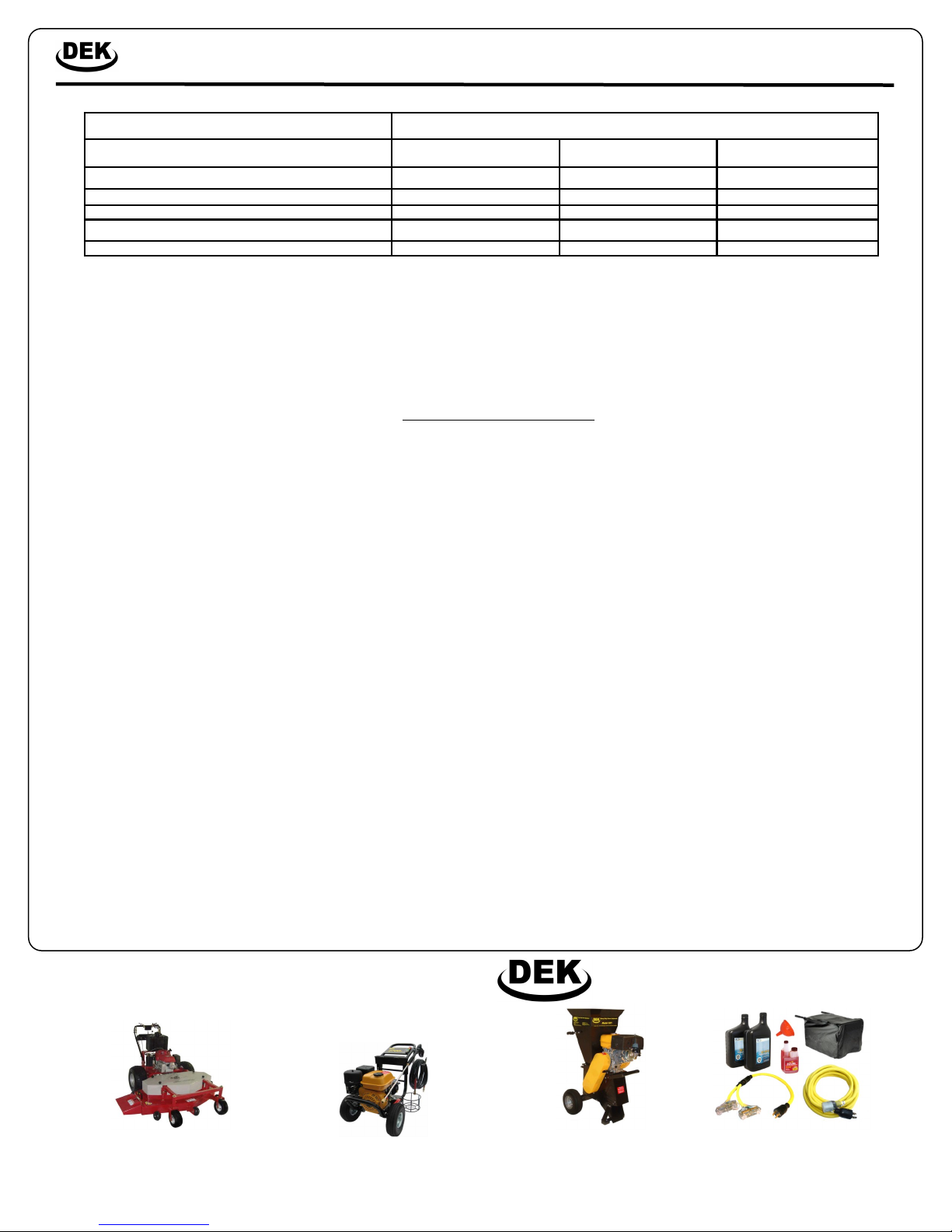
Heavy Duty Power Equipment
Commercial Lawn Mowers Heavy Duty Pressure Washers Rental Grade Chipper Shredders Generator Accessories
Other fine products offered by Heavy Duty Power Equipment
EMISSION CONTROL SYSTEM INFORMATION
The U.S. and California Clean Air Acts
EPA and California regulations require all manufacturers to furnish written instructions describing the operation and maintenance of emission control systems. The follow-
ing instructions and procedures must be followed in order to keep the emissions from your DEK engine within the emission standards. Maintenance, replacement, or
repair of the emission control devices and systems may be performed by any engine repair establishment or individual, using parts that are „„certified‟‟ to EPA standards.
The emission control systems on your DEK engine were designed, built, and certified to conform with EPA and California emission regulations. We recommend the use of
genuine DEK parts whenever you have maintenance done. These original-design replacement parts are manufactured to the same standards as the original parts, so you
can be confident of their performance. The use of replacement parts that are not of the original design and quality may impair the effectiveness of your emission control
system. A manufacturer of an aftermarket part assumes the responsibility that the part will not adversely affect emission performance. The manufacturer or re-builder of
the part must certify that use of the part will not result in a failure of the engine to comply with emission regulations.
This manual suits for next models
11
Table of contents
Other DEK Portable Generator manuals


