Toll Free: 1-866-DELAVAN (335-2826) • PH: 612-333-3189 • Toll Free Fax: 1-888-726-5906 • Fax: 612-333-3231
Document HD Magnum Install 3.15.06
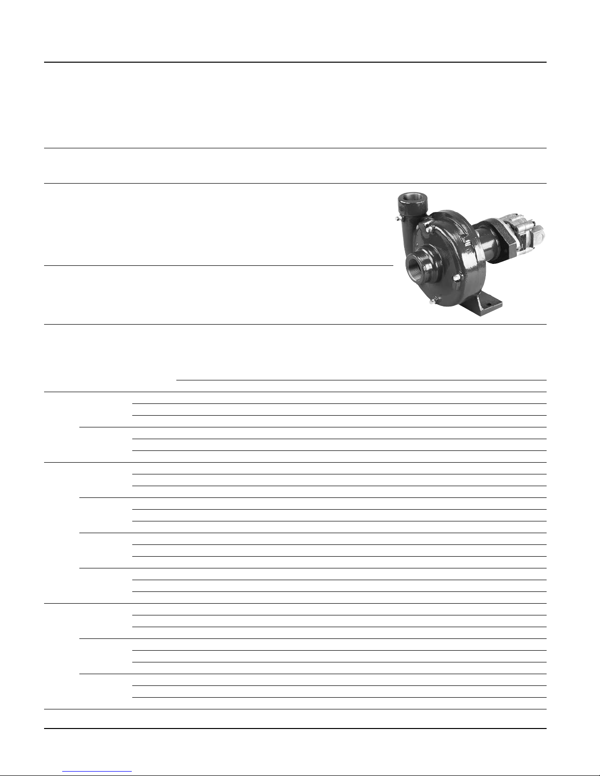
Hydraulically Driven Centrifugal Pumps
9
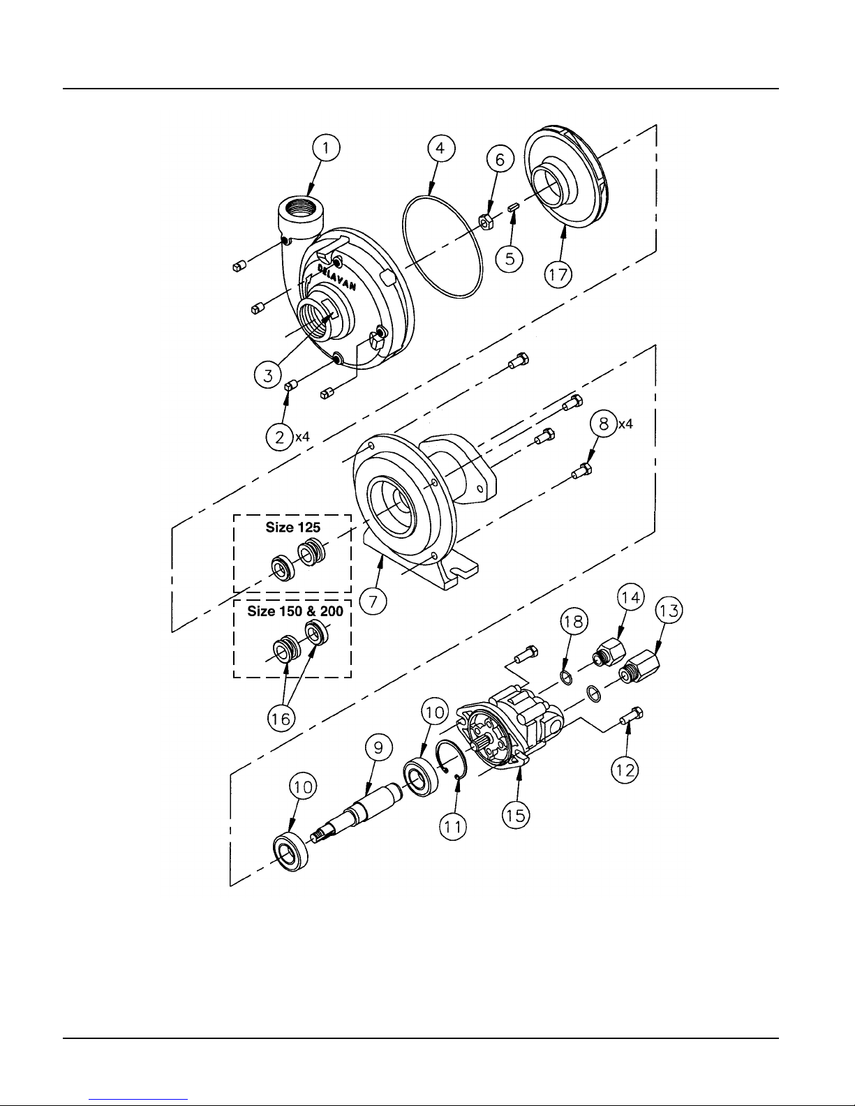
1 Volute Casing .......................................... 1
Size M125: 1-1/4”..................... I34-001
Size M150: 1-1/2”..................... I37-025
Size M200: 2” ........................... I39-025
2 1/8” NPT Pipe Plug ....................... 25785 4
3 Caution Label ................................. 35276 1
4 Frame O-ring Seal ....................... I34-003 1
5 3/16” Square Key......................... I34-005 1
6 Hex Nut ................................................... 1
Size M125: 3/8-24.................... I34-007
Size M150 & M200: 1/2-13 ...... I37-005
7 Frame .......................................... I34-012 1
8 3/8-16 X 3/4” Hex Head Screw ...... 34916 4
9 Shaft........................................................ 1
Size M125 ................................ I34-014
Size M150 & M200: .................. I37-014
10 Sealed Ball Bearing......................... 16228 2
11 Internal Retaining Ring..................... 26548 1
12 3/8-16 X 1” Heax Head Screw...... I34-017 2
13 Outlet NPT Adapter Assembly
with Check Valve 7/8-14 X 1/2” ... I34-060 1
14 Inlet NPT Adapter 3/4-16 X 1/2” ... I34-050 1
Item Part
# Description Number Qty
15 Hydraulic Motor ........................................ 1
With Rear Ports:
5-7 GPM PM21 Motor............... I34-029
7-10 GPM PM37 Motor............. I34-030
10-13 GPM PM45 Motor........... I34-031
12-15 GPM PM58 Motor........... I34-032
With Side Ports:
12-15 GPM PM58B Motor ........ I34-033
13-18 GPM PM70B Motor ........ I34-034
16 Seal Assembly.......................................... 1
Size M125: Viton/Silicon Carbide .. I34-010
Size M125: Viton/Ceramic ............ I34-011
Size M150 & M200: Viton/Silicon
Carbide........................................ I37-010
Size M150 & M200: Viton/
Ceramic ....................................... I37-011
17 Impeller Assembly..................................... 1
Size M125: 1-1/4” Nylon .............. I34-040
Size M125: 1-1/4” Polypropylene.. I34-043
Size M150: 1-1/2” Nylon .............. I37-040
Size M150: 1-1/2” Polypropylene with
SS Support Insert ........................ I37-043
Size M150: 1-1/2” Polypropylene.. I37-047
Size M200: 2” Nylon..................... I39-040
Size M200: 2” Polypropylene with
SS Support Insert ......................... I39-043
Size M200: 2” Polypropylene ........ I39-049
18 Adapter O-ring Seal .................................. 1
3/4” .......................................... 31351-15
7/8” .......................................... 31351-16
Item Part
# Description Number Qty
Repair Kits
Part Number Description
RK-M125VC Repair Kit with Viton/Ceramic Seals for M125
RK-M125VS Repair Kit with Viton/Silicon Carbide Seals for M125
RK-M215VC Repair Kit with Viton/Ceramic Seals for M150 & M200
RK-M215VS Repair Kit with Viton/Silicon Carbide Seals for M150 & M200
904003 Hydraulic Motor Bypass Valve Assembly
904804 Hydraulic Motor Seal Kit
904824 Hydraulic Motor Bearing Kit (includes bearings and seal kit) ......