Delavan PowerFLO 7800 Series Use and care manual
PowerFLO™7800 Series
Installation • Operation • Repair • Parts
12 Volt DC Motor-Driven Diaphragm Pumps
3.70
94
3.67
93.2
2.13
54.1
3.17
80.5
4.00
101.6
2.25
57.2
7.58
192.5
2.87
73
.70
17.8
3.70
94
3.67
93.2
2.13
54.1
2.25
57.2
3.17
80.5
4.00
101.6
8.84
224.5
2.87
73
1.96
49.8
3.77
95.8
3.67
93.2
2.13
54.1
4.07
103.4
7.58
192.5
3.17
80.5
4.00
101.6
2.25
57.2
3.00
76.2
.58
14.6
3.77
95.8
3.67
93.2
2.13
54.1
4.07
103.4
2.25
57.2
3.17
80.5
4.00
101.6
8.84
224.5
3.00
76.2
1.83
46.6
Motor
Type: 12 VDC, permanent magnet, totallyenclosed,
non-ventilated
Leads: 16 AWG, 6” long
Duty Cycle: See Heat Rise graph
Temperature Limits: Motor is not equipped with thermal
protection. For user safety, optimal performance, and maximum
motor life, the motor surface temperature should not exceed
150°F (66°C) (See Heat Rise graphs).
Pump
Type: 3 chamber positive displacement diaphragm pump, self
priming, capable of being run dry, demand or bypass model.
Liquid Temperature: 140°F (60°C) Max.
Priming Capabilities: 14 feet (4 m)
Max Pressure: 60 PSI
Inlet/Outlet Ports:
7801/7802/7822: Quick Attach (See chart on right)
7811/7812: 3/8” FNPT
Materials of Construction
Housing: Polypropylene Diaphragm: Santoprene
Valves: Viton Fasteners: Stainless steel
Weight
6 lbs (2.7 kg)
Quick Attach Nylon Inlet/Outlet Port Fittings
Heat Rise
Approximate values, actual values will vary with ambient temperature.
Recommended
Shell Temperature
Limit
Time (Minutes)
0
60
80
100
120
140
160
180
200
10 20 30 40 50 60 70 80 90 100 110 120
Temperature (ºF)
6.19 Amps
Item # Description
3DFA38 5/8” QA x 3/8” HB Straight Fitting
w/ O-Ring, Nylon
3DFA12 5/8” QA x 1/2” HB Straight Fitting
w/ O-Ring, Nylon
3DFE38 5/8” QA x 3/8” HB Elbow Fitting
w/ O-Ring, Nylon
3DFE12 5/8” QA x 1/2” HB Elbow Fitting
w/ O-Ring, Nylon
3DFF38 5/8” QA x 3/8” FNPT Straight Fitting
w/O-Ring, Black Nylon
3DFF12 5/8” QA x 1/2” FNPT Straight Fitting
w/ O-Ring, Black Nylon
Dimensions Inches (mm) Weight 6 lbs (2.7 kg)
The PowerFLO Series 7800 pump is controlled by a built-in
pressure sensing demand switch. When a faucet or valve
is opened down stream of the pump, line pressure drops
thus starting the pump automatically. Conversely, when the
valve shuts, the line pressure increases turning the pump off
automatically. The pressure switch actuates in response to the
pump outlet pressure at a predetermined and preset pressure.
The pump label indicates the predetermined ON and OFF
pressures. Typically, the OFF pressure is accurately set at the
Factory and the ON pressure is within an allowable range below
that value. In response to the characteristics of the system
in which the pump is installed, the flexibility and length of the
tubing, the faucet or valves and the duration that they are open;
these pressure settings may vary. Therefore, variation in pressure
setting is expected with use and over time.
Standard Warranty
Delavan warrants PowerFLO Series Pumps for a period of two
years from date of manufacture.
All products sold by Delavan are warranted only to purchasers
from Delavan for resale or for use in purchasers’ own business
or original equipment manufacture, against defects in
workmanship or materials under normal use, maintenance and
service (rental use excluded).
The sole and exclusive obligation of Delavan under this or any
implied warranty shall be to replace or, at its option, to repair,
without charge, any product which is determined by Delavan
to be defective in workmanship or materials after the product is
returned to the Delavan factory*, shipping costs prepaid.
In no event shall Delavan be liable to any person for indirect
or consequential damages or for injury or commercial loss
resulting from any use or inability to use any Delavan product.
Delavan expressly negates any other warranty, express or
implied, including any warranty of merchantability or fitness for
a particular purpose, or arising from any course of dealing or
custom or usage of trade.
No person, including any dealer or representative of Delavan,
is authorized to make any representation or warranty on behalf
of Delavan in addition to or inconsistent with these provisions.
Purchasers to whom these provisions apply agree to hold
Delavan harmless from claims by their customers in excess of
the obligations of Delavan expressly set forth herein
* Important return safety instructions:
When you return your pump for warranty or repair, you must
always do the following:
1. Flush chemical residue from the pump
(best done in the field).
2. Tag pump with type of chemicals having been sprayed
3. Include complete description of operation problem, such as
how pump was used, symptoms of malfunction, etc.
Since pumps can contain residues of toxic chemicals these
steps are necessary to protect all the people who handle return
shipments, and to help pinpoint the reason for the breakdown.
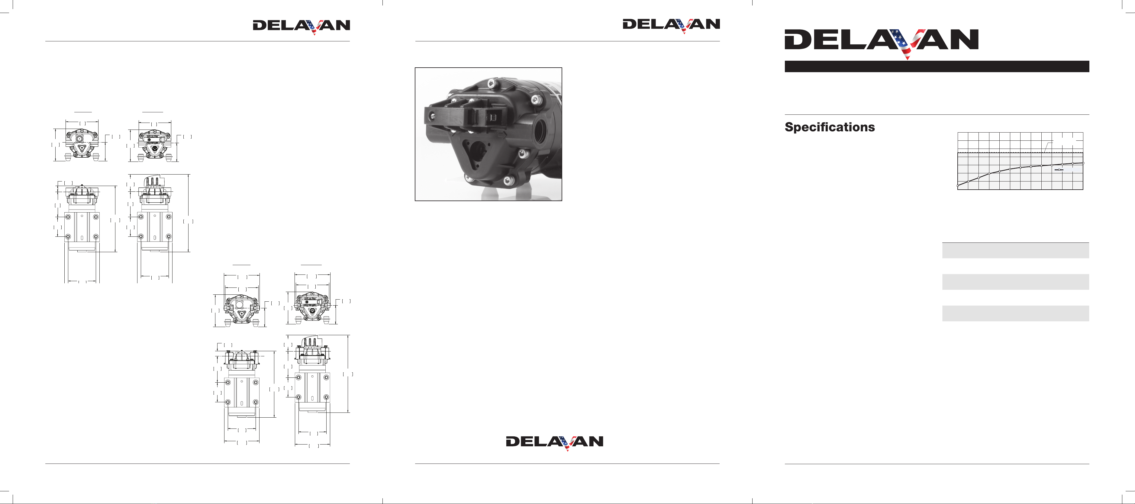
Pressure Sensing Demand Switch
www.delavanagpumps.com
Bypass Demand
PowerFLO™7800 Series PowerFLO™7800 Series
Toll Free: 1-866-DELAVAN (335-2826) •Toll Free Fax: 1-888-726-5906 •delavanagpumps.com
Toll Free: 1-866-DELAVAN (335-2826) •Toll Free Fax: 1-888-726-5906 •delavanagpumps.comToll Free: 1-866-DELAVAN (335-2826) •Toll Free Fax: 1-888-726-5906 •www.delavanagpumps.com
Threaded Port Pump
Quick Attach Port Pump
Bypass Demand

Toll Free: 1-866-DELAVAN (335-2826) •Toll Free Fax: 1-888-726-5906 •delavanagpumps.com
Mounting:
Determine the optimum location for your pump.
1. The pump should be mounted in a dry place and away
from any source of heat. If an enclosure is used, special
instructions for cooling the motor may be necessary. Consult
the Factory.
2. Do not subject the pump to extreme high or low (freezing)
temperatures while in operation. (Operating ambient
temperature range is 32° F to 115°F).
3. The pump may be mounted horizontally with the outlet port on
the right when viewed from the pump end or with the pump
above the mount, or vertically with the pump above or below
the motor.
Plumbing:
1. Use suction hose on inlet of pump. We recommend use of
flexible tubing with proper pressure rating.
2. Pump will prime only if all pressure is relieved from outlet port.
3. It is recommended that pure water be pumped or an in-line
sediment filter (50 mesh) be installed at the inlet side to keep
foreign debris out of the system. If a check valve is installed
in the plumbing, it must have a cracking pressure of no more
than 2 psi (0.14 bar).
4. Avoid any sharp bends which may crimp tubing and restrict
flow. Use 90° elbow fittings if necessary.
5. The pump should always be mounted prior to any
components which could introduce particles to the water;
thus, preventing them from entering the pump chambers and
possibly causing clogging.
Electrical:
1. The 7800 series pumps are designed for intermittent duty.
Make sure that “OFF” periods are sufficient. Refer to Rapid
ON/OFF Operation. Consult the factory for particular data and
design criteria.
2. Be sure power supply used is adequate for the application.
3. Pump ratings are based off alternator charged battery which
supplies 13.7 volts.
4. Each single drop in voltage is a reduction in motor speed thus
reducing pump performance.
(1 volt decrease = 200-300 loss in RPM)
5. Higher operating flow and pressure increases amp draw.
Installation and Operation
Precautions:
1. The pump is equipped with a pressure sensing demand
switch that controls the maximum operating pressure.
2. In addition, never subject the pump to pressures above 125
PSI (8.5 bars).
3. As long as there is inlet water pressure, the pump will not stop
forward flow of water even if the motor is turned off. Be sure
the system has positive means of shutting off water supply.
4. Do not operate pump in an explosive environment. Arcing
from the motor brushes, switch or excessive heat from an
improperly cycled motor may cause an explosion.
5. Do not locate the pump motor near low temperature plastics
or combustible material. The surface temperature of the motor
may exceed 250°F (120°C).
6. Do not pump gasoline or other flammable liquids. Pump head
materials are designed for use with water only. Do not use
with petroleum products.
7. Do not assume fluid compatibility. If the fluid is improperly
matched to the pumps’ elastomers, a leak may occur.
8. To prevent electrical shock, disconnect power before initiating
any work. In the case of pump failure, the motor housing and/
or pump fluid may carry high voltage to components normally
considered safe. Therefore, always consider electrical shock
hazard when working with and handling electrical equipment.
If uncertain, consult an Electrician. Electrical wiring should only
be done by a qualified electrician per local and state electrical
codes.
Installation Recommendations Installation and Operation
1. Turn off water supply.
2. Cut flexible tubing in sufficient length to avoid any stress on
the tubing where it connects to the pump or the fitting on any
accessory.
3. Insert tubing into pump ports. If fittings are John Guest type,
be sure tubing is inserted past the resistance point until it
bottoms out against the port stop. If compression fittings
with threaded nuts are used, insert tubing until it bottoms out
in the port and hand tighten the compression nut until the
connection is tight. Then use a wrench to tighten the nut 1/2
turn clockwise or follow the wrench tightening instructions
provided by the fitting manufacturer.
4. The pump is now ready for operation. Turn on water supply to
allow water to flow to the pump.
5. If the power source is a transformer, plug the appropriate
supplied/approved transformer into the receptacle and
connect the pump to the transformer. If the power source is
not a transformer, connect the pump to the appropriate power
source. Open the discharge or dispensing valve. Allow water
to circulate, purging any entrapped air.
6. The pump will now start building pressure. Operating pressure
will vary with flow rate, flow valve, feed-water pressure and line
voltage. Check for fitting leaks.
7. If compression fittings with threaded nuts are used, observe
any leaks after pump has run for approximately 15 minutes.
Further tighten compression nuts approximately 1/8 to 1/4
of a turn on all fittings in the system. Wait 15 minutes and
repeat the leak check. Note: Further adjustments should
not be necessary although it may take several days of
operation before all the air has been purged and the system is
stabilized.
8. Adjusting the Pressure Switch. Should the pressure switch
OFF setting vary with use and time to an unsuitable value,
it may be adjusted for optimum performance. Turn the
setscrew clockwise to increase the OFF pressure setting
and counter clockwise to decrease. The screw should not
be adjusted more than one half turn without consulting the
Factory. Excessive adjustment of the pressure switch could
cause low system pressure, rapid cycling ON/OFF operation,
and reduced pump and motor life. Damage may occur. The
Warranty does not cover improper adjustment of the pressure
switch.
Servicing:
Every Year: Check system against operating standards.
Every 2-3 Years: We recommend replacing the diaphragm
and checking against operating standards.
Troubleshooting Guide
Pump will not Start
Check:
•Correctvoltage (±10%) and electrical connections
•Fuseor breaker
•Pressureswitch operation and correct voltage at switch
or motor for open or grounded circuit
•Lockeddrive assembly
Pump will not Prime (No discharge with motor running)
Check:
•Debrisin strainer
•Restriction(kinks) in inlet/outlet tubes
•Debrisor swelling in inlet/outlet valves
Pump will not Shut Off (Output line closed and no leaks)
Check:
•Airtrapped in outlet line or pump head
•Correctvoltage to pump
•Debrisin pump inlet/outlet valves
•Loosedrive assembly or pump head screws
•Pressureswitch operations/adjustments
Leaks from Pump Head or Switch
Check:
•Loosescrews at switch or pump head
•Switchdiaphragm ruptured or pinched
•Punctureddiaphragm if is present
Replacement Parts
7801,7811,7802,7812,7822
1Lower Housing ............................................................................................................................................ 1
7801/7811 Demand or Bypass ....................................................................................... LHA-7801
7802/7812 Demand or Bypass ....................................................................................... LHA-7802
7822/7823 Demand or Bypass ....................................................................................... LHA-7822
2Valve Assembly ........................................................................................................................................... 1
7800 Series (all models) .................................................................................................. VHA-7800
3Upper Housing ............................................................................................................................................ 1
7801/7802/7822 Series w/Pressure Switch...............................................................UHA-7802-PS
7801/7802/7822 w/Bypass ........................................................................................ UHA-7802-B
7811/7812/7832 Series w/Pressure Switch...............................................................UHA-7812-PS
7811/7812/7832 Series w/Bypass.............................................................................. UHA-7812-B
4Mounting Screws .......................................................................................................................................
8-32 X 1”.......................................................................................................................... J78-051 4
10-32 X 1 1/2“.................................................................................................................. J78-050 3
5Complete Pump Head w/Threaded Ports.................................................................................................... 1
7811 w/Pressure Switch ............................................................................................. PH-7811-PS
7811 w/Bypass............................................................................................................. PH-7811-B
7812 w/Pressure Switch ............................................................................................. PH-7812-PS
7812 w/Bypass............................................................................................................. PH-7812-B
Complete Pump Head w/Quick Attach Ports .............................................................................................. 1
7801 w/Pressure Switch ............................................................................................. PH-7801-PS
7801 w/Bypass............................................................................................................. PH-7801-B
7802 w/Pressure Switch ............................................................................................. PH-7802-PS
7802 w/Bypass............................................................................................................. PH-7802-B
7822 w/Pressure Switch ............................................................................................. PH-7822-PS
7822 w/Bypass............................................................................................................. PH-7822-B
612 VDC Motor ............................................................................................................................................. 1
7800 Series w/Connector, No Switch, ............................................................................. M12-78B
7800 Series w/Switch and Connector............................................................................... M12-78C
7Pressure Switch .......................................................................................................................................... 1
7800 Series (all models) .................................................................................................7800-PSW
Item Description Part Number Qty
PowerFLO™7800 Series PowerFLO™7800 Series PowerFLO™7800 Series
Toll Free: 1-866-DELAVAN (335-2826) •Toll Free Fax: 1-888-726-5906 •delavanagpumps.com
Toll Free: 1-866-DELAVAN (335-2826) •Toll Free Fax: 1-888-726-5906 •delavanagpumps.com
This manual suits for next models
1
Other Delavan Water Pump manuals


Popular Water Pump manuals by other brands

BVA Hydraulics
BVA Hydraulics PE0501T instruction manual

EBARA
EBARA 3E Series Original instructions

Champion Power Equipment
Champion Power Equipment 100742 Operator's manual

SPIDO
SPIDO Subinox 6 instruction manual

SAMES KREMLIN
SAMES KREMLIN REXSON SH930 user manual

Tallas Pumps
Tallas Pumps P1 300 Instruction for installation and maintenance


