Delfi P.T.S. Installation instructions
OPERATOR and MAINTENANCE MANUAL
DELFI P.T.S. PORTABLE TOURNIQUETSYSTEM
PORTABLETOURNIQUET
SYSTEM
PRESSURE
DEFLATE
INFLATE
TIME
P.T.S.
REF9-2100-001
U.S. PATENTS 6,213,939; 5,931,853; 5,649,954; 4,469,099; PAT. PEND. and FOREIGN PATENTS
Delfi
medical
innovations inc.
Delfi Medical Innovations Inc.
Vancouver BC, Canada
800-933-3022 (US & Canada)
+ 604-742-0600 (Global)
Fax. + 604-742-3800
www.delfimedical.com

LIMITED ONE YEAR WARRANTY(U.S.A. only)
SCOPE OFWARRANTY
DelfiMedicalInnovationsInc. (‘Delfi’) warrantsthe P.T.S. PortableTourniquet System(‘product’) for one
year fromdate ofpurchase. During the warranty period, Delfiwill repairor replace, at itsoption, any product
which isdefectiveinmaterialsor workmanshipor which failsto meet the published specification for that
model.ThisLimited Warranty ismade onlyto the originalpurchaser ofthe product and isnon-transferable.
The remediesdescribed inthe Limited Warranty are the exclusiveremediesfor breach ofwarranty. THIS
WARRANTY SHALL NOT APPLY TO ANY PRODUCT WHICH HAS BEEN ALTERED, MODIFIED,
DISASSEMBLED OR SERVICED BY ANYONE OTHER THAN DELFI STAFF IN ANY WAY, OR WHICH
HAS BEEN SUBJECTED TO MISUSE OR ABUSE.
DISCLAIMER OFIMPLIED WARRANTIES
The foregoing Express Limited Warranty isgiven inlieu ofany and all other express or implied warranties.
DELFI MAKES NO OTHER WARRANTIES INCLUDING THE IMPLIED WARRANTIES OF
MERCHANTABILITY OR FITNESS FOR A PARTICULAR PURPOSE.
LIMITATION OFREMEDIES
In no caseshall DelfiMedicalInnovationsInc. be liablefor any specialincidentalor consequentialdamages
whether based on breach of warranty or other legaltheory. Somestatesdo not allowlimitationson warranties
or on remediesfor breach in certain transactions. In such states, the limitsin thisparagraph and the preceding
paragraph do not apply.
WARRANTY CLAIMS
In the event ofa warranty claim within the warranty period please take the following steps:
1. NotifyCustomer Service Department, DelfiMedicalInnovationsInc. at 800-933-3022. Pleaseprovide
detailsabout the nature ofthe problemand include the product serialnumber. Upon receipt ofthis
information, Delfiwill provide a date for service or a return shipping authorization.
2. Upon receipt ofthe shipping authorization, forward the equipment, freight prepaid, to the location specified
in the shipping authorization.
Your compliance with these stepswill help assure that you receive prompt warranty service for your product.
WARRANTY(OUTSIDE U.S.A.)
Please contact Delfifor warranty information.
Unit SerialNumber _________________
AC Power Supply SerialNumber _________________

1
TABLE OFCONTENTS
SECTION 1.0: DELFI PORTABLE TOURNIQUETSYSTEM (P.T.S.) GENERAL INFORMATION.........2
1.1 INTENDED USE...........................................................................................................2
1.2 CONTRAINDICATIONS................................................................................................2
1.3 PRECAUTIONS IN USE................................................................................................2
1.4 ADVERSE EFFECTS....................................................................................................3
SECTION 2.0: P.T.S. INSTALLATION AND OPERATING INSTRUCTIONS..........................................4
2.1 SPECIFICATIONS........................................................................................................4
2.1.1 POWER REQUIREMENTS..........................................................................4
2.1.2 PERFORMANCE.........................................................................................4
2.1.3 SIZE............................................................................................................4
2.1.4 ENVIRONMENTAL......................................................................................4
2.2 INITIAL INSPECTION...................................................................................................4
2.3 CONTROLS, INDICATORS, DISPLAYS, AND CONNECTORS....................................5
2.4 INITIAL SETUP.............................................................................................................9
2.5 FUNCTIONAL AND CALIBRATION CHECK................................................................9
2.5.1 AC POWER CONNECTION AND INDICATOR:...........................................9
2.5.2 POWER-UP SEQUENCE AND SELF-TESTS:.............................................9
2.5.3 PRESSURE SET POINT ADJUSTMENT:....................................................9
2.5.4 TIME LIMIT SET POINT ADJUSTMENT:...................................................10
2.5.5 CALIBRATION CHECK:.............................................................................10
2.5.6 “PRESSURE LOW” and “CUFF LEAK” ALARM CHECK:...........................11
2.6 PRESSURE AND TIME DEFAULTS...........................................................................11
2.7 OPERATION...............................................................................................................11
2.8 ALARM CONDITIONS................................................................................................13
2.8.1 ALARM SILENCE FUNCTIONS.................................................................17
2.8.2 INTERNAL HARDWARE FAILURES.........................................................17
2.8.3 PRESSURE HIGH or LOWALARMS.........................................................17
2.8.4 LEAK ALARMS..........................................................................................17
SECTION 3.0: P.T.S. MAINTENANCE INSTRUCTIONS.......................................................................18
3.1 GENERAL MAINTENANCE INFORMATION..............................................................18
3.2 PERIODIC MAINTENANCE........................................................................................18
3.2.1 CLEANING................................................................................................18
3.2.2 INSPECTION.............................................................................................18
3.2.3 FUNCTIONAL AND CALIBRATION CHECKS............................................18
3.3 CALIBRATION............................................................................................................18
3.4 LEAK TESTING..........................................................................................................19
3.5 BATTERY TESTING and REPLACEMENT.................................................................20
3.5.1 BATTERY TESTING..................................................................................20
3.5.2 BATTERY PACK REPLACEMENT............................................................20
3.6 TROUBLESHOOTING GUIDE....................................................................................21
3.7 INTERNAL HARDWARE SERVICING........................................................................23
3.8 WARNINGS, CAUTIONS, LABELS, and SYMBOL DEFINITIONS..............................23
FIGURES and TABLES:
Figure 2.1 P.T.S. Controls, Indicators, Displays, and Connectors------------------------------------------- 7
Figure 2.2 P.T.S. Pressure and Time Display Detail ------------------------------------------------------------ 8
Figure 2.3 P.T.S. Message Display Detail ------------------------------------------------------------------------- 8
Figure 3.1 Labels--------------------------------------------------------------------------------------------------------- 23
Table 2.1 AlarmConditions------------------------------------------------------------------------------------------- 13
Table 3.1 Troubleshooting -------------------------------------------------------------------------------------------- 21

2
SECTION 1.0:DELFI PORTABLE TOURNIQUETSYSTEM(P.T.S.)
GENERALINFORMATION
NOTE: Use this tourniquet system according to the policies in your practice setting. The following
information on intended use, precautions, contraindications, and adverse effects are offered as a
guide to assist in this process.
1.1 INTENDED USE
The DelfiPortableTourniquet System(P.T.S.) isintended to be used by qualified medicalprofessionalsto
temporarilyocclude blood flowinapatient'sextremity during surgicalprocedureson that extremity.
Tourniquetsare generallyused for operationslasting less than 90 minutes.Tourniquetshavebeen found
usefulin producing a bloodless operation field in surgicalproceduresinvolving the extremitiesincluding:
- Reduction ofcertain fractures- Kirschner wire removal
- Tumor and cyst excisions- Knee joint replacements
- Arthroscopy ofcertain joints- Replacement offinger joints
- Bone grafts- Amputations
- Subcutaneousfasciotomy - Nerve injuries
- Tendon repair - Totalwrist joint replacement
WARNING: Do not use tourniquet cuffs to control the distal flow of CO2or any other gases used as a
distention media. Tourniquet cuffs have not been evaluated for safety or effectiveness in controlling
gas flow beyond the surgical site during arthroscopic insufflation procedures. Possible effects of
using atourniquet cuff in this manner include serious subcutaneous emphysema proximal to the
cuff.
1.2 CONTRAINDICATIONS
Refer to the medicalliterature for possiblecontraindicationsto tourniquet use. A partiallist isprovided below,
however in every case the finaldecision to use a tourniquet restswith the attending physician.
- Open fracturesofthe leg - Post-traumatic lengthy hand reconstruction
- Severe crushing injuries- Diabetesmellitus
- Severe hypertension
- Elbowsurgery (where there isconcomitant excess swelling)
- Skin graftsin which all bleeding pointsmust be readily distinguished
- Compromised vascular circulation, e.g., peripheralartery disease
- Sickle cell disease or trait (relative contraindication, see PRECAUTIONS IN USE).
- Secondary or delayed proceduresafter immobilization.
1.3 PRECAUTIONS IN USE
•The tourniquet systemmustbe kept well calibrated and inoperablecondition. Accessoriesshouldbe
checked regularly for leaksand other defects.
•The tourniquet cuff mustnever be punctured; therefore towelclipsused near the systemmustbe
handled with specialcare.
•Cuffswith inner rubber bladdersmustbe completelyenclosed by the outer envelope to preclude
ballooning and possiblerupture ofthe bladder. Cleaning and assemblyinstructionsofthe cuff
manufacturer should be followed carefully.
•Do not usean elasticbandage for exsanguination incaseswhere thiswill causebacteria, exotoxins,
or malignant cellsto spread to the generalcirculation, or where itcoulddislodge thromboemboli that
may have formed in the vessels.
•The tourniquet cuff mustbe applied inthe proper location on the limb. Tourniquet pressure and the
timethe tourniquet isinflated on the limbshouldboth be minimized. There isadditionalpotentialrisk
to superficialnervesinunprotected areas;never applyatourniquet over an area where major nerves
may be directlycompressed againstbone (eg. peronealnervenear the proximalhead ofthe fibula).
Never applyatourniquet over the jointsofthe limb. Do not readjustan already inflated cuff by
rotating itbecausethisproducesshearing forceswhich may damage the underlying tissue. Prolonged
ischemia may lead to temporary or permanent damage to tissues, blood vessels, and nerves.

3
•Prolonged tourniquet timecan alsoproduce changesinthe coagulability ofthe blood with increased
clotting time. Alwaysminimize tourniquet time.
•Tourniquet paralysismay resultfromexcessivepressure. Insufficient pressure may resultinpassive
congestion ofthe limbwith possibleirreversiblefunctionalloss.Alwaysusethe minimumeffective
tourniquet pressure, asdescribed in the medicalliterature.
•Inflation should be done rapidly to occlude arteriesand veinsasnear simultaneously aspossible.
•Carefuland complete exsanguination reportedlyprolongspain-free tourniquet timeand improvesthe
quality ofIntravenousRegionalAnesthesia(Bier Block anesthesia). In the presence ofinfection and
painfulfractures,after the patient hasbeen inacast, and inamputationsdue to malignant tumors,
exsanguination before tourniquet application may be done without the useofan elasticbandage by
elevating the limb for 3 to 5 minutes.
•In caseoffailure, the tourniquet cuff mustbe fullydeflated and the limbexsanguinated againbefore
reinflation. Reinflation over blood-filled vasculature may lead to intravascular thrombosis.
•Tourniquet usersmustbe familiar with the inflation-deflation sequence when using twotourniquet
cuffsand twoP.T.S. unitstogether for IVRA (Bier Block anesthesia), sothat the wrong tourniquet will
not be released accidentally.
•Testfor hemoglobintype and levelbefore using atourniquet on patientswith sickle-cell anemia.
When the tourniquet isused for thesepatients,the limbshouldbe carefullyexsanguinated and the
PO2and pH should be closely monitored.
•Select the proper cuff size to allowfor the overlap recommended by the cuff manufacturer. Too
much or too littleoverlap may causecuff rolling and telescoping, unexpected releaseof the cuff from
the limb, inability to maintainabloodless fieldat normalpressures,and/or undesired pressure
distribution on the limb.
•The skinunder the tourniquet cuff mustbe protected frommechanicalinjury by smooth, wrinkle-free
application ofthe cuff.Ifthe tourniquet cuff isapplied over any materialthat may shed loosefibers
(such asWebril)the fibersmay becomeembedded inthe contact closuresand reduce their
effectiveness. Followthe cuff manufacturer’srecommendationsfor limb protection materialunder the
cuff.In general,alimbprotection sleevedesigned specificallyfor the cuff providesthe best
protection.
•Ifskinpreparationsare used preoperatively, they shouldnot be allowed to flownor collect under the
cuff where they may cause chemicalburns.
•Whenever the tourniquet cuff pressure isreleased, the wound should be protected fromblood surging
back by applying pressure dressingsand, ifnecessary, elevating the limb. Transient painupon
tourniquet pressure releasecan be lessened by elevation ofthe limb. Iffull color doesnot return
within 3 to 4 minutesafter release, the limb should be placed in a position slightly belowbody level.
•The deflated cuff and any underlying limb protection material should be completely removed
as soon as tourniquet pressure is released. After the cuff has been fully deflated and removed
from the patient, the unit can be set to STANDBY. Even the slightest impedance of venous
return may lead to congestion and pooling of blood in the operative field.
•Whenever IVRA (Bier Block anesthesia) isused, itisrecommended that the tourniquet remain
inflated for at least 20 minutesfromthe time ofinjection.
1.4 ADVERSE EFFECTS
Adull aching pain(tourniquet pain) may develop throughout the limbfollowing use. Stiffness,weakness,
reactive hyperemia, & skin discolouration may also occur to some degree in all patientsafter tourniquet use.
Pathophysiologicchangesdue to pressure, hypoxia, hypercarbia, and acidosisofthe tissuesoccur and
become significant after about 1 1/2 hoursoftourniquet use.
Symptomsoftourniquet paralysisare motor paralysisand loss ofsense oftouch, pressure, and proprioceptive
responses.
Intraoperative bleeding may be caused by:
•The slight impeding effect exerted by an unpressurized cuff (and itslimbprotection materialor
padding, ifused), which preventsvenousreturn at the beginning ofthe operation,
•Blood remaining in the limb because ofinsufficient exsanguination,
•Inadequate tourniquet pressure, or slowinflation and deflation, all ifwhich allowarterialblood to enter
while preventing venousreturn,
•Blood entering through the nutrient vesselsofthe long bones, such asthe femur or humerus.

4
SECTION 2.0:P.T.S. INSTALLATION AND OPERATING INSTRUCTIONS
2.1 SPECIFICATIONS
2.1.1 POWER REQUIREMENTS
Mains Line Voltage (AC Powered Mode):
90-264 VAC. 47/63 Hz.
Line current:
<0.5 A RMS at 90 VAC input.
Input Power:
20 wattsmaximum.
AC Power Adaptor:
Use only supplied AC adapter / power cord assembly DelfiREF 4-2100-013.
AC Power plug: (North America)
Hospitalgrade, 3 prong straight blade, 15 amp.
Battery Type:
Sealed 4.8V nickel-metal-hydride (NiMh) pack, 1800 milliamp hours
Use only DelfiREF 4-2100-017 battery pack.
Battery Recharge Time:
8.0 hours(typical).
2.1.2 PERFORMANCE
Cuff Pressure Range:
50-475 mmHg, 5 mmHg increments.
Pressure Accuracy:
+/- 5 mmHg.
Pressure Regulation:
+/- 10 mmHg ofset point (10 second average under non transient conditions).
Time Alarm Set Point Range:
0-240 minutes.
Timer Accuracy:
0.1% ofelapsed time.
Inflation Rate:
34 inch cylindricalcuff applied to a 30 inch thigh inflatesto 350 mmHg in less than 20 seconds.
Deflation Rate:
34 inch cuff applied to a 30 inch thigh deflatesto less than 10 mmHg in less than 25 seconds.
2.1.3 SIZE
Height: 240 mm (9.45 inches)
Width: 116 mm (4.57 inches)
Depth: 50 mm (1.97 inches)
Weight: 500 g (17.5 oz)
2.1.4 ENVIRONMENTAL
Operating temperature: 10 to 40 °C (15 to 105 °F)
Storage temperature: -20 to 40 °C ( -4 to 105 °F)
Humidity: Max80 % non-condensing
2.2 INITIALINSPECTION
Unpack the P.T.S. upon receipt and inspect the unitfor any obviousdamage that may haveoccurred during
shipment. Werecommend that thisinspection be performed by aqualified biomedicalengineer or other
person thoroughlyfamiliar with electronicmedicaldevices.If the unitisdamaged, notifythe carrier and Delfi
immediately. Ifthe initialinspection resultsare satisfactory, afunctionaland calibration check shouldbe
performed after an 8-hour charge. The attention labelcovering the pressure/timedisplay windowbutton may
be removed and discarded after the initial8 hour charge.

5
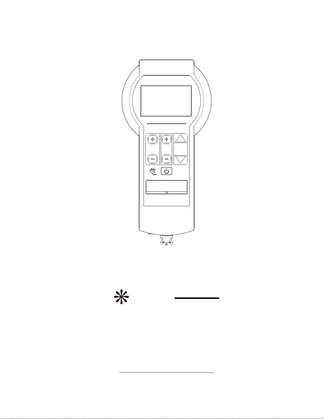
2.3 CONTROLS, INDICATORS, DISPLAYS, AND CONNECTORS
Refer to Figure 2.1 for the locationsofthe unit'scontrols,indicators,displaysand connectorsdescribed
below:
1. ‘ON/STANDBY’ Button
Turnsthe uniton or setsthe unitto standby. In standby mode (powered off), the power to all instrument
functions(i.e. inflation, deflation, etc.) isoff,but power continuesto supplythe battery charging circuitry
whenever AC power ispresent. Thisbutton will not set the unitto standby when there ispressure inthe cuff.
Ensure the cuff isfullydeflated, and the cuff and limbprotection materialhavebeen removed fromthe
patient prior to setting the unit to standby.
2. ‘PRESSURE + ’ Button
Displaysand increasesthe pressure set point inmmHg. Momentarilydepressing the ‘PRESSURE +’button
will display the pressure set point with atrailing asteriskfor 2seconds.For example, if the set point was250
mmHg and the user pressed and released the ‘PRESSURE +’button, the display wouldshow“250* ”for 2
seconds,then revert to the current cuff pressure (displayed without the trailing asterisk). Ifthe ‘PRESSURE +
’button isheldfor more than 1second, the unitwill beginincreasing the pressure set point firstby 5mmHg
then by 10 mmHg increments.If the cuff isinflating or inflated, cuff pressure will change to the newpressure
set point.
3. ‘PRESSURE – ‘ Button
Displaysand decreasesthe pressure set point, asdescribed above for the ‘PRESSURE +’ button.
4. ‘TIME + ’ Button
Displaysand increasesthe timelimitset point inminutes.Momentarilydepressing the ‘TIME +’button will
display the timelimitset point with atrailing asteriskfor 2seconds.For example, ifthe timelimitset point
was60 minutesand the user pressed and released the ‘TIME +’button, the display wouldshow“60* “for 2
seconds,then revert to the current tourniquet elapsed time. Ifthe ‘TIME +’button isheldinfor more than 1
second, the unit advancesthe time limit set point first by 5 minute then by 10 minute increments.
5. ‘TIME – ‘ Button
Displaysand decreasesthe time limit set point, asdescribed above for the ‘TIME +’ button.
6. ‘INFLATE’ Button
Inflatesthe cuff to the pressure set point and startsthe elapsed timemonitor. Momentarilydepressing the
‘INFLATE’ button immediately beginsrapid inflation ofthe cuff.
7. ‘DEFLATE’ Button
Deflatesthe cuff and stopsthe elapsed timemonitor. To prevent accidentaldeflation ofthe cuff,the
‘DEFLATE’ button hasadelay and mustbe pressed and heldfor approximately2secondsbefore the unitwill
deflate the cuff.A short tone issounded after the 2 second delay to indicate that deflation hasstarted and the
user may then releasethe ‘DEFLATE’ button. Ifthe user momentary pressesthen releasesthe ‘DEFLATE’
button, nothing happens.Ifthe user releasesthe ‘DEFLATE’ button any timeafter deflation hasbegun, the
cuff continuesto deflate to zero pressure.
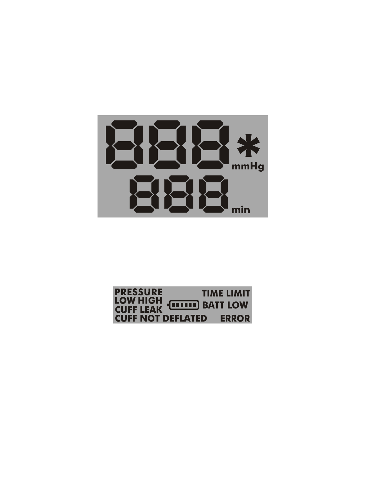
8. Pressure and Time Display
During normaloperation with no buttonsbeing pressed, the top line ofthe pressure and timedisplay shows
the current sensed cuff pressure inmmHg, and the lower line shows the number of minutesthe cuff hasbeen
inflated (tourniquet time). Anytimeatrailing asterisk(*) appearsafter the pressure or timevalue, the value
being displayed isthe set point. Under certainconditionsthe pressure and timedisplaysmay showerror
codesor alarmmessages.The tourniquet timecan be reset to zero by pressing the ‘TIME+’and ‘TIME- ‘
buttonssimultaneouslyonlywhen the cuff isdeflated. Ifthe cuff isdeflated and then reinflated without
zeroing the tourniquet timedisplay, the tourniquet timerestartsfromthe lastvalue, thereby displaying the
cumulative tourniquet time. Switching the P.T.S. to standby also resetsthe tourniquet time to zero.

6
9. Message Display
When alarm conditionsare present, the corresponding wordsare displayed and will remain displayed until the
alarmcondition iscorrected, aslong assufficient power isavailable. When operating on battery power the
battery indicator symbolisshown (see below).
10. AC Power Indicator Light
The green AC power indicator light isilluminated at all timeswhen AC power isplugged into the P.T.S., both
inon and standby modes.Note that the AC power indicator light remainsoff at all timeswhen there isno AC
power connected to the P.T.S., even during the startup routine.
11. AlarmIndicator Light
The red alarmindicator light isilluminated when any alarmcondition exists.The alarmindicator will remain
illuminated until the alarmcondition iscorrected, aslong sufficient power isavailable.
12. Battery Indicator Symbol
The battery indicator symbolinthe center of the message display (see above) isvisible when the P.T.S. ison
and operating on battery power (AC power not connected). When all six segmentsinside the battery symbol
are darkened, the battery hasafull charge. Reducing numbersofdarkened segmentsand lowbattery alarm
conditions(see Table2.1) progressivelyindicate decreasing battery capacity and need for recharging. The
battery indicator symboldisappearswhen AC power isconnected to the P.T.S.
13. Hose Connector
The hose assembly (see below) leading to the tourniquet cuff plugsin to the P.T.S. unit at the hose connector.
The hose connector isa positive locking type that makesan audible ‘click’ when properly connected.
14. Hose Assembly
One hoseassemblyissupplied with each P.T.S. unit. The malepositivelocking connector plugsinto the
hoseconnector on the P.T.S. unit(see above). The female end attachesto the tourniquet cuff. The P.T.S. is
designed, tested, and recommended for usewith Delfiand other singleport cuffshaving PositiveLocking
Connectorsonly. Usethe supplied hoseassemblyonly. An adapter isprovided with the P.T.S. unitfor
connection to calibration equipment.
15. AC Power Receptacle
The AC power receptacleislocated beside the hoseconnector. The P.T.S. isdesigned for usewith the
supplied AC power supply (see below) only; do not use any other type ofconnection to AC power.
16. AC Power Supply
An AC power supplyadapter issupplied with every P.T.S. unit. It isa sealed unit designed specifically for the
P.T.S. Contact Delfiifyour power supplyneedsservice or replacement. Plug the locking connector on the
AC power supplycord into the AC power receptacleon the P.T.S. unit(see above), and plug the AC power
cord into apower outlet (see below)whenever using the unitwhere AC power iseasilyaccessible. The AC
connector can onlybe inserted one way into the the AC power receptacle on the P.T.S. unit, and lockswith an
audible‘click’ when properlyconnected. To disconnect, press the black button on the connector and pull it
out.
17. AC Power Cord
An AC power cord with ahospitalgrade plug issupplied with every P.T.S. unit. Plug the socket end ofthe
cord into the AC power supply and the plug end into an AC power outlet.

7
Figure 2.1: P.T.S. Controls, Indicators, Displays, and Connectors
16
14
PORTABLE TOURNIQUET
SYSTEM
PRESSURE
2
15
17
3
10
5
4
6
11
13
12
7
1
9
DEFLATE
INFLATE
TIME
P.T.S.
8
8
Figure 2.2: P.T.S. Pressure and Time Display Detail
Figure 2.3: P.T.S. Message Display Detail

9
2.4 INITIALSETUP
During shipping and storage, the unit'sbattery couldbecomeweak. Prior to initialuse, the unitmustbe
plugged into AC power using the AC power supplyand cord assemblyuntil the battery isfullycharged. This
initialcharge shouldtake no more than 8hours.The battery mustbe fullycharged before any initialuse,
including any calibration checking procedures,initialchecks,or testsperformed by biomedicalengineering at
your facility.
WARNING: Use only the Delfi REF 4-2100-013 AC power supply and cord assembly supplied with your
P.T.S. Do not use any other ACpower supply or cord. Use of an improper power supply may cause
irregular operation that could be hazardous to the patient and/or user, and may permanently damage
the P.T.S. unit.
CAUTION: Avoid exposing the ACpower supply to liquids. Do not immerse in fluid. Do not allow
the ACpower supply to lie on the floor where pooling of liquids may occur. Clean by damp cloth
(alcohol or mild detergent wipe) only. The ACpower supply is resistant to occasional splashing or
dripping of fluids, but is not fluid-tight. If immersed in or exposed to excessive amounts of liquids,
the AC power supply may fail and may pose an electrical shock hazard.
WARNING: Use battery packs supplied by Delfi only. Do not use any other batteries. Use of an
improper battery pack may cause irregular operation that could be hazardous to the patient and/or
user, and may permanently damage the P.T.S. unit.
2.5 FUNCTIONALAND CALIBRATION CHECK
Each P.T.S. unitisfullytested before shipping. However, the following functionaland calibration checks
shouldbe performed by the user before the firstclinicaluseofthe P.T.S. to ensure that ithasnot been
damaged inshipping. After charging the battery asdescribed above, the unitshall produce the results
explained inthe following stepsexactlyasindicated. Failure to do soindicatesthat aproblem may existand
the device isnot to be used until necessary repair or calibration hasbeen made.
2.5.1 AC POWER CONNECTION AND INDICATOR:
Connect the AC power plug to aproperlypolarized and grounded power source with voltage and frequency
characteristicscompatiblewith the specificationslisted inSection 2.1. Observethat the green AC power
indicator light turnson.
2.5.2 POWER-UP SEQUENCE AND SELF-TESTS:
Power up the unitby pressing the ‘ON/STANDBY’ button and observethe following (the P.T.S. may be
plugged in to AC power or not for the remaining tests):
a) All display segmentsand symbolsinthe pressure and timedisplay and the message display (asshownin
Figures2.2 and 2.3) illuminate, the red alarmindicator light illuminates,and the alarmtone soundsfor 2
seconds.All displaysand tonesthen shut off for 0.5 seconds,then the cyclerepeats.Note that ifAC
power isnot connected, the green AC power indicator light doesnot comeon at any time, and ifAC
power isconnected it remainson constantly.
b) The pressure display shows "CAL" for approximately2seconds.During thistimethe unitisself-testing
specific pressure sensing calibration parameters.
c) "0" isdisplayed for both pressure and timeinthe pressure and timedisplay after the startup routine is
complete. Ifnumbersother than zero are shown in either display, the unit should be calibrated.
2.5.3 PRESSURE SETPOINTADJUSTMENT:
a) Momentarilypress the ‘PRESSURE +‘button and release(within1second). The pressure display reads
"250* "(the defaultpressure set point) for 2seconds.Note that the trailing asteriskindicatesthat the
pressure displayed isa set point, not the current cuff pressure. The pressure display then returnsto “0”.
b) Press and holdthe ‘PRESSURE +‘button. The pressure display shouldread "250* ", and after 1second
beginincreasing in5mmHg and then by 10 mmHg incrementsto the maximumpressure set point of
“475* “ mmHg.

10
c) Release the ‘PRESSURE +‘ button. Within 2 seconds, the pressure display returnsto “0”.
d) Momentarilypress the ‘PRESSURE –‘button and release(within1second). The pressure display reads
"475*" (the newpressure set point) for 2 seconds. The pressure display then returnsto “0”.
e) Press and holdthe ‘PRESSURE –‘button. The pressure display shouldread "475*", and after 1second
begindecreasing in5mmHg incrementsand then by 10 mmHg to the minimumpressure set point of“50*“
mmHg.
f)Release the ‘PRESSURE – ‘ button. Within 2 seconds, the pressure display returnsto “0”.
2.5.4 TIME LIMITSETPOINTADJUSTMENT:
a) Momentarilypress the ‘TIME +‘button and release(within1second). The timedisplay reads"60* "(the
defaulttimelimitset point) for 2seconds.Note that the trailing asteriskindicatesthat the timedisplayed
isaset point, not the current elapsed timethat the cuff hasbeen inflated. The timedisplay then returns
to “0”.
b) Press and holdthe ‘TIME +‘button. The timedisplay shouldread "60* ", and after 1second begin
increasing in5minute and then by 10 minute incrementsto the maximumtimelimitset point of“240* “
minutes.
c) Release the ‘TIME +‘ button. Within 2 seconds, the time display returnsto “0”.
d) Momentarilypress the ‘TIME –‘button and release(within1 second). The time display reads"240* " (the
newtime limit set point) for 2 seconds. The time display then returnsto “0”.
e) Press and holdthe ‘TIME –‘button. The timedisplay shouldread "240* ", and after 1second begin
decreasing in5minute and then by 10 minute incrementsto the minimumtimelimitset point of“5* “
minutes.
f)Release the ‘TIME – ‘ button. Within 2 seconds, the time display returnsto “0”.
NOTE: Anytime atrailing asterisk (*) appears, the data being displayed is the set point. Set pressure
and time will revert to the default pressure and time when the unit is powered off and powered up
again.
2.5.5 CALIBRATION CHECK:
NOTE: Every P.T.S. unit is calibrated at the factory before shipping. The unit also self-tests specific
calibration parameters upon power-up. Should apotential out of calibration condition be detected,
the unit will display error messages (see Table 2.1). However even though the unit performs aself-
test of calibration at every power-up, the following quantitative check is recommended prior to initial
use, and at regular intervals according to the policies in your practice setting.
a) Connect the P.T.S. hoseset to the P.T.S. unit, then connect the hoseto areference pressure gauge
knownto be accurate (e.g. manometer or calibrated gauge). Ifrequired, usethe PositiveLocking
Connector to Luer adapter supplied with your P.T.S. unitto connect the end ofthe P.T.S. hoseto the
reference gauge.
b) Power up the unit by pressing the ‘ON/STANDBY’ button, set the pressure set point to 50 mmHg using the
‘PRESSURE – ‘ button and press the ‘INFLATE’ button.
c) Allowthe pressure to stabilize. The pressure reading on the P.T.S. and the reference gauge shouldbe
within 5 mmHg ofeach other, and within 5 mmHg ofthe pressure set point of50 mmHg.
d) Using the ‘PRESSURE +‘button to increasethe pressure, repeat step 2.5.5(c) abovefor 250 mmHg and
475 mmHg.
e) Press and holdthe ‘DEFLATE’ button for 2secondsto deflate the unit. Disconnect the hosefromthe
P.T.S. unit. The pressure display should decrease to 0 mmHg.
f)If any stablized pressure reading isoff by more than 5mmHg during the calibration check or the pressure
display doesnot return to zero, the unit must be calibrated. See Section 3.3 below.

11
2.5.6 “PRESSURE LOW” and “CUFF LEAK” ALARMCHECK:
Connect the hoseassemblyand acuff to the P.T.S. and press the ‘INFLATE’ button. The cuff inflatesto the
defaultpressure set point of 250 mmHg. Create aleak by partiallydetaching the hosefrom the unit while the
cuff isinflated. Make the leak large enough that the pressure dropsmore than 15 mmHg belowset point.
The pumpinthe P.T.S. unitwill start asthe unit triesto maintain the set pressure. After the cuff pressure has
been more than 15 mmHg belowthe set point constantly for more than 1 second, confirmthat:
a) The pressure display flasheson/off;
b) “PRESSURE LOW” appearsin the message display (“CUFF LEAK” may also appear);
c) The red alarmindicator light isilluminated;
d) The alarmtone soundsconstantly.
Press the ‘PRESSURE +‘, ‘PRESSURE –‘, ‘TIME +‘, or ‘TIME –‘button to silence the alarm tone. Confirm
that the alarm tone restartsafter 30 seconds. Stop the leak and confirmthat the displayed pressure returnsto
the set point and stopsflashing, the “PRESSURE LOW”(and “CUFF LEAK” ifpresent) messagesdisappear,
the red alarmindicator light turnsoff, and the alarmtone stops.
2.6 PRESSURE AND TIME DEFAULTS
Changing the defaultpressure set point and timelimitset point valuesmay onlybe done after power-up and
before inflation ofthe cuff. To modify the default set points:
a) Adjustthe pressure set point to the desired defaultvalue by pressing and holding the ‘PRESSURE +‘or
‘PRESSURE – ‘ buttonsasrequired.
b) Adjust the time limit set point to the desired default value by pressing and holding the ‘TIME +‘ or ‘TIME –
‘ buttonsasrequired.
c) Momentarilypress and releasethe ‘PRESSURE +‘and ‘PRESSURE –‘buttonssimultaneously. The
alarmtone soundsbriefly, then the pressure and timeset pointsappear (with trailing asterisksymbols)in
the pressure and time displaysto indicate that the newdefault valueshave been stored.
d) After about 2 seconds, the unit resumesnormaloperation.
e) The newdefault set point valueswill nowbe present every time the machine isturned on.
2.7 OPERATION
NOTE: The P.T.S. unit should be powered up at least once each day of use to ensure the self-test
routine is performed regularly. The P.T.S. should be powered off and left plugged in to ACpower
when not in use.
a) Press the ‘ON/STANDBY’ button to turn the uniton. The unitwill execute aself-check diagnostictestas
described inSection 2.5.2 ofthismanual.Observethat all the display segmentsand the red alarm
indicator light illuminate during the self-check asshowninFigs2.2 and 2.3. Successfulcompletion ofthe
self-check indicatesthat the unit isready for use.
WARNING: If aconnected cuff is pressurized to 50 mmHg or more during power-up, the P.T.S. will
assume that asurgical procedure is in progress, adopt the pressure sensed in the cuff as the new set
point, and will automatically regulate the cuff at this pressure. Toalert the operator of this condition,
the unit will sound the alarm tone, illuminate the red alarm indicator light, flash the pressure display,
and show "PRESSURE” in the message display. The operator should immediately check the
pressure set point and readjust to the proper set point if necessary. The alarm will be cleared as
soon as the set point is examined or adjusted (‘PRESSURE +‘or ‘PRESSURE –‘button pressed
momentarily or pressed and held).
b) Connect the hose assembly and a single port cuff to the unit at the hose connector.
c) Select the appropriate tourniquet pressure and tourniquet timelimitset pointsfor the specificprocedure,
asspecified by the surgeon. The defaultset pointsfor pressure and timelimitare retrieved fromthe

12
memory during power up and are active until the user adjuststhem(see Sections2.5.3 and 2.5.4). These
default valuescan be modified by the user (see Section 2.6).
WARNING: In all cases it is essential to check the pressure and time limit set points and confirm that
they are the desired values before inflating the cuff.
For each patient, tourniquet pressure required to occlude blood flowto operativesite shouldbe set to the
minimumeffectivepressure. The minimumeffectivepressure dependson many factors,including the
location ofthe cuff (upper or lower limb), the type of cuff and quality of fitto the limb, whether the limbis
normal,hypertrophied, or obese, the patient'spreoperativesystolicpressure, and the maximum
anticipated riseinsystolicpressure during the procedure. Refer to the medicalliterature for current
techniquesfor determining the minimumeffective tourniquet pressure for each case.
d) Prepare the patient inaccordance with your established proceduresand cuff manufacturer'sinstructions.
The precautionsofSection 1and the following are offered asaguide to assistinthisprocess.In most
casesatourniquet cuff should be applied to the widest part ofthe limb to allowasmuch tissue aspossible
to liebetween the cuff and any nervesor vascular structuressusceptibleto damage. The optimum
positionsare the upper armand the proximalthird ofthe thigh. In certaincasesoffore-foot surgery, the
tourniquet cuff can be applied around the calfor to the area proximalto the malleoli.For emergency
surgery ofthe hand, asufficientlysmall tourniquet may be selected by the surgeon for fitting around the
forearm.Applyaleak-free tourniquet cuff smoothlywithout wrinklesThe hoseconnectionsshouldbe
placed sothat the hosewill not be kinked when the limbispositioned for surgery. The viability of the skin
and deeper tissuesshouldbe established prior to exsanguination ofthe limband tourniquet inflation.
Exsanguinate the limbby elevating itfor aminimumof2minutesand wrapping it, distalto proximal,
using an Esmarch, Martin, or elasticbandage. The bandage shouldcomeup approximatelyto 1in. (2.5
cm)fromthe edge of the tourniquet cuff.The elasticbandage isremoved following inflation of the cuff.If
regionalanesthesiaisbeing used, the anestheticagent or nerveblock isthen administered. The surgeon
will determine:
•When the tourniquet isto be inflated;
•What pressure isapplied;
•Howlong the tourniquet isapplied;
•Whether to allowfor intermittent aeration oftissue by deflating the cuff,and the duration of
these aeration periods;
•When to deflate and remove the tourniquet.
Appropriate tourniquet timeand the need for intermittent deflation ofthe cuff depend greatlyon the
patient'sanatomy, age, and absence ofvascular disease. In many operating rooms,itiscustomary to
prominentlynote the timeofinflation, and to warn the surgeon after acertaintimehaselapsed. Thiswill
allowthe surgeon to assess the need for further tourniquet time.
e) Press the ‘INFLATE’ button when the cuff mustbe inflated. The unitwill pressurize the cuff to the
pressure set point and start the tourniquet timeclock. Ifthe unitcannot pressurize the cuff to within15
mmHg ofthe set point inless than 45 seconds,aleak alarmwill be sounded (see Table2.1 for
information about possiblealarmconditions). The timedisplay shows the tourniquet time, and the
pressure display shows the current pressure in the cuff.
f)When the cuff mustbe deflated, press and holdthe ‘DEFLATE’ button. After holding the button for 2
seconds,the alarmtone will sound briefly, the pressure display will showthe falling pressure ofthe cuff,
and the tourniquet timeclock will stop and holdthe display ofthe tourniquet time. Remove the
tourniquet cuff and any underlying limb protection material immediately following final cuff
deflation.The timeoftourniquet cuff removalshouldbe noted, and the circulation ofthe limbshouldbe
checked.
NOTE: The elapsed tourniquet time can be zeroed after the cuff is deflated by pressing and holding
the ‘TIME+‘and ‘TIME- ‘buttons simultaneously. The alarm tone will sound briefly to indicate the
time has been zeroed.
g) After the cuff hasbeen removed, disconnect the cuff fromthe P.T.S. During normaluse, the P.T.S.
shouldnot be set to standby ifpressure ispresent inthe cuff.Once the cuff hasbeen properlydeflated,
removed fromthe patient and disconnected fromthe P.T.S., the unit can be set to standby.

2.8 ALARMCONDITIONS
There are anumber ofconditionsfor which the P.T.S. will produce visualand audiblealarms.Thoseconditions,indicationsand appropriate actionsare
showninTable2.1. The appropriate actionsindicated are based on the mostprobablecausesand shouldonlybe used asaguide. Other causesof
alarmconditionsmay indicate a need for other actions.
Table 2.1: Alarm Conditions
Condition Description Message
display
(steady)
Alarm
tone Pressure
display Time
display
Action to silence
alarm tone for 30
seconds
Action required to correct
alarm condition
High
Pressure
above set
point
The unit hasdetected
high pressure in the
cuff. High pressure is
defined aspressure
that is+15mmHg
above the pressure set
point continuously for
more than 1 second.
PRESSURE
HIGH
Constant Current
cuff
pressure,
flashing
NormalMomentarily Press
‘PRESSURE +’,
‘PRESSURE – ‘,
‘TIME +‘, or
‘TIME – ‘.
Press and hold ‘PRESSURE +’
to adjust set pressure to within
15mmHg ofsensed pressure
OR
Press and hold ‘DEFLATE’ for 2
secondsto deflate the cuff.
Alarmwill stop automatically
whenever the unit can regulate
the cuff to within 15 mmHg ofthe
pressure set point.
Low
Pressure
belowset
point
The unit hasdetected
lowpressure in the cuff.
Lowpressure isdefined
aspressure that is
15mmHg belowthe
pressure set point
continuously for more
than 1 second.
PRESSURE
LOW
Constant Current
cuff
pressure,
flashing
NormalMomentarily Press
‘PRESSURE +’,
‘PRESSURE – ‘,
‘TIME +‘, or
‘TIME – ‘.
Press and hold ‘PRESSURE – ‘
to adjust set pressure to within
15mmHg ofsensed pressure
OR
Press and hold ‘DEFLATE’ for 2
secondsto deflate the cuff.
Alarmwill stop automatically
whenever the unit can regulate
the cuff to within 15 mmHg ofthe
pressure set point.
13

Condition Description Message
display
(steady)
Alarm
tone Pressure
display Time
display
Action to silence
alarm tone for 30
seconds
Action required to correct
alarm condition
Tourniquet
time
exceeded
The unit’selapsed
timer, which advances
when the cuff is
inflated, hasreached
the time limit set point
and caused the time
alarmto activate.
TIME LIMIT
Constant NormalCurrent
tourniquet
time,
flashing
Momentarily Press
‘PRESSURE +’,
‘PRESSURE – ‘,
‘TIME +‘, or
‘TIME – ‘.
Press and hold ‘TIME +’ to
increase time limit set point,
OR
Press and hold ‘DEFLATE’ for 2
secondsto deflate the cuff.
Battery
Low
(stage 1)
The battery voltage has
dropped to a level
indicating that the unit
should be plugged into
AC power for continued
use, and to charge the
battery.
BATT LOW
2 segments
darkened in
battery
indicator
symbol.
Cycle 1s
on / 10s
off
NormalNormalMomentarily Press
‘PRESSURE +’,
‘PRESSURE – ‘,
‘TIME +‘, or
‘TIME – ‘.
Plug in AC power
OR
Press ‘ON/STANDBY’ to shut unit
down.
Battery
Low
(stage 2)
The battery voltage has
dropped to a level
indicating that the unit
may trigger a “BATT
ERROR” alarm(see
below) and shut down
at any time.
BATT LOW
1 segment
darkened in
battery
indicator
symbol.
Constant NormalNormalMomentarily Press
‘PRESSURE +’,
‘PRESSURE – ‘,
‘TIME +‘, or
‘TIME – ‘.
Plug in AC power immediately
OR
Press ‘ON/STANDBY’ to shut unit
down.
Battery
Failure The battery voltage has
dropped belowthe
threshold ofsafe
operation and hasshut
down in a safe state*
OR
The battery hasbeen
removed/disconnected.
BATT
ERROR
Battery
indicator
symbol
empty.
Constant “Err” Blank None Press ‘ON/STANDBY’ to shut unit
down. When cuff deflation is
required, disconnect hose to cuff.
Ensure that the battery is
connected properly. Plug in AC
power to attempt to recharge the
battery. Service or replace the
battery pack (see Section 3.5
below).
14

Condition Description Message
display
(steady)
Alarm
tone Pressure
display Time
display
Action to silence
alarm tone for 30
seconds
Action required to correct
alarm condition
Attempt to
power off
unit with
cuff press-
urized
The unit hasdetected
that the operator has
attempted to set the
unit to standby with
pressure remaining in
the cuff.
CUFF NOT
DEFLATED Constant
while
button
held, and
for 2
seconds
after
button
released.
Current
cuff
pressure,
flashing
NormalMomentarily Press
‘PRESSURE +’,
‘PRESSURE – ‘,
‘TIME +‘, or
‘TIME – ‘.
Press and hold ‘DEFLATE’ for 2
secondsto deflate the cuff, then
press ‘ON/STANDBY’ to shut unit
down.
Cuff
pressuri-
zed during
power up
The unit hasdetected
an approximate
pressure of50mmHg or
more in the cuff when
the unit waspowered
up. The unit assumes
a procedure isin
progress, changesthe
pressure set point to
the detected pressure,
immediately regulates
the cuff to this
pressure, and activates
alarmto alert the user
ofthe condition.
PRESSURE Constant Current
cuff
pressure,
flashing
NormalMomentarily Press
‘TIME +‘ or
‘TIME – ‘.
Momentarily press
‘PRESSURE +’ or
‘PRESSURE – ‘ button to display
pressure set point
OR
Adjust pressure set point by
pressing and holding
‘PRESSURE +’ or
‘PRESSURE – ‘.
Cuff not
fully
deflated
The unit hasdetected
pressure in the cuff
greater than 15mmHg,
60 secondsafter the
cuff hasbeen deflated.
CUFF NOT
DEFLATED Constant Current
cuff
pressure,
flashing
NormalMomentarily Press
‘PRESSURE +’,
‘PRESSURE – ‘,
‘TIME +‘, or
‘TIME – ‘.
Disconnect hose to cuff to
exhaust pressure.
15

Condition Description Message
display
(steady)
Alarm
tone Pressure
display Time
display
Action to silence
alarm tone for 30
seconds
Action required to correct
alarm condition
Leak in cuff
or hose The unit hasdetected a
large leak in a cuff
defined asthe cuff
failing to reach the
pressure set point in a
reasonable time, or the
pump running
excessively while
regulating in ‘Inflating’
or ‘Regulating’ mode
and the pressure set
point isnot being
adjusted.
CUFF LEAK
(may also
display
PRESSURE
LOW)
Constant Current
cuff
pressure,
flashing
NormalMomentarily Press
‘PRESSURE +’,
‘PRESSURE – ‘,
‘TIME +‘, or
‘TIME – ‘.
Fix leak
OR
Reduce pressure set point until
unit can maintain pressure
OR
Press and hold ‘DEFLATE’ for 2
secondsto deflate the cuff.
Calibration
failure The unit hasdetected
that the calibration in
the pressure transducer
isinvalid. The unit has
shut down in a safe
state*.
(See also Calibration
Procedure, Section 3.3)
ERROR Constant “CAL” “Err” None Disconnect the hose and press
‘ON/STANDBY’ twice to shut unit
down and restart
OR
Calibrate the unit per Section 3.3
Internal
electronic
failure
The unit hasdetected
an internalerror and
hasshut down in a
safe state*.
ERROR Constant “Err” Error code None Press ‘ON/STANDBY’ twice to
shut unit down and restart.
When cuff deflation isrequired,
disconnect hose to cuff.
* In the ‘safe state’ mode, the current pressure in the cuff is held (in the absence of leaks). The ‘safe state’ mode helps prevent unexpected
loss of occlusion during a procedure if a sudden failure occurs. See Section 2.8.2 for more detail.
16

17
2.8.1 ALARMSILENCE FUNCTIONS
Mostaudiblealarmtonesmay be silenced for 30 secondsby momentarilydepressing the ‘PRESSURE +‘,
‘PRESSURE –‘, ‘TIME +‘, or ‘TIME –‘button. At the end of the silenced period, the alarm tone will restart if
the alarm condition hasnot been corrected. The alarmtone may be silenced for additional30 second periods
asrequired.
2.8.2 INTERNAL HARDWARE FAILURES
When “Err” and anumericerror code or “CAL” and “Err” appear inthe pressure and timedisplaysduring use
or power-up, an internalhardware failure haslikelyoccurred and the P.T.S. unitisunusable. In thissituation,
itislikelythat the unithasput itselfinthe ‘safestate’ mode, inwhich the pneumaticvalveand pumpare
disabled and the current pressure inthe cuff isheld(inthe absence ofleaks). It isalsolikelythat atone will
sound under theseconditions.The ‘safestate’ mode helpsprevent unexpected loss ofocclusion during a
procedure ifa sudden failure occurs.
Although itisvery unlikely, internalhardware failuresmay alsocauseerraticoperation and/or unintelligible
displayswith or without alarms, and may or may not put the P.T.S. in the ‘safe state’ mode.
Ifeither type oferror occurs:
a) Set the unitto standby by pressing the ‘ON/STANDBY’ button. Thisremovespower fromthe internal
instrument circuitry and all instrument functions,causing the cuff to holdpressure (inthe absence of
leaks).
b) Ifrequired, attempt to restart the unit by pressing the ‘ON/STANDBY’ again to restart the unit.
c) Ifrequired to continue the procedure, clampthe hosewith ahemostat to maintaincuff pressure, then
immediately disconnect the faulty P.T.S. unit and connect a replacement unit.
d) Ifcuff deflation isrequired, disconnect the cuff fromthe P.T.S. unit.
WARNING: In all cases of internal hardware failure, erratic operation, or unintelligible displays, it is
possible that the pressure in the cuff is not accurately displayed on the P.T.S. unit and that cuff
pressure may be present even when the P.T.S. unit appears to be shut down. The user must
immediately determine if the cuff is inflated or deflated and continually monitor the cuff to ensure
patient safety. If deflation of the cuff is necessary, disconnect the hose from the P.T.S. unit or from
the cuff and confirm that the cuff deflates completely.
2.8.3 PRESSURE HIGH or LOWALARMS
A"PRESSURE HIGH" or "PRESSURE LOW"alarmwill occur when the pressure inacuff ismore than 15
mmHg fromthe pressure set point. To minimize nuisance alarmsthat can be caused by vigorousmovement
ofthe patient'slimbs, a 1 second delay hasbeen designed into alarmactuation for these conditions.
2.8.4 LEAK ALARMS
It ispossiblefor the system to haveasubstantialleak that the unitcan compensate for by continualpumping.
Thistype ofleak could be due to a hole in the cuff or hose assembly, a loose or worn hose connector, or leaks
inthe pneumaticcircuitinside the P.T.S. unit. All leaksrequire immediate attention, becausethey could
progress into atotalfailure of acuff to holdpressure at any time. To alert the operator that a substantialleak
ispresent, the “CUFF LEAK” alarm isactivated when thistype of leak iscontinuouslypresent for more than 7
seconds,even if the unitismaintaining the cuff pressure within15 mmHg of the set point. If a“CUFF LEAK”
alarmoccurs,the cuff,hoseassembly, and hoseconnectorsshouldbe checked for leaks.If an externalleak
cannot be found, test the P.T.S. unit per Section 3.4 below.

18
SECTION 3.0:P.T.S. MAINTENANCE INSTRUCTIONS
3.1 GENERALMAINTENANCE INFORMATION
Whilethe P.T.S. hasbeen designed and manufactured to high industry standards,itisrecommended that
periodicinspection, testing, and calibration (‘maintenance’) be performed asdescribed inthissection to
ensure continualsafeand effectiveoperation. Thissection alsoservesasaguide to troubleshooting and
expediting unscheduled maintenance. The maintenance intervalslisted beloware provided asaguideline;
refer also to the policiesin your practice setting for generaltourniquet maintenance proceduresand intervals.
CAUTION: Do not attempt to disassemble or open the enclosure of your P.T.S. unit. The P.T.S. is not
designed to be disassembled and serviced by anyone other than Delfi staff. Disassembly and
attempted service by anyone other than Delfi staff poses arisk of electric shock, damage to the unit,
and injury to the patient and will void all warranties. Internal parts in the P.T.S. can only be serviced
at the factory by Delfi staff. Please contact Delfi if you have problems with your P.T.S. unit that
cannot be resolved by following the maintenance and troubleshooting procedures described below.
3.2 PERIODIC MAINTENANCE
3.2.1 CLEANING
The exterior ofthe unitmay be cleaned asoften asrequired with acloth that hasbeen dampened (not
dripping) with amilddetergent. The exterior of the cuff hosemay be cleaned using amilddetergent solution
or alcohol. Tourniquet cuffsshould be cleaned in accordance with the manufacturer’sinstructions.
CAUTION: Do not attempt to clean or flush out the interior of the hose assembly. Do not allow fluids
or debris to enter the hose connectors on the P.T.S. unit or the hose assembly.
CAUTION: Avoid exposing the ACpower supply to liquids. Do not immerse in fluid. Do not allow
the ACpower supply to lie on the floor where pooling of liquids may occur. Clean by damp cloth
(alcohol or mild detergent wipe) only. The ACpower supply is resistant to occasional splashing or
dripping of fluids, but is not fluid-tight. If immersed in or exposed to excessive amounts of liquids,
the AC power supply may fail and may pose an electrical shock hazard.
3.2.2 INSPECTION
The unit should be externally inspected asfollows at least once every three months:
•Obviousexternaldamage.
•Missing or illegible labelsand warnings.
•Kinksor damage in the power cord.
•Secure connection and locking ofthe power cord plug to the receptacle on the P.T.S. unit.
•Secure connection and locking ofthe hose connectorson the P.T.S. unit to the hose assembly.
•Kinksor damage in the hose assembly.
3.2.3 FUNCTIONAL AND CALIBRATION CHECKS
The functionaland calibration checksdescribed inSection 2.5 shouldbe performed at leastonce every three
months.
3.3 CALIBRATION
Calibration should be performed every six months, or after any unscheduled maintenance.
Calibration ofthe P.T.S. allows the output signalfromthe pressure transducer to be compared againsta
calibrated pressure source. The difference between the knownpressure and the pressure measured by the
This manual suits for next models
1
Table of contents
Other Delfi Medical Equipment manuals


Popular Medical Equipment manuals by other brands

Kimberly-Clark
Kimberly-Clark M1000 Operator's manual

CMC
CMC Patient Tie-In System Important information

Osprey Medical
Osprey Medical Display, Contrast Monitoring Instructions for use

MIETHKE
MIETHKE proGAV Instructions for use

Fillauer
Fillauer 7 product manual

Weinmann
Weinmann homecare SOMNOcomfort 2 Servicing and Repair Instructions


Gilson
Gilson Minipuls 3 user guide

Gima
Gima 31204/501 manual

PHILIPS Respironics
PHILIPS Respironics Wisp manual

Cardinal Health
Cardinal Health Kangaroo ePump Quick reference guide

Physio Control
Physio Control LIFEPAK CR PLus Service manual

Fresenius Medical Care
Fresenius Medical Care 2008T BlueStar troubleshooting guide