Delios DLS 450C User manual

INSTRUCTION MANUAL
- OPERATION
- INSTALLATION
- MAINTENANCE
Carefully read these instructions
before first use.
TRANSLATED FROM
THE ORIGINAL IN
ITALIAN LANGUAGE
Code: 240.010.0018
Date: /0/201
Rev.:
DLS 300C / 450C / 600C
GB

2
Cod.: 240.010.0018
DLS 300C / 450C / 600C
IMPORTANT SAFETY INSTRUCTIONS
This manual contains important safety information, which must be followed during the installation and main-
tenance operations of the equipment.
It is compulsory for the operators to read this manual and to strictly follow the instructions contained herein,
as DELIOS s.r.l. shall not be accountable for injuries caused to people and/or damages to things or to the
equipment if the following instructions conditions are not followed.

DLS 300C / 450C / 600C
3
Cod.: 240.010.0018
Fig. 00
BATTERY PACK PV STRING 1 PV STRING 2 MAINS HOME LOADS
4
Cod.: 240.010.0018
DLS 300C / 450C / 600C
Fig. 01

DLS 300C / 450C / 600C
5
Cod.: 240.010.0018
Fig. 02
6
Cod.: 240.010.0018
DLS 300C / 450C / 600C
Fig. 03

DLS 300C / 450C / 600C
7
Cod.: 240.010.0018
Fig. 04
8
Cod.: 240.010.0018
DLS 300C / 450C / 600C
Fig. 05

DLS 300C / 450C / 600C
9
Cod.: 240.010.0018
Fig. 06

10
Cod.: 240.010.0018
DLS 300C / 450C / 600C
Fig. 07

DLS 300C / 450C / 600C
11
Cod.: 240.010.0018
Fig. 08

12
Cod.: 240.010.0018
DLS 300C / 450C / 600C
Fig. 09

DLS 300C / 450C / 600C
13
Cod.: 240.010.0018
Fig. 10
14
Cod.: 240.010.0018
DLS 300C / 450C / 600C
Fig. 11

DLS 300C / 450C / 600C
15
Cod.: 240.010.0018
TABLE OF CONTENTS
1 INTRODUCTION ...........................................................................................................................17
1.1 Fields of Application ..............................................................................................................17
1.2 Symbols Used in This Manual ..............................................................................................17
1.3 Warranty................................................................................................................................17
2 CAUTIONS ....................................................................................................................................18
2.1 Operating Environment and Restrictions ..............................................................................19
2.2 Dismantling, Removal and Disposal .....................................................................................20
2.3 Protecting Staff and Third Parties .........................................................................................21
2.4 Protection from Electric Shock ..............................................................................................22
2.5 Electromagnetic Fields and Interferences .............................................................................22
2.6 IP Protection Rating ..............................................................................................................22
2.7 Signage and Data Decals .....................................................................................................22
2.8 Residual Risks ......................................................................................................................23
3 GENERAL DESCRIPTION ............................................................................................................24
3.1 The DSL System ...................................................................................................................24
3.2 Protective Devices ................................................................................................................24
3.2.1 Anti-islanding ........................................................................................................................24
3.2.2 Earth Leakages of PV Panels ...............................................................................................24
3.2.3 Converter Earth Leakages ...................................................................................................24
3.2.4 Automatic Interlock System (IT) ............................................................................................24
3.2.5 AC BYPASS Switch ..............................................................................................................25
3.2.6 AC GRID Input Magnetic Thermal Circuit Breaker ...............................................................25
3.2.7 AC OUT Output Magnetic Thermal Circuit Breaker .............................................................25
3.2.8 DC Inputs String Switch ........................................................................................................25
3.2.9 String Fuses ..........................................................................................................................25
3.2.10 Battery Galvanic Isolation .....................................................................................................25
3.2.11 Battery Overcurrent Protective and Safety Fuse ..................................................................25
3.2.12 Battery Temperature Sensor .................................................................................................25
3.2.13 Automatic Battery Switch ......................................................................................................25
3.2.14 Additional Protective Devices ...............................................................................................25
3.3 Touch-screen Control Panel ..................................................................................................26
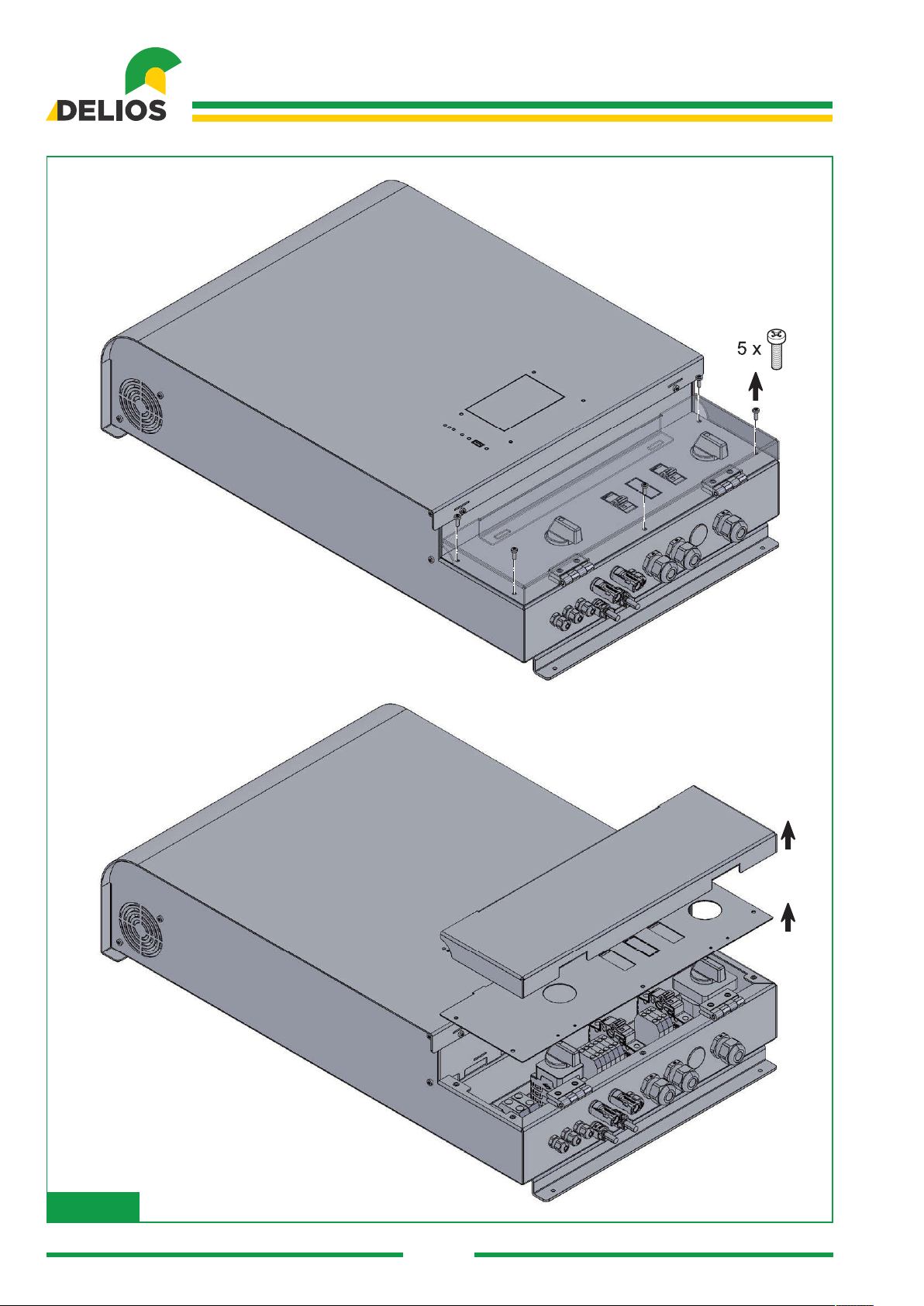
4 INSTALLATION .............................................................................................................................26
4.1 Lifting, Transport and Unloading Instructions ........................................................................26
4.2 Unpacking and Checks .........................................................................................................27
4.3 Checking the Box Contents ..................................................................................................27
4.4 Positioning the DLS ..............................................................................................................27
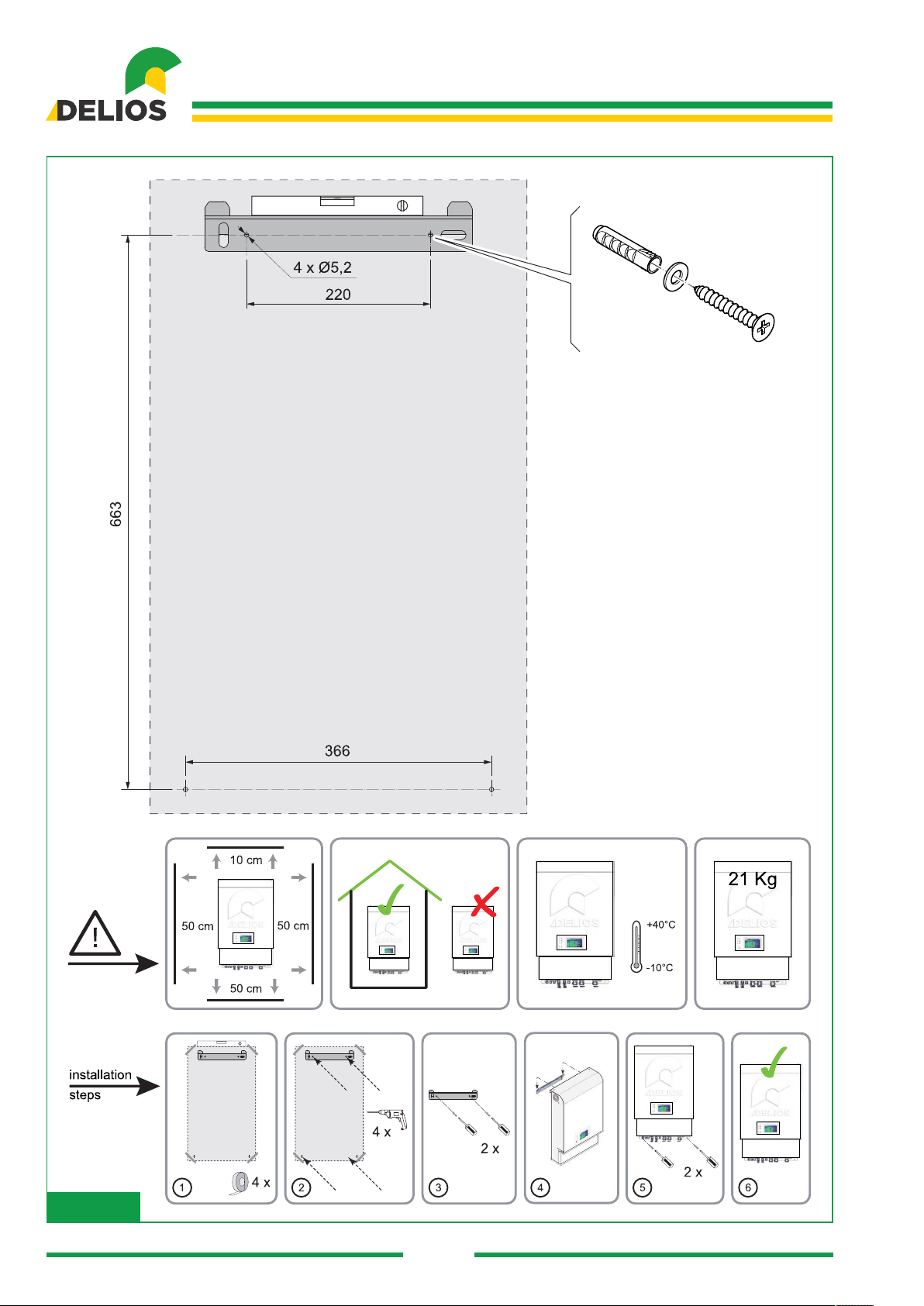
4.5 Mounting the DLS .................................................................................................................28
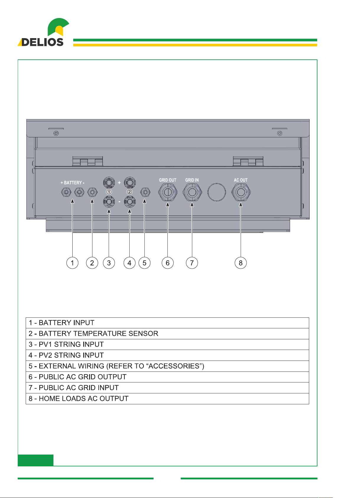
4.6 Connection ............................................................................................................................28
4.6.1 Cautions ................................................................................................................................28
4.6.2 Connection to the AC National Electricity Grid ......................................................................29
4.6.3 Connecting the PV Panels ....................................................................................................31

16
Cod.: 240.010.0018
DLS 300C / 450C / 600C
4.6.4 Connecting the 48V Lead-acid Battery .................................................................................32
4.6.5 Connecting the 48V Lithium Battery .....................................................................................33
4.7 Switching on the System .......................................................................................................34
5 CONTROL PANEL ........................................................................................................................35
5.1 General Information ..............................................................................................................35
5.2 “HOME” Screen ....................................................................................................................36
6 PROGRAMMING THE SYSTEM ...................................................................................................38
6.1 “MENU’” Structure and System Navigation ...........................................................................38
6.2 “MAIN” Menu .........................................................................................................................39
6.3 “LOGIN/LOGOUT” Menu ......................................................................................................40
6.4 “GRAPHICS” Menu ...............................................................................................................41
6.5 “INFO” Menu .........................................................................................................................42
6.6 “SETTINGS” Menu ................................................................................................................43
6.6.1 “MAIN” Menu .........................................................................................................................43
“DATEANDTMEMenu ......................................................................................................44
“AUTO-TESTMenu .............................................................................................................44
“TOOLSMenu .....................................................................................................................44
“LANGUAGEMenu ..............................................................................................................44
“FRMWAREUGRADEMenu ...........................................................................................44
“BACKU/RESTOREMenu ................................................................................................45
6.6.2 “SYSTEM” Menu ...................................................................................................................45
6.6.3 “GRID CODE” Menu .............................................................................................................45
6.6.4 “BATTERY” Menu .................................................................................................................45
“LEADMenu ........................................................................................................................45
“LTHUMMenu ..................................................................................................................46
6.6.5 “HOME AUTOMATION” Menu ..............................................................................................46
6.7 “EXPORT” Menu ...................................................................................................................47
6.7.1 “DATA” Menu.........................................................................................................................47
6.7.2 “EVENTS” Menu ...................................................................................................................47
7 ACCESSORIES .............................................................................................................................47
7.1 EXTERNAL ALARM Signal Connection ................................................................................47
7.2 .....48
8 MAINTENANCE ............................................................................................................................48
8.1 General Information ..............................................................................................................48
8.2 Switching off the System ......................................................................................................49
8.3 Replacing the Battery Fuse ...................................................................................................49
8.4 Disinstallation ........................................................................................................................50
8.5 Disposal ................................................................................................................................50
9 TROBLESHOOTING .....................................................................................................................51
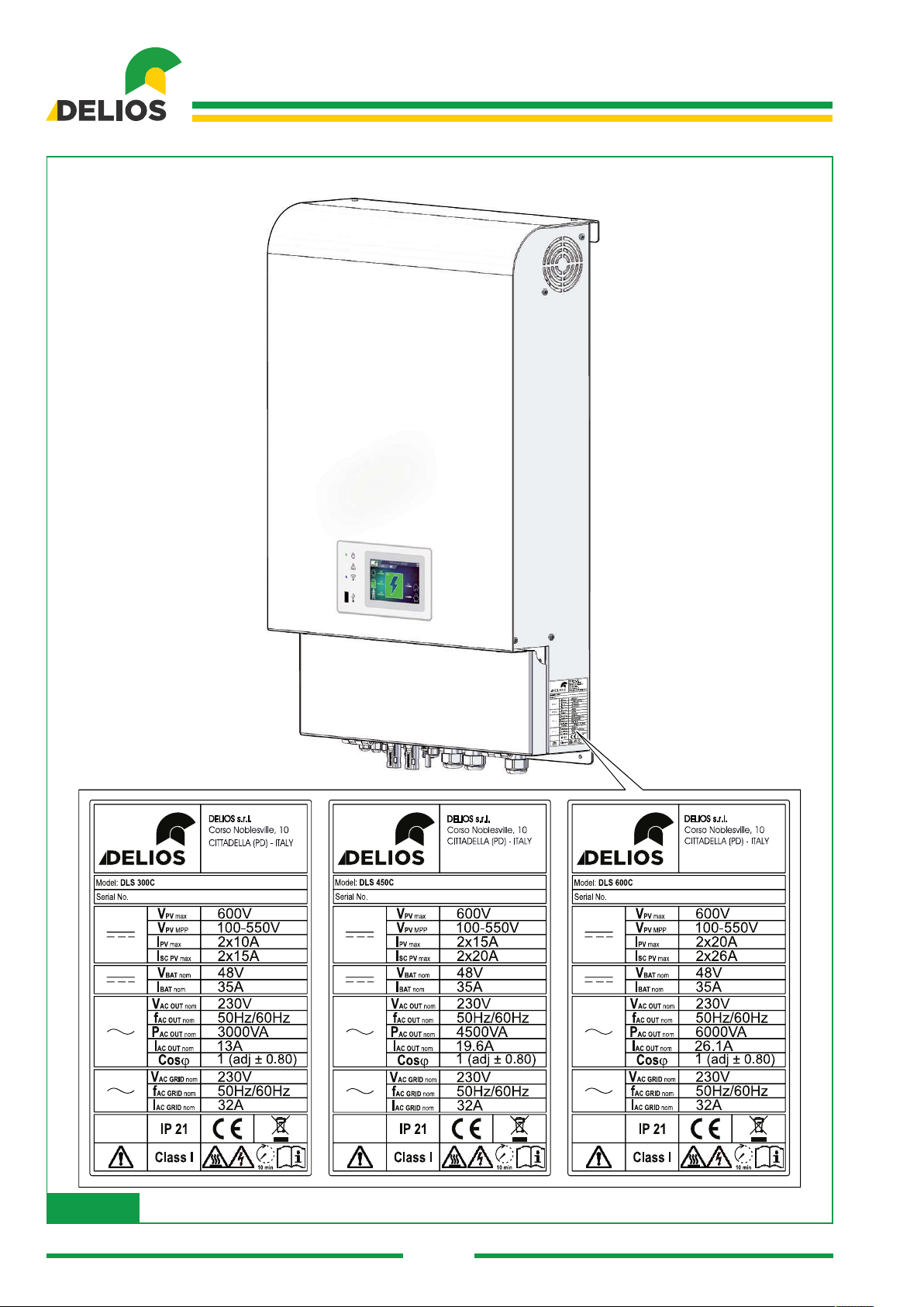
10 TECHNICAL DATA ........................................................................................................................55
10.1 Nameplate .............................................................................................................................55
10.2 Technical Features ................................................................................................................56
DLS 300C / 450C / 600C
17
Cod.: 240.010.0018
1 INTRODUCTION
1.1 Fields of Application
Thisinstallationmanualisintendedforqualiedinstallers.Themanualdescribeshowtosafelyinstall,con-
nect and start up the following DLS systems:
DLS 300C
DLS 450C
DLS 600C
1.2 Symbols Used in This Manual
Imminent dangers causing serious injuries. Danger of death.
Hazardous behaviours that could cause serious injuries.
Hazardous behaviours that could cause death.
Behaviours that could cause minor injuries to people or minor damages to things.
The notes preceded by this symbol relate to technical issues and ease operations.
Theseinstructionsareintendedforqualiedengineers.
1.3 Warranty
Warranty Conditions Provided by DLS
OurqualitycontrolprogramensuresthateachDLSproductismanufacturedexactlytospecicationsand
is subjected to exhaustive tests before leaving our factory.
Five Year Warranty
The warranty provided by DELIOS s.r.l. lasts for 5 years from the DSL system purchase date. The warranty
conditions are based on the EU Directive 99/44/EC, except for any statutory rights.
Extended Warranty
For all DLS systems, customers can purchase a 5 year extension of the manufacturers’ warranty, for a
maximum of 10 years. The warranty extension can only be purchased within 1 year from the DLS system
delivery date.
Warranty terms
Should DLS become faulty during the warranty period, one of the following services will be provided, at the
discretion of Customer Support Service (materials will be supplied for free, but labour costs will be charged):
RepairworkcarriedoutonDELOSs.r.l.premises
Repairworkcarriedoutontheinstallationsite
Replacingthedefectiveunitwithanewone(oroneofthesamevalueaccordingitsmodelandage)
Disclaimer

18
Cod.: 240.010.0018
DLS 300C / 450C / 600C
Disclaimer
Warranty claims and responsibilities for direct or indirect damages are excluded if caused by:
transportorstoragedamages
incorrectinstallationand/orcommissioning
modications,changesorattemptedrepairscarriedoutbyuntrainedandunauthorisedstaff
incorrectuseorinappropriateoperation
inadequatedeviceventilation
failuretocomplywithapplicablesafetystandards
forcemajeure(suchaslightening,overvoltages,storms,res)
aestheticimperfectionsnotaffectingthesystemoperation
damagescausedbyhumidityand/orotherenvironmentalconditions
The installer/retailer who installed the DLS must return the faulty system to DELIOS s.r.l. Customer Support
Service,whoreservestherighttoreplacetheunitwithanotherunitofequalorhighertechnicalspecica-
tions, at their own discretion.
Disclaimer
All rights related to the contents of this manual are owned by DELIOS s.r.l.. By using this manual, you ac-
cept the terms of this disclaimer clause. Every effort has been made by DELIOS s.r.l. to ensure the accu-
racy of this manual. However, DELIOS s.r.l. cannot accept responsibility for any errors or omissions in this
manual, nor for any damages caused by or associated with its use. No information published in this manual
can be copied or published in any way or by any means without prior written authorization by DELIOS s.r.l..
The information contained in this manual is subject to changes without notice, DELIOS s.r.l. does not have
any obligation to notify anything. After its publication, DELIOS s.r.l. does not have any obligation to update
or keep updating the information contained in this manual, and reserves the right to improve this manual
and/or the products described in this manual, at any time and without notice. We welcome your feedback
or advice if incorrect, misleading or incomplete information is found within the manual.
2 CAUTIONS
Theseinstructionsareprovidedforqualiedengineers.
Before carrying out any operations, make sure to have read and understood this manual.
Do not make changes and do not carry out maintenance operations not described in this manual.
The manufacturer does not accept responsibility for injuries to people and damages to things occurred
because the information within this manual has not been read and followed.
Theinstallationproceduremustbecarriedoutonlybyqualiedstaff.
Theoperationsdescribedhereinmustbecarriedoutonlybyqualiedengineers.
Thecustomeriscivillyliableforthequalicationsandmentalandphysicalconditionofmembersofstaff
who operate this equipment. They must always use personal protective equipment required by the legisla-
tion enforced in the destination country and anything else provided by their employer.
The DLS system can also operate without being connected to the mains (off-grid). In these conditions,
default factory setting requires the inverter output to be automatically connected to ground by an internal
device before starting the off-grid operation. However, should the factory setting need to be changed for
specicrequirements,theinverteroutputwillbeoating.
When exposed to the sun, PV panels can produce dangerous voltages. We recommend that the proce-
DLS 300C / 450C / 600C
19
Cod.: 240.010.0018
dures required to make the working area safe are carried out.
The DLS system can handle lead-acid and lithium 48V batteries. The batteries produce electricity and may
causeelectricshocksorresintheeventofashort-circuitorincorrectinstallation.
The batteries must be installed in a suitable area, compliant with local regulations. The installation area
mustprovideadequateventilationandbefreefromnakedamesandsparksastheycouldproducepoten-
tially explosive gases during the system operation.
Opening the DLS system, with the exceptions listed in this manual, is strictly prohibited.
Theequipmentmustnotbeinstalledbystaffwhoareunqualied,undertheinuenceofalcoholordrugs,
have prosthetic heart valves or pacemakers.
For any queries or problems during the system operation, even if not described herein, please contact
qualiedstaff.
TheDLSsystemcannotbemodiedinanyway.DELOSs.r.l.cannotacceptresponsibilityiftheDLSsys-
tem is incorrectly installed and shall not be liable for the equipment located upstream or downstream of the
system supplied.
Overriding the safety devices is extremely dangerous and will relieve the manufacturer from all responsibili-
ties for injuries to people and damages to things.
Arstaidkitmustbeprovided.Donotunderestimateburnsorwounds.
2.1 Operating Environment and Restrictions
Each system must only be used for operations it was designed for, by following the instructions and within
therangesspeciedinthenameplateand/orinthismanual,incompliancewithsafetynationalandinter-
national standards.
Anyusedifferentfromtheintendedusespeciedbythemanufacturerwillberegardedasentirelyinappro-
priate and dangerous and the manufacturer will therefore accept no responsibility.
This equipment is an integrated system able to convert direct current (DC), produced by a PV generator
and by a battery, to alternating current (AC) suitable for being used by local loads and/or fed to the national
grid.
Check the regulations applied by the electricity provider.
Check the solar panels manufacturer’s instructions.
Check the batteries manufacturer’s instructions.
Operating Range Limits:
The DLS system can be used only with PV systems which do not require one of the two poles to be ground-
ed.DLScanexclusivelybeusedwithVsystemscompliantwithClassAspecicrequirements,asstated
by standard IEC 61730.
Do not connect to PV1 and PV2 inputs any other energy source to the inverters in addition to the modules
mentioned above. The current leakage during normal operation must not exceed the limits stated in the
technicalspecications.
The DLS system can be connected, by using the BAT input, to a 48V lead-acid battery acting as a storage
device for the excess energy produced by the PV generator. The energy stored is then released into the
system, which will make it available to local loads, at the right and most appropriate time, in order to fully or
drastically reduce the energy drawn from the electricity grid.
The DLS system can be connected to the electricity grid only in the countries it is enabled for.

20
Cod.: 240.010.0018
DLS 300C / 450C / 600C
The DLS system canbeusedonlyifallthetechnicalspecicationsarecompliedwith.
Improper or unauthorised use:
Althoughourequipmentismanufacturedtothehigheststandards,allelectricalequipmentcancatchre.
The DLS system must be installed indoors.
The optimal operation of the DLS system is ensured at a maximum ambient temperature of 40°C (104°F).
The DLS system must be transported and stored in indoor locations with a temperature range of -30°C to
+70°C (-22°F to 158°F).
The DLS system must be used in locations with no acids, gases or other corrosive substances.
The DLS system must be used and stored in locations with relative humidity ranging from 5% to 95% with-
out condensation.
The DLS system must be transported in locations with a relative humidity ranging from 5% to 95%.
The DLS system must be used and stored in locations with atmospheric pressure ranging from 86kPa to
106kPa.
The DLS system must be transported in locations with atmospheric pressure ranging from 70kPa to 106kPa
The DLS system must be used at a maximum altitude above sea level of 3000m (9750 feet). For altitudes
higherthan2000m,becauseoftheairbeingmorerareed,specicconditionsmayarise,whichmustbe
taken into consideration when choosing the site of installation. All installations at altitudes higher than
2000m must be assessed case by case by taking into consideration the following critical issues:
lessefcientcooling:
reductionofairelectricalresistanceand,whenhighvoltagesarepresent,theformationofelectric
arcs:
presenceofcosmicradiations,whichmayaffectthecorrectoperationofelectroniccomponents.
2.2 Dismantling, Removal and Disposal
DELIOS s.r.l. DOES NOT accept responsibility for equipment disposal. The Customer must dispose of po-
tentially hazardous substances in compliance with regulations enforced in the country of installation and, in
any case, must avoid to cause any type of pollution.
The types of materials which make up the components of the equipment must be disposed of in suitable
rubbish tips.
Component disposal Construction materials
Frame, brackets, mountings Aluminium / Iron
Paint RAL
Electric cables Copper / Rubber
Electronic PCBs FR4 / Copper
This manual suits for next models
2
Table of contents
Other Delios Inverter manuals


Popular Inverter manuals by other brands


Sungrow
Sungrow SH3K6-30 user manual

Generac Power Systems
Generac Power Systems Guardian 005324-1 owner's manual

Fenner
Fenner QD:E Series Installation and operating instructions

Victron energy
Victron energy EasyPlus manual

Hitachi
Hitachi SJ-DN2 instruction manual

SEW-Eurodrive
SEW-Eurodrive MOVIDRIVE Series Interface manual


