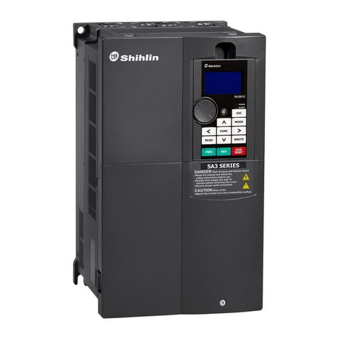
Shihlin SE2 Series User manual

1
Guide for Manual
Guide for Manual
The Shihlin electric SE2-TYPE inverters have been designed with many complex parameterized
functions to meet most of the application requirements from the market. For customers who contact
inverters for the first time, such a complex inverter may cause troubles when using it. So the users
are expected to read each part of this manual carefully so as to master the operating method of the
inverter. In case there is any question, please feel free to contact us.
In Chapter 2 of this manual, all the series and the corresponding specifications of Shihlin electric
SE2-TYPE inverters are listed in detail. Section 2-5 guids customers how to install the inverter and
emphasizes on precautions for safety that much attention should be paid to when utilizing the
inverter.
Chapter 3 guides customers how to use the inverter. In Section 3-1, the operating mode of the
inverter is outlined briefly; in Section 3-2, how to use the operation panel is described, and in
Section 3-3, simple operating steps are explained. Chapter 4 explains the functions of each parameter
in detail.
The definitions of terminologies in this manual are as follows:
1. Output frequency, target frequency, steady output frequency
• The actual output current frequency of the inverter is called ‘output frequency’.
• The frequency set by user (through a operation panel, multi-speed terminals, voltage signal or
current signal) is called ‘target frequency’.
• When the motor starts running, the output frequency of the inverter will gradually accelerate to the
target frequency, and finally run steadily at the target frequency. The output frequency at this time
is called ‘steady output frequency’.
2. There are detailed instructions on parameter settings in Chapter 4. In case users are not familiar
with these settings, arbitrary adjustment of the parameter may result in abnormal operations. All
parameters can be reset to their default values by the parameter of P.998. For the setting
procedure of this parameter, please refer to P.998 in Chapter 4.
3. The ‘operation mode’ of inverter, and the ‘working mode’of the operation panel:
The operating mode determines the reference source for the target frequency and the signal source
for starting. The Shihlin inverter has totally 9 operating modes. Please refer to Section 3-1 for
details.
The operation panel mainly concerns monitoring of numeric values, setting of parameters and
setting of target frequency. The Shihlin operation panel has totally 5 working modes. Please refer
to Section 3-2 for details.
4. The difference between ‘terminal name’and ‘function name’:
Near the terminals of the control board or the main board, printed letters can be found. These
letters are used to distinguish each terminal, and thus called ‘terminal name’.
For ‘multi-function control terminal’ and ‘multi-function output terminal’, besides the terminal
name, the ‘function name’ is also necessary to be defined. The function name indicates the actual
functions of the terminal.

2
Guide for Manual
Guide for Manual
When explaining the function for a terminal, the name used is its ‘function name’.
5. The difference between ‘on’and ‘turn on’:
When explaining the function for the ‘multi-function control terminal’, two words ‘on’and ‘turn
on’are often used.
The ‘on’is used to indicate that the external switch of the terminal is in close state, and thus
belongs to the description of the state.
The ‘turn on’is employed to describe the action that the external switch of the terminal is shut on
from the open state to the close state, and thus belongs to the description of action.
6.All the ‘P.’s mentioned in this manual mean ‘parameter’.

3
Contents
1. Product Examination................................................................................................... 4
2. Introduction of Shihlin Inverter.................................................................................. 5
3. Primary operation...................................................................................................... 31
4. Parameter description ............................................................................................... 43
5. Inspection and Maintenance ................................................................................... 125
Appendix 1 Parameter list........................................................................................... 128
Appendix 2 Alarm Code List...................................................................................... 139
Appendix 3 Warning code list..................................................................................... 142
Appendix 4 Troubles and Solutions............................................................................ 143
Appendix 5 Optional equipment................................................................................. 144
Appendix 6 Frequency parameters of ultra-high-speed ............................................. 152

4
1. Product Examination
Product Examination
Each SE2-TYPE inverter has been checked strictly before delivery and packed carefully to prevent
from mechanical damage. Please check as follows after opening the package.
• Please check whether it is damaged during transport.
• Please check whether the inverter type is identical with which shown on the package.
1.1 Nameplate instruction:
FREQ. Range : 0.2~1000Hz
EC00001
MFG. NO. : L2L0072
Serial NO. :
Style No. :
SE2-021-0.75K-DL
Input : 14A 3PH AC380~480V 50/60Hz
Output : 13A MAX 3PH AC380~480V 5.5KW
1.2 Type instruction:
Product series
SE2 - 021
-0.75K
Suitable motor: 0.4K=0.4KW;
- DL
Input voltage: 021: 220V 1-PHASE
023: 220V 3-PHASE
043: 440V 3-PHASE
0.75K=0.75KW……
None: without DU03 operation panel
D: with DU03 operation panel
None: without build-in filter
L: with build-in filter
1.3 Indent symbol instruction:
For example:
Demand Indent symbol
Specification
Operation
panel
Build-in
filter
SE2-021-0.4K(SE2 Series Single-Phase 220V 0.5HP
)
Yes Yes
SNKSE
20210R2KDL
SE2-023-1.5K(SE2 Series Three-Phase 220V 2HP)Yes No SNKSE20231R5KD
SE2-043-2.2K(SE2 Series Three-Phase 440V 3HP)No Yes SNKSE20432R2KL
SE2-043-3.7K(SE2 Series Three-Phase 440V 5HP)No No SNKSE20433R7K

5
2. Introduction of Shihlin Inverter
Introduction of Inverter
2.1 Electric specification
2.1.1 220V Series Single-Phase
Model SE2-021-□□□K 0.4K 0.75K 1.5K 2.2K
applicable motor capacity
HP 0.5 1 2 3
kW 0.4 0.75 1.5 2.2
Output
Rated output capacity kVA (Note) 1.2 1.9 3.0 4.2
Rated output current A (Note) 3.0 5.0 8.0 11.0
Over-current capability
150% 60 seconds; 200% 1 second (reverse time
characteristics)
Maximum output voltage 3 Phase 200~240VAC
Power
supply
Rated power voltage single phase 200~240V 50Hz / 60Hz
Power voltage permissible
fluctuation
single phase 180~264V 50Hz / 60Hz
Power frequency permissible
fluctuation
±5%
Power source capacity kVA 1.8 3 4.5 6.4
Cooling method Nature cooling
Forced air cooling
Weight kg 1.2 1.2 1.9 1.9
2.1.2 220V Series Three-Phase
Model SE2-023-□□□K 0.4K 0.75K 1.5K 2.2K 3.7K 5.5K 7.5K
applicable motor
capacity
HP 0.5 1 2 3 5 7 10
kW 0.4 0.75 1.5 2.2 3.7 5.5 7.5
Output
Rated output capacity kVA (Note) 1.2 1.9 3.0 4.2 6.7 9.2 12.6
Rated output current A (Note) 3.0 5.0 8.0 11.0 17.5 24 33
Over-current capability
150% 60 seconds; 200% 1 second (reverse time
characteristics)
Maximum output voltage 3 Phase 200~240VAC
Power
supply
Rated power voltage 3 Phase 200~240V 50Hz / 60Hz
Power voltage permissible
fluctuation
3 Phase 170~264V 50Hz / 60Hz
Power frequency permissible
fluctuation
±5%
Power source capacity kVA 1.8 3 4.5 6.4 10 13.8 19
Cooling method
Nature
cooling
Forced air cooling
Weight kg 1.2 1.2 1.2 1.9 1.9 3.8 3.8

6
2.Introduction of Shihlin Inverter
Introduction of Inverter
2.1.3 440V Series Three-Phase
Model SE2-043-□□□K 0.4K 0.75K
1.5K 2.2K 3.7K 5.5K 7.5K 11K
applicable motor capacity
HP 0.5 1 2 3 5 7 10 15
kW 0.4 0.75 1.5 2.2 3.7 5.5 7.5 11
Output
Rated output capacity kVA
(Note)
1.2 2.0 3.2 4.6 6.9 9.2 13 18
Rated output current A (Note) 1.5 2.6 4.2 6.0 9.0 12 17 23
Over-current capability
150% 60 Seconds; 200% 1 Second (reverse time
characteristics)
Maximum output voltage 3 Phase 380~480V
Power
supply
Rated power voltage 3 Phase 380~480V 50Hz / 60Hz
Power voltage permissible
fluctuation
323~506V 50Hz / 60Hz
Power frequency permissible
fluctuation
±5%
Power source capacity kVA 1.8 3 4.8 6.9 10.4 13.8 19.5 27
Cooling method
Nature
cooling
Forced air cooling
Weight kg 1.2 1.2 1.2 1.9 1.9 3.8 3.8 3.8

7
2.Introduction of Shihlin Inverter
Introduction of Inverter
2.2 Common specification (Inverter characteristics)
Control method
SVPWM control, V/F control, facility vector control, Speed sensorless
vector control.
Output frequency range
0.2~1000Hz (The starting frequency setting range is 0~600Hz). Please
refer to P.187 in Chapter 4.
Resolution for
setting frequency
Digital
setting
When P.187=0, if the frequency set value is below 100Hz, the resolution
will be 0.01Hz. If
the frequency set value is above 100Hz, the resolution
will be 0.1Hz. When P.187=1, the resolution of frequency will be 0.1Hz.
Analog
setting
When setting DC 0~5V signals, the resolution will be 1/500;
When setting DC 0~10V or 4~20mA signals, the resolution will be
1/1000.
Output frequency accuracy 0.01Hz
Voltage / frequency output
characteristics
Base voltage (P.19), base frequency (P.3) can be arbitrarily set.
Constant torque model, variable torque model can be selected (P.14).
Start torque 150% (1Hz): when use the facility vector control.
Torque boost
The torque boost setting range is 0~30% (P.0), auto boost, slip
compensation.
Acceleration/deceleration
curve characteristics
The acceleration/deceleration time (P.7, P.8), resolution:0.01s/0.1s,
switch by P.21. The setting range is 0.01~360s or 0.1~3600s for
selection. Different ‘acceleration/deceleration curve’ model can be
selected (P.29).
DC braking
The DC braking action frequency is 0~1000Hz (P.10); the DC braking
time is 0~60 Seconds (P.
11); and the DC braking voltage is 0~30%
(P.12). Linear braking and Idling braking selection (P.71).
Stalling protection The stalling protection level can be set to 0~400% (P.22).
Target frequency setting
Operation panel setting, DC 0~5V signal setting, DC 0~10V signal
setting, DC 4~20mA signal setting, 2 voltage input
or one voltage and
one current input to select. Multi-
speed stage levels setting,
Communication setting.
PID control Please refer to P.170~P.183 in Chapter 4.
Multi-function control
terminals
Motor starting (STF, STR), the second function (RT), ‘16-speed
operation’(RL, RM, RH, REX), external thermal relay (OH), reset
(RES), etc. (can be set by the user (P.80~P.84, P.86))
Multi-functi
on output
terminals
Multi-function
output
terminals (SO,
SE)
P.40 Inverter running (RUN), output frequency detection (FU),
Up to
frequency (SU), overload detection (OL), zero current detection
(OMD), alarm (ALARM), Section detection
(PO1), Periodical
detection (PO2), and Pause detection (PO3), Inverter output (BP),
Commercial power-supply output (GP).
Multi-function
output relay
P.85
Multi function
analogy meter
Multi-function DC (0~10V)(AM)
output: output frequency, output current (P.54).

8
2.Introduction of Shihlin Inverter
Introduction of Inverter
Operation panel
Running status
monitoring
Output frequency monitoring, output current monitoring, and
output voltage monitoring.
HELP mode
Alarm history monitoring, alarm history clear, all parameters clear,
and soft version read.
LED indication
lamp(6)
Run indication lamp, frequency monitoring indication lamp,
voltage monitoring indication lamp
, current monitoring indication
lamp, mode switching indication lamp, and
PU/external terminals
control indication lamp.
C
ommunication
function
RS485 Internal RS485 communication.
Optional
function
Optional function:
Terminal
block
communications expansion board,
RJ11, RJ-45, Profibus, DeviceNet Terminal block
communication
expansion board.
Protection mechanism
/ Alarm function
Output short circuit protection,Over-current protection, P-N
over-voltage protection, voltage too low protection, motor over h
eat
protection (P.9), IGBT module over heat protection, braking
transistor abnormality protection, communication abnormality
protection, etc.
Environmental
condition
Ambient
temperature
-10 ~ +50℃(non-freezing)
Ambient
humidity
Below 90%Rh (non-condensing)
Storage
temperature
-20 ~ +65℃
Environment
around
In room, no corrosive gas, no flammable gas, no flammable dust
Altitude and
vibration
Below 1000 meters, below 5.9m/s2 (0.6G).
Certification Meet the requirements of CE certification standards (the –DL type).
Note: 1.If several multi-function output relays are needed, you can choose the I/O expansion board, on which there
are 2 multi-function output relays. For detailed instruction, please refer to appendix 5.
2. Communications expansion board option details, please refer to Appendix 5.
3. Profibus is the registered trademark of Profibus international.
4. DeviceNet is the registered trademark of ODVA (Open Device Vendor Association).

9
2.Introduction of Shihlin Inverter
Introduction of Inverter
2.3 Mechanical Dimensions
2.3.1 Form
2.3.2 Dimension
Model
D(mm)
W(mm)
H(mm)
A(mm)
B(mm)
C(mm)
SE2-021-0.4K
148
85
148
75
138
Φ 5
SE2-021-0.75K
148
85
148
75
138
Φ 5
SE2-021-1.5K
186
100
157
90
176
Φ 5
SE2-021-2.2K
186
100
157
90
176
Φ 5
SE2-023-0.4K
148
85
148
75
138
Φ 5
SE2-023-0.75K
148
85
148
75
138
Φ 5
SE2-023-1.5K
148
85
148
75
138
Φ 5
SE2-023-2.2K
186
100
157
90
176
Φ 5
SE2-023-3.7K
186
100
157
90
176
Φ 5
SE2-023-5.5K
266
141
201.5
126
244
Φ 6
SE2-023-7.5K
266
141
201.5
126
244
Φ 6
SE2-043-0.4K
148
85
148
75
138
Φ 5
SE2-043-0.75K
148
85
148
75
138
Φ 5
SE2-043-1.5K
148
85
148
75
138
Φ 5
SE2-043-2.2K
186
100
157
90
176
Φ 5
SE2-043-3.7K
186
100
157
90
176
Φ 5
SE2-043-5.5K
266
141
201.5
126
244
Φ 6
SE2-043-7.5K
266
141
201.5
126
244
Φ 6
SE2-043-11K
266
141
201.5
126
244
Φ 6

10
2.Introduction of Shihlin Inverter
Introduction of Inverter
2.4 Name of each part
2.4.1 Nameplate and model
FREQ. Range : 0.2~
1000
Hz
EC00001
MFG. NO. : L2L0072
Serial NO. :
Style No. :
SE2-021-0.75K-DL
Input : 14A 3PH AC380~480V 50/60Hz
Output : 13A MAX 3PH AC380~480V 5.5KW
2.4.2 SE2-0XX-0.4K~11K (0.5HP~15HP)
When wiring, the wire must go through the ‘wiring outlet’before connecting with the terminal bank.

11
2.Introduction of Shihlin Inverter
Introduction of Inverter
Note: 1. The enlarge figure of the control-circuit terminal block nameplate is as follows:
2. There’s no screw for the 1-Phase type.

12
2.Introduction of Shihlin Inverter
Introduction of Inverter
2.5 Installation and wiring
2.5.1 Transport
Handling must take the fuselage, not only take cover or any part of the inverter, or it may drop out
then cause dangerous.
2.5.2 Stockpile
This product before installing must be placed in the packaging, if not use, in order to change the
frequency which can meet the company's warranty scope and future maintenance, must pay attention
to the following matters when storage:
1. Must be placed without dirt, dry place.
2. The environment temperature must be stored position in -20℃to +65℃.
3. Storage location relative humidity must from 0% to 95% range, and no condensation.
4. Avoid stored in contains corrosion gas, liquid environment.
5. The best suitable packing on shelves or mesa.
Note: 1.If meet the standard requirements, s
uch as humidity temperature changes also occurred hurriedly
condensation and icy may occur in this place, should be avoided.
2. Don't directly on the ground, also should be on appropriate shelves, and if the bad surroundings, it should
be placed in the bag of desiccant.
3. If the custody period
more than 3 months, the ambient temperature requirements shall not be higher than
30 degrees. It is to consider the electrolytic capacitors no electricity deposited, when high temperature, the
characteristic easy degradation.
4. Inverter installed in the control device or the plate when not used (in construction which especially the
extra humid and dust), inverter should been
remove, move put in accordance with the above mentioned
storage conditions appropriate environments.
5. The electrolytic capacitors is long-term no electricity, the characteristic easy degradation. Do not place in
the no state electricity more than one year.
2.5.3 EMC Installation instructions
Inverter is the same as other electrical and electronic equipment, when working in a power system, it
is the electromagnetic interference sources, and also is the electromagnetic receiver. The working
principle of inverter determines that it will produce certain electromagnetic interference and noise, in
order to guarantee the inverter to the electromagnetic environment in certain work, in designed, it
must have a certain interference of electromagnetic interference ability. In order to make the drive
system can normal operation, and meet the challenge which CE declared, please meet the following
several aspects in installation:
1. Field wiring
Power line from power transformer independent power supply, generally uses five core or four core,
forbidden neutral and ground share a thread.

13
2.Introduction of Shihlin Inverter
Introduction of Inverter
Commonly signal wire (weak) and power lines (heavy) are in control cabinet, to inverterr, electric
line of force divided into incoming lines and tail wire. In wiring, signal wire and power lines should
distributed in different regions, in close (within 20cm), parallel lines and interlace lines are
unallowed strictly, and the two cannot be tied together. If the signal cable must pass through between
power lines, the two should maintain a 90 degree Angle. The parallel lines and interlace lines which
of power line can not crisscross wiring or be tied together, especially in occasions which noise filter
installed, it will make coupled noise when the electromagnetic noise through the distributed
capacitance, thus noise filter will out of action.
Generally the same controller with different electric equipment, such as inverter, filter, PLC,
measurement instrument, its transmitter electromagnetic noise to external and bear ability each are
not identical, this requires to classify these equipments, the classification can be divided into strong
noise quipment, and noise sensitive equipment, the similar equipmentmust be installation in the same
area, inhomogeneity equipment must be keep distance more than 20cm.
2. Input noise filter, input and output magnet ring (zero phase reactor)
Increase noise filter in the input terminal, which will isolate the inverter and the other equipment can
effectively reduce the conduction and radiation ability. Install the input reactor this synopsis
recommendation, can satisfy the limits value of conduction and radiation which CE declared. In the
input and output terminal increased the ferrite lateral auxiliary will be better effect.
3. Shield
Good shielding and grounding can greatly reduce the interference of inverter, and can improve the
anti-interference ability of the inverter. Using the good conduct electricity sheet metal sealing, and let
the sheet metal grounding, can satisfy the limits value of radiation which CE declared.
4. Grounding
Inverter at work must be safe and reliable grounding. Grounding is not only for equipment and safety,
but also is the simplest, the most efficient and the lowest cost method to solving the EMC problem,
should be prioritized. Please refer to the "terminal wiring" section.
5. Carrie Wave
The leakage current contains the leakage current from line to line or over the ground. It depends on
the size of the capacitance and the carrier frequency of the wiring system. The carrier frequency is
higher, the motor cable is longer, the cable cross-sectional area is larger, and the leakage current is
larger too. Reduce the carrier frequency can effectively reduce the leakage current, when a long line
of motor (50m above), the output side should be installed ac reactor or sine wave filter, when the
motor line is longer, every distance should to install a reactor.At the same time, reduce carrier
frequency can effectively reduce the conduction and radiation interference, in 2K carrier frequency,
can satisfy the limits value of the conduction and radiation which CE declared.

14
2.Introduction of Shihlin Inverter
Introduction of Inverter
2.5.4 Installation notice
1. Please install in an upright direction
2. Proper clearance shall be kept from surroundings
when installing
3. The ambient temperature shall not exceed the
permissible value.
4. Correct position for installing in a protection
cabin.
Ventilating funt
5. Please do not install the inverter on a surface of inflammable material such as wood etc.
6. Please do not install the inverter at places exposed to explosive gas, inflammable dust.
7. Please do not install the inverter at places with airborne oil mist and dust.
8. Please do not install the inverter at places exposed to corrosive gas, salt laden air.
9. Please do not install the inverter in the environment of high temperature and high humidity.
Note: 1.Only qualified electrical professional personnel can carry out the installation, wire arrangement,
dismounting and maintenance.
2. Please ensure to comply with the installation notice. In case the installation notice has not been fully
complied with and damage of the inverter or dangerous accidence thus be resulted in, our company will
not undertake any legal responsibility. In case there is any question when installing, please feel free to
contact us.

15
2.Introduction of Shihlin Inverter
Introduction of Inverter
2.5.5 System wire arrangement of SE2-0XX-0.4K~11K (0.5HP~15HP) series
FUSE/NFB
Magnetic contactor
Input AC Line Reactor
Zero-phase Reactor
Output AC Line Reactor
EMI filter
R/L1 S/L2 T/L3
U/T1 V/T2 W/T3
Motor
B
R
P
PR
Braking resistor
B
U
E
B
R
Braking unit
Power
Power
supply
Please follow the specific
power supply requirement
shown in this manual.
Fuse/NFB
There may be an inrush
current during power up.
Please refer to 2.7.1 and
select the correct fuse /NFB.
Magnetic
contactor
Please do not use a Magnetic
contactor as the I/O switch of
the AC motor drive, as it will
reduce the operating life cycle
of the AC drive.
Input AC
Line Reactor
AC line reactor should be
installed to improve the input
power factor. The wiring
distance should be less than
10m. Please refer to 2.7.6.
Zero-phase
Reactor
Zero-phase reactors are used to
reduce radio noise especially
when audio equipment installed
near the inverter. Effective for
noise reduction on both the
input and output sides.
Attenuation quality is good for a
wide range from AM band to
10Mhz. Please refer to 2.7.5.
EMI filter Used to reduce electromagnetic
interference.
Braking unit Used to reduce stopping time of
the motor.
Output AC
Line Reactor
Motor surge voltage
amplitudes depending on
motor cable length. The output
AC line reactor is necessary to
install on the inverter output
side. Please refer to 2.7.6.

16
2.Introduction of Shihlin Inverter
Introduction of Inverter
2.5.6Terminal wire arrangement of SE2-0XX-0.4K~11K(0.5HP~15HP)series
===== Note: ==============================================================
1. In the above figure, Main circuit and control circuit wiring or ground wiring should be noted that
the thickness of wire.
2. For the usage of external thermal relay, please refer to P.80~P.84, P.86 in Chapter 4.
3. Make sure do not to short PC and SD.
4. In the above figure, Dotted line metal, please refer 2.5.7
5.The SE2-TYPE inverter have internal RS485 communication, and also can uses pluggable
communications expansion boards CB01, CB02, CB03, PD01, DN01; For detailed instructions,
please refer to appendix 5.
=======================================================================

17
2.Introduction of Shihlin Inverter
Introduction of Inverter
Note: 1. For the multi-function control terminals, please refer to P.80~P.84, P.86, and for the multi-function output
terminals, please refer to P.40 in Chapter 4.
2. For SE2-0XX-0.4K~11K (0.5HP~15HP) series, the multi-function control terminals have both the ‘Sink
Input’ mode and the ‘Source Input’ mode. There is a Jumper that can be used to alternate between those
two modes. If the Jumper
is on the left side, ‘Sink Input’ mode is chosen, and ‘Source Input’ mode is
chosen while on the right side. Shown as follows:
Sink Input Source Input
No matter what kind of multi-function control terminal it is, all of its outside wire arrangement can be
considered as a simple switch. If the switch is ‘on’, the control signal will be put into the terminal, if the
switch is ‘off’, the control signal is shut off.
If ‘Sink Input’ mode is selected, the function of the terminal is active when it is shorted with SD or
connected with the external PLC. In this mode, the current flows out of the corresponding terminal
when it is ‘on’
. Terminal SD is common to the contact input signals. When using an external power
supply for transistor, please use terminal PC as a common to prevent misoperation caused by leakage
current.
STF
STR
SD
Inverter
Sink Input: the multi-function control
terminal is shorted directly with SD Sink Input: the multi-function control terminal
is connected directly with open-collector PLC
PLC
I
I
DC
24V
PC
STF
STR
SD
Inverter
DC
24V
PC
Sink Input: the multi-function control terminal is connected
with open-collector PLC and external power supply
PLC
I
STF
STR
SD
Inverter
DC
24V
PC
DC
24V

18
2.Introduction of Shihlin Inverter
Introduction of Inverter
If ‘Source Input’mode is selected, the function of the multi-function control; terminal is active when it is
shorted with PC or connected with the external PLC. In this mode, the current flows into the
corresponding terminal when it is ‘on’. Terminal PC is common to the contact input signals. When using
an external power supply for transistor output, please use terminal SD as a common to prevent
misoperation caused by leakage current.
STF
STR
PC
Inverter
Source Input: the multi-function control
terminal is shorted directly with PC Source Input: the multi-function control terminal
is connected directly with open-emitter PLC
PLC
II
DC
24V
SD
STF
STR
PC
Inverter
DC
24V
SD
Source Input:
the multi-function control terminal is
connected with open-emitter PLC and external power supply
PLC
I
STF
STR
PC
Inverter
DC
24V
SD
DC
24V
Main-circuit terminals
Terminal name Remarks
R/L1- S/L2- T/L3
Connect to the commercial power supply.
U/T1-V/T2-W/T3
Connect to three-phase squirrel-cage motor.
P- PR Connect to brake resistors. (Note1, 2)
P- N Connect to brake unit. (Note3)
The grounding terminal for the case of the inverter. For 220V series, the third type
of grounding shall be adopted. For 440V series, special type of grounding shall be
adopted. (Note 4)

19
2.Introduction of Shihlin Inverter
Introduction of Inverter
Note: 1. For SE2-0XX-0.4K~11K (0.5HP~15HP) series of inverters, the brake resistor isn’t appended when sales.
2. For the related knowledge on regenerative voltage, please refer to P.30 in Chapter 4.
3. P and N are the positive and negative terminals of the internal DC voltage of the inverter. In order to
strengthen the braking capability during deceleration, it is suggested to purchase the option of ‘brake unit’
which is mounted between the terminals P and N. The ‘brake unit’ can effectively dissipate the feedback
energy from the motor to the inverter when decelerating. In case there is any problem on purchasing of
the ‘brake unit’, please feel free to contact us.
4. For safety and reduce noise, grounding terminals of inverter must to be good grounded. To avoid electric
shocks and fire accident, external metal wire of electrical equipment should be short and thick and it
should be connected to the special grounding terminals of inverter. If many of the inverters are placed
together, all inverters must be connected to the common ground. Please refer to the following picture
and
determine not formed circuit between grounding terminal.
Best
Average
Poor

20
2.Introduction of Shihlin Inverter
Introduction of Inverter
Control terminals
Terminal type
Terminal
name
Function
name
Remarks and function description
On-off signal
input
STF Optional
These terminals are multi-function control terminals
(SINK/SOURCE mode switchable).
For detailed descriptions, please refer to P.80~P.84, P.86
in
Chapter 4.
STR Optional
M0 Optional
M1 Optional
M2 Optional
RES Optional
SD SD
Common reference Ground for STF, STR, M0, M1, M2 and
RES
PC PC
In the ‘Source input’ mode, it provides a common power
supply for the terminals referred above.
Analog signal
input
10 --- The internal power is DC 10V at this terminal.
2 ---
The input point of voltage signal 0~5V or
0~10V, is used to set the target frequency.
P.38
4 ---
The input point of voltage signal 0~5V or
0~10V/
input points of current signal
4mA~20mA (switch with P.17)
, is used to set
the target frequency. (Note 1)
P.39
5 --- The common reference ground of 2, 4, 10 and AM.
Relay output
A --- Normally, points A-C are always ‘open-circuit’, and
points
B-C are always ‘short-circuit’.Contact capacity is
VDC30V /
VAC230V-0.3A
B ---
C ---
Open collector
output
SO Optional
The terminal can also be called ‘multi-function output
terminal’. The function name can be set by P.
40. For detailed
description, please refer to P.40 in Chapter 4.
SE SE Open collector output reference ground.
Analog signal
output AM ---
Connected with an external analog meter to indicate the
output frequency or current. Contact capacity is 0~10VDC/2mA
.
Please refer to P.54,P.55, P.56, P.191,and P.192 in Chapter 4.
Communication
terminal
DA+ DA+ RS485 serial communication terminal
DB- DB-
Dedicated
terminals
WF WF
Do not the connection during normal operation, may cause a
malfunction.
This manual suits for next models
19
Table of contents
Other Shihlin Inverter manuals
Popular Inverter manuals by other brands
Growing
Growing GRENGINE Ultralite user manual
Valleylab
Valleylab Force EZ - C Series Service manual
dolycon
dolycon CT100G Series manual

Mitsubishi Electric
Mitsubishi Electric FR-LU08 instruction manual

Somogyi Elektronic
Somogyi Elektronic Home MX 202 instruction manual
CHINT
CHINT NVF5 Series Quick Start-Up Wizard
