Risen RSM60-6- BMDG Series Manual

RISEN ENERGY CO., LTD. (DOCUMENT)
INSTALLATION AND MAINTENANCE
MANUAL
OF BIFACIAL MODULE PRODUCTS
DOCUMENT NO.
RS/03-MTP-016-2019
COMPILER
Pei shichao
EDITION
A/3[2019]
REVIEWER
Zhang shengcheng
DISTRIBUTION NO.
APPROVER
Liu yafeng
STATUS
STAMP
THIS DOCUMENT HAS A TOTAL OF *35* PAGES INCLUDING THE FRONT COVER
ISSUE DATE 2019-05-30 .IMPLEMENTATION DATE 2019-05-30
2020 .
【
10G
】

2
RS/03-GT-016-2019 日期:2020-3-9
DESCRIPTION OF AMENDMENT
D AT E
EDITION
CHAPTER
AMENDED CONTENTS
RECORDER
2018.04
A/0
Full Text
Installation manual instructions
Chen Shuilin
2018.11 A/0 Chapter 8
Add module specifications, update the
content
Bai Wenkai
2019.01 A/0 Full Text Updates the content Liu Fengmin
2019.02 A/1 Chapter 8
Add bolting method for bifacial dual-
Glass modules
Chen Shuilin
2019.04 A/1 Chapter 8
Add 158.75 Cell module type; Update
mounting hole position
Chen Shuilin
2019.06 A/2
Chapter 2,
8,11
Add Added heterojunction module type,
update the content
Chen Shuilin
2020.03 A/3 Chapter 2, 8
Add RSMxxx-8 PV module model,Update the
installation diagram, add the flat single shaft
installation method, and delete some
installation methods
Pei Shichao
REQUIREMENTS: THIS DOCUMENT SHALL BE REVIEWED AND EVALUATED BY LEADING DEPARTMENT AT
LEAST ONCE A YEAR, AND UPDATES SHALL BE MADETO ENSURE THE PRACTICABILITY OF THE
DOCUMENT WHEN IT IS NECCESARY.
DOCUMENT COUNTERSIGN
DEPARTMENT
NAME
Quality and
global customer
service
Technical
compliance
Global customer
service
Components R
& D center
COUNTERS
IGNER
Hu yuhui
Song
Yifeng
Chen
Xiaoxu
Liu yafeng

3
RS/03-GT-016-2019 日期:2020-3-9
一、PURPOSE
This manual provides relevant information on the installation and safe use of PV modules produced
by Risen Energy Co., Ltd and Risen Energy (CHANGZHOU) Co., Ltd. (hereinafter referred to as Risen
Energy or Risen), and recommends safe and reliable module installation and maintenance instructions for
our customers.
Before installation, the installer must read and understand this manual. If you have any questions,
please contact sales or customer service staff of Risen for further understanding. When installing, the
installer shall comply with all safety precautions and installation laws and regulations in this manual. The
installation personnel should be familiar with the mechanical load and electrical requirements of the
installation system, and Risen has the right to refuse to compensate for the damage of the modules
caused by the operation reasons or design defects of the power generation system.
二、SCOPE
This document is applicable to the installation of bifacial modules of Risen Energy Co., Ltd. (including all
factories).
三、OBLIGATIONS
Module Technology Department: responsible for the preparation, update and maintenance of this
document.
四、REFERENCES
NO
五、DEFINITIONS
NO
六、PROCEDURE
NO
七、RELEVANT RECORDS AND SHEETS
See document resume
八、SUPPLEMENTARY PROVISIONS
The technology department reserve the final right to interpret this document. If there is no controlled
seal on the document or any part of it is missing, this document will be invalid. Something that violate the
management of documents is prohibited for any department or individual, such as printing, copying, and
duplicating the document. If there is any discrepancy caused by translation, the Chinese version shall
prevail.

4
RS/03-GT-016-2019 日期:2020-3-9
CATALOG
1. Manual Introduction......................................................................................................................................... 5
2. Applicable Products ........................................................................................................................................ 5
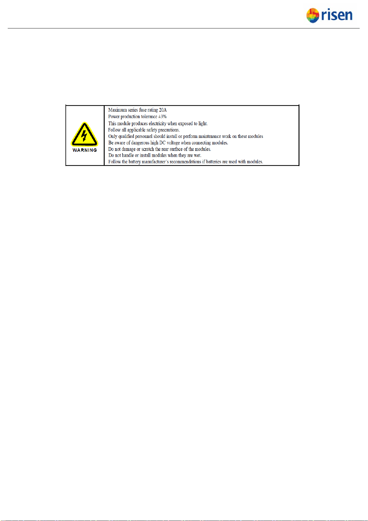
3. Warning ............................................................................................................................................................. 6
4. Safety Cautions................................................................................................................................................ 6
5. Unloading, Transportation and Storage ..................................................................................................... 10
5.1. Markers on outer packaging..................................................................................................................... 10
5.2. Unloading cautions .................................................................................................................................... 10
5.3. Secondary transportation and Warning.................................................................................................. 11
5.4. Storage ........................................................................................................................................................ 12
5.5. Markings on module .................................................................................................................................. 13
6. Unpacking....................................................................................................................................................... 13
7. Installation....................................................................................................................................................... 14
7.1. Environment conditions and site selection............................................................................................. 14
7.2. Tilt angle of Installation.............................................................................................................................. 15
7.3. Installation requirements for bi-facial dual glass module..................................................................... 16
8. Installation Guidelines................................................................................................................................... 17
8.1. Bolting method for framed Bi-facial dual glass module........................................................................ 18
8.2. Clamping Method....................................................................................................................................... 21
8.3. Tracking system ......................................................................................................................................... 23
9. Cable layout.................................................................................................................................................... 25
10. Electrical Connection .................................................................................................................................... 26
10.1. Bypass secondary .................................................................................................................................. 29
10.2. Grounding ................................................................................................................................................ 30
10.3. Inspection and Maintenance................................................................................................................. 31
11. Electrical Parameters……………………………………………………………………………………….
12. Module visual inspection and replacement ............................................................................................... 32
12.1. Cleaning................................................................................................................................................... 33
12.2. Troubleshooting ...................................................................................................................................... 34
13. DISCLAIMER ................................................................................................................................................. 35

5
RS/03-GT-016-2019 日期:2020-3-9
1. Manual Introduction
Thanks for choosing Solar PV modules from Risen Energy Co., Ltd (hereinafter called Risen).
In order to ensure that the PV modules are installed correctly, please read the following installation manual
carefully before modules are installed and used.
Please let the well trained professional to engage the PV module’s installation, running and maintenance
due to these works are based on the professional knowledge. The personnel for the installation should be
familiar with the mechanical and electrical requirements.
Please get contact with Risen After Service Department (Afterservice@risenenergy.com) or Risen local
agency if you want to get more details or there is any question.
2. Applicable Products
Risen’s photovoltaic solar module is a DC power supply, which has the character of high reliability and
nearly no-maintenance. It can be used in power systems of remote areas, home power systems,
renewable energy vehicles, hydropower stations, water pumps, communication system or constitute solar
photovoltaic power station directly. These systems not only can be used by battery, but also can be used
by grid-connection directly without battery.
This document is applicable to the following PV Solar Modules types:
Bifacial module
RSM60-6-xxx BMDG RSM72-6-xxx BMDG RSM120-6-xxx BMDG RSM144-6-xxxBMDG
(M2、G1)
RSM132-6-xxx BMDG RSM156-6-xxx BMDG RSM120-7-xxxBMDG RSM144-7-xxxBMDG
RSM156-7-xxxBMDG RSM150-8-xxxBMDG
HIT- Bifacial
module
RSM60-6-xxx BHDG RSM72-6-xxx BHDG RSM120-6-xxx BHDG RSM144-6-xxx BHDG
(M2、G1)
RSM132-6-xxx BHDG RSM156-6-xxx BHDG RSM120-7-xxxBHDG RSM144-7-xxxBHDG
RSM156-7-xxxBHDG
The Solar PV modules described in this manual are terrestrial used only, cannot be used in space. The
high altitude influence to module operation should be considered when the modules are installed in high
altitude area.。
The detail parameter can be get from the official module datasheet from our website
(www.risenenergy.com)

6
RS/03-GT-016-2019 日期:2020-3-9
3. Warning
Please read and understand all the safety cautions before the PV module installation, wiring, operation
and maintenance. When exposed to the sun light or other light sources directly, the PV modules will
generate the Direct Current, there will be the risk to cause people death when touching the electrical part
like the connectors/terminals no matter whether the modules are connected or not
4. Safety Cautions
In the installation and maintenance, all the Safety Cautions mentioned in this manuals should be
followed, in the meantime, all the requirements defined by local law, authority agency or government
should be followed.
Failed to follow this manual or the above rules/law will cause the fail of our Limited Warranty to the
modules.
Please get contact with local authority agency to confirm if the installation is legally allowed and meets
the installation inspection requirements before installing the PV system.
When designing the PV system, please be sure to consider about the voltage change under different
temperatures (please check the temperature coefficients of all PV modules, when the temperature drops,
the variable output voltage of the module will rise).
The shading on the module surface will affect the power generation much, the module should be
installed in the place where the module cannot be shadowed totally (such as the shadow from
building, chimney and tree etc.), and even the partially shading (such as the dirt, snow and aerial wire
etc.) should be avoided.
The modules should be kept inside the original packaging before installation. In the transportation and
storage period, please do NOT damage the packaging. The packaging cannot be opened unless at
the installation site. It is recommended to open the packaging according to the opening procedure and
handle this procedure carefully. It is forbidden to let the packaged module dropped directly.
Please ensure the correct and proper method of transportation and installation, otherwise it could
cause the module damage.

7
RS/03-GT-016-2019 日期:2020-3-9
The maximum limit of the stack layer is defined in the outer packaging carton box, please do NOT
stack the modules more than this limit. Before opening the packaging, Please keep it in a ventilated,
rainproof and dry place.
It is prohibited to stand, climb, walk and jump on the unpacked packaging.
To avoid damaging the module and to avoid affecting the module safety, please never put any heavy
or sharp objects on the front and rear surface of the module at any time.
When open the packing box, please use the professional and proper tools which can avoid the
inclining and dropping of the module. It is forbidden to put the module in a place without any supports
or fixtures.
Never handle and move the module via the cable or the J-Box at any time. At least 2 personnel with
non-slip gloves are required to handle one module at the same time. Do NOT carry the module via
overhead and do NOT handle the stacked modules for moving.
Please store the modules in a ventilated, rainproof and dry place when the temporary storage is
needed.
Please ensure all the modules and electrical contact parts are clean and dry in the installation.
Do NOT install any module when it is raining, snowing and strong windy.
Artificially concentrated sunlight shall NOT be directed on the module.
Use durable, rust-resistant and UV-resistant materials to fabricate the module bracket structures
which have been tested, certified and approved.
When the modules were installed on the brackets, the brackets structure should have the ability to
bear the wind load and snow load at site. And please ensure these load will not exceed the maximum
load design of the module.
The modules with the glass broken or the back-sheet damage cannot be repaired and CANNOT be
used, there will be the electrical shock risk in case to touch the surface or frame of these kind of
modules. Do NOT try to disassemble the module, and do NOT remove or damage the module
nameplate and any other parts of the module.

8
RS/03-GT-016-2019 日期:2020-3-9
It is FORBIDDEN to stand on the modules in the installation progress, and do NOT damage or scratch
the glass surface of the module.
Do NOT apply any paint or glue to the module glass surface.
The Solar PV modules will generate the electrical power when exposed to the sunlight, and this power
is sufficient to cause fatal electrical shock and burning risk. Only the authorized personnel who is
professional trained can close to the solar PV module.
To avoid the electrical shock and burning risk, the opaque material can be used to cover the modules
in the installation.
To avoid the electrical shock risk by damaged module, please do NOT wear metal objects such as
ring, watch, ear ring and nose ring in the term of the installation and maintenance.
Do NOT disconnect any electrical connections or unplug any connectors under circuit load.
In order to prevent the degradation of the module insulation ability, please avoid scratching and cutting
any cables or connectors.
Use well insulated tools in accordance with relevant electrical installation standards. Keep children
away from the installation site during transportation and assembly.
Installation shall comply with local safety regulations (e.g., safety regulations, plant operation
regulations), including wires and cables, connectors, charging controllers, inverters, batteries,
rechargeable batteries, etc.
Under the requirements of the NEC (National Electrical Code), the maximum system voltage shall not
be higher than 1000V or 1500V. And the actual system voltage is specified on the nameplate of the
module you are using.
Under normal conditions, a mono-facial dual glass PV module is likely to experience conditions that
produce more current and/ or voltage than reported at standard test conditions. The requirements of
the National Electrical Code (NEC) in Article 690 shall be followed to address these increased outputs.
In installations not under the requirements of the NEC, the values of Isc and Voc marked on this
module should be multiplied by a factor of 1.25 when determining module voltage ratings, conductor

9
RS/03-GT-016-2019 日期:2020-3-9
ampacities, overcurrent device ratings, and size of controls connected to the PV output; for bifacial
dual glass module, additional factor of 1.1 should be multiplied at the same time.
Risen Solar PV module is designed according to the IEC61215 and IEC61730, The application level is
Class A, which can be used in systems operating at greater than 50 V DC or 240 W, where general
contact access is anticipated, and Risen module also passed the IEC61730-1 and IEC61730-2, it
meets the requirements of safety class Ⅱ.
Comply with electrical specification - part 1- electrical equipment safety standard CSA C22.1-12-2012.
Modules with exposed conductive parts shall be grounded in accordance with the instructions in the
installation manual and the requirements of the National Electrical Code of the United States,
otherwise it will be considered as a violation of UL 1703.
Please consult with local authorities for the requirements on installation methods and fire safety of
buildings.
Assess the fire rating of the system according to the condition of the roof and mounting brackets,
subject to local electrical safety regulations. A suitable layer of fireproof material for this class shall be
covered and the ventilation should be maintained.
The difference of the roof structure and installation method will affect the fire safety performance, and
unappropriated installation will take the risk to cause the fire. In order to ensure the fire rating of the
roof, the minimum distance between the module frame and the roof surface is 115mm, and
appropriate modules such as fuses, circuit breakers and ground connectors should be used according
to local electrical safety regulations.
Observe the safety precautions of the module installation manual. If the modules are installed on the
roof, ensure that the roof structure is reasonable. In addition, the installation of any roof modules must
be sealed to prevent leakage and to ensure the fire rating levels. The accumulation of dust on the
modules surface will impair the performance of the modules. During the installation, the module tilt
angle should be maintained at more than 10° to allow the rain to wash away the dust, while the
module with too small tilt angle requires more frequent cleaning.
Please do NOT operate any devices at the place where is closed to the flammable gas.

10
RS/03-GT-016-2019 日期:2020-3-9
5. Unloading, Transportation and Storage
5.1. Markers on outer packaging
5.2. Unloading cautions
Use a suitable lifting fixture to handle, no more than 2
pallets of modules. Before lifting, check whether the
tray and the carton are damaged and whether the
hoisting ropes are strong and firm. Two people shall
support at the two sides of the righting carton gently to
place it on the relatively flat position of the project site
Use a forklift to remove the unit from the truck.
Discarded at will of the
module is
forbidden and require special
recycling
Modules shall be kept dry, NOT
exposing to the rain or moisture.
Modules in carton are fragile, which
shall be handled with care
Do not exceed the maximum
number of layers of the logo printed
on the ou
ter box when stacking
modules.
The packaging shall be transported
upright.
The packaging material can be
recycled.

11
RS/03-GT-016-2019 日期:2020-3-9
Place the modules on a level surface.
The stacking of modules at the project site is prohibited
Place the unit in a dry and ventilated place.
Cover the modules with a tarpaulin to prevent the
package from getting wet.
5.3. Secondary transportation and Warning
Do NOT remove the original packages if the
modules require long-distance transport or long-term
storage.
Packaged products can be shipped by land, sea, or air.
During transportation, please fix the packing box on the
transport platform to ensure that the packing will not roll
over. No more than 2 layers by truck normally.

12
RS/03-GT-016-2019 日期:2020-3-9
No Transportation of handling by pedi-cab as the
following.
No handling the module with rope as the following.
No carrying the module on the back of person
5.4. Storage
Do NOT expose the modules to rain or moisture. Store the finished product in a ventilated, waterproof
and dry place.
Do NOT remove the original packaging if the module requires long-distance transport or long-term
storage.
Modules Stacking no more than 1 layers (moisture<85%RH, temperature in the range from -40°C to +
50 °C) , see Fig. 5-1.

13
RS/03-GT-016-2019 日期:2020-3-9
Fig. 5-1 temporary storage at site warehouse
5.5. Markings on module
Three markings are attached on the module with following information:
Nameplate: module type, nominal power, rated current, rated voltage, Voc, Isc, certification logo and
maximum system voltage, etc.
Current marking: the classification according to the module’s current.
To provide clear information of modules for customers to perform efficient installation, modules will be
sorted according to four current classifications, which are as follow:
I1:Current Classification 1 I2:Current Classification 2
I3:Current Classification 3 I4:Current Classification 4
B: Unique bar code for each module. The bar code used by Risen includes 14 digits or letters, and
details are as follow. Set the YYMMDDABBCCCCC as the example:
From the 1st to the 6th digits: YYMMDD means the manufacturing date; YY is the actual
manufacturing year +25, MM is the actual manufacturing month +11, DD is the actual
manufacturing date;
The 7th letter: A means Code for internal identification;
The 8th and 9th digits: BB means the manufacturing workshop;
From the 10th to the 14th digits: CCCCC means the serial number of production.
6. Unpacking
As for outdoors unpacking, it is prohibited to operate in rainy conditions. Because the carton will
become soft and damaged after it gets wet in the rain. The PV modules (hereinafter referred to as
"modules") inside the carton will incline, which may cause damage or injury to personnel.
If there is wind at site, it is necessary to pay special attention to safety, especially in strong wind
conditions, and it is NOT recommended to transport the modules at this situation. The unpacked modules
shall be fixed properly.

14
RS/03-GT-016-2019 日期:2020-3-9
The ground should be flat where unpack the packaging, this will ensure that the carton can be placed
stably and to avoid incline.
Wear protective gloves during unpacking to avoid hand injury and finger prints on the glass surface.
Module information and unpacking instructions can be found on the outer package. Please read the
instructions before unpacking.
Each module shall be handled by two personnel. It is forbidden to pull the wires or junction boxes of
the modules to carry the module.
7. Installation
7.1. Environment conditions and site selection
Risen module should be installed in the following environmental conditions.
Table 7-1 operation condition
NO Environmental conditions Range
1 Recommended Working temperature -20°C to+50°C.
2 Extreme Working temperature -40°C to +85°C
3 Storage temperature -20°C to +50°C
4 Humidity <85 RH%
Remarks: The working environment temperature is the monthly average maximum temperature and
minimum temperature of the installation site. The mechanical load bearing capacity of the solar PV module
is determined based on the installation method. The professional solar PV system installer must be
responsible for calculating the solar PV system machinery when designing the solar PV system load bearing
capacity.
If the module will be installed in a place of which the humidity is more than 85RH%, please get contact
with Risen After Service team (afterservice@risenenergy.com) for the properly installation method, or
check whether the module can be installed or not.
For most places, Risen solar PV modules should be installed where the sunlight can be maximally
acquired throughout the year. In the Northern hemisphere, the light-receiving surface of the module is

15
RS/03-GT-016-2019 日期:2020-3-9
usually selected to face the South; in the Southern hemisphere, the light-receiving surface of the
module is usually selected to face the North.
When selecting the installation location, avoid areas with trees, buildings, or obstacles because these
objects will form shadows on solar PV modules, especially when the sun is at the lowest position on
the horizon in winter. The shadow will cause the loss of the output power of the solar photovoltaic
system. Although the bypass diode installed in the solar photovoltaic module can reduce this loss to
some extent, do not ignore the shadow factor.
Do not install solar PV modules near fire or flammable materials. Do not install solar PV modules
where there is water soaking, sprinkler or water spray.
According to IEC 61701, salt mist corrosion testing of photovoltaic (PV) modules, Risen Solar
modules can be installed in corrosive salt areas within proximity of the ocean or sulfurous areas. The
module must not be soaked in the water or be installed in the environment (i.e., fountain, spindrift,
etc.) where the module would touch water (pure water or brine) for a long term. If the modules are
placed in an environment of salt fog (i.e., marine environment) or sulfur (i.e., sulfur sources,
volcanoes, etc.), there is a risk of corrosion.
According to the test result of IEC62716:2013 “Ammonia corrosion testing of photovoltaic (PV)
modules” for ammonia resistance, Risen Solar modules can be safely installed in ammonia-heavy
environments, such as farm, meadow and so on. I
7.2. Tilt angle of Installation
The installation of solar PV module string should be in the same orientation and the same installation
angle. Different installation directions and installation angles will lead to the mismatches in current and
voltage which is caused by different light absorption of different solar modules, this mismatch will
cause the PV system power output loss.
The largest power will be generated When direct sunlight on solar PV module. For modules which are
installed on the fixed brackets, the best installation angle should be selected to ensure the maximum
power output can be generated at winter time, if the angle can guarantee enough power output during
the winter, it will make the whole solar PV system in the rest of the year can have enough power
output also.

16
RS/03-GT-016-2019 日期:2020-3-9
Installation inclination refers to the Angle between the solar photovoltaic module and the ground
plane, as shown in Figure 7-1.
Fig. 7-1 Tilt angle
Table 7-2 Recommended tilt angle for fixed systems
latitude Fixed angle of inclination
0°~15° 15°
15°~25° The same latitude
25°~30° Same latitude +5°
30°~35° Same latitude +10°
35°~40° Same latitude +15°
40°+ Same latitude +20°
7.3. Installation requirements for bi-facial dual glass module
Under the certain installation conditions, the backside of bifacial dual glass module will also generate
electricity power after receiving the reflected light, which will bring additional power generation gain to
the power station system.
The shading on the module surface will affect the power generation much, the module should be
installed in the place where the module cannot be shadowed totally (such as the shadow from
building, chimney and tree etc.), and even the partially shading (such as the dirt, snow and aerial wire
etc.) should be avoided.
The generation gain is related to the ground reflectivity, the module installation height to the ground,
the array spacing and the shadow shading to the module backside.
Generally speaking, the reflectance is various with the different ground (See table 7-3), and this will
lead to different power generation gain.
HORIZONTAL
TI LT ANGLE
SUNLIGHT
PV MODULE

17
RS/03-GT-016-2019 日期:2020-3-9
Table 7-3 reflectivity of different surfaces
The ground type Water Grassland Ground Concrete Sand Snow
Reflectivity range(%)5-12 12 - 25 20- 33 20 - 40 20 - 40 80- 85
Due to the different ground clearance height will affect the power generation gain, it is recommended to
install the module at a height from 0.5m to 2m. See Fig. 7-2.
Fig. 7-2 Distance from the earth
In the system design, besides the ground type and the module installation height to ground, the proper
array spacing and how to avoid shadow shading on the back need to be considered too, please consult with
the professional system designer.
8. Installation Guidelines
Risen modules can be installed through bolt method and clamp method.
Please ensure the following points no matter which method is used.
Please ensure that the modules with the same color cells to be installed together.
The minimum clearance between module frame and wall or roof should be ensure 115 mm at
least.
The minimum clearance between two adjacent modules must not be less than 20mm.
The module frame drain holes cannot be blocked in any situation during installation or use.
Modules shall not be subjected to wind or snow loads which is exceeding the maximum
permissible designed loads, and shall not be subjected to excessive forces due to the thermal
expansion of the support structures. The selection and design of mounting bracket shall be carried

18
RS/03-GT-016-2019 日期:2020-3-9
out by professional system engineers after the load calculation according to the climatic conditions
of the installation site.
The installation method listed below are for your reference only, the PV system installer or the trained
professionals should take the responsibility of the PV system design, mechanical load calculation, install,
maintenance and safety, Risen will not supply the related material for system installation.
Tools: screwdriver, wrench, stainless steel screw/bolt, clamp, nut and spring washer, plain washer.
8.1. Bolting method for framed Bi-facial dual glass module
Through the mounting hole in the solar photovoltaic module frame, the hole size is 9*20mm with anti-
corrosion M8 stainless steel bolt, and the hole size is 7*10mm with anti-corrosion M6 stainless steel
bolt.It is recommended that you put the solar photovoltaic module vertically when you use the bolt to fix
it, so that the module will not slide easily and use more safely.
The aluminum frame of each solar photovoltaic module has 8 mounting holes or 12 mounting holes
according to the module type.
The M8 and M6 corrosion-resistant bolts and corresponding nuts can be used to fix the module on the
bracket system together with spring gaskets and washers. The application torque for M8 is 16Nm-20
N m and for M6 bolt, it is 14N m-18N m.
Fig 8-1 mounting-hole positions of framed bifacial module

19
RS/03-GT-016-2019 日期:2020-3-9
Table 8-1 Installation method of outer 4 holes
module model
load
RSM60-6
RSM120-6、RSM120-7
RSM132-6
front load≤5400pa back load≤2400pa
RSM72-6
RSM144-6(M2、G1)、RSM144-7 front load≤3600pa back load≤2400pa
RSM156-6、RSM156-7
RSM150-8 front load≤2400pa back load≤2400pa
Table8-2 Installation method of inner 4 holes
module model
load

20
RS/03-GT-016-2019 日期:2020-3-9
RSM60-6
RSM120-6、RSM120-7
RSM132-6
front load≤5400pa back load≤2400pa
RSM72-6
RSM144-6(M2、G1)、RSM144-7 front load≤3600pa back load≤2400pa
RSM156-6、RSM156-7
RSM150-8 front load≤2400pa back load≤2400pa
Table8-3 Installation method of 400mm spacing hole
module model
load
RSM72-6
RSM144-6(M2、G1)
front load≤2400pa back load≤2400pa
RSM156-6
front load≤2400pa back load≤2400pa
RSM144-7、RSM156-7
RSM150-8
front load≤1800pa back load≤1800pa
Table8-4 8 hole installation
Other manuals for RSM60-6- BMDG Series
1
This manual suits for next models
33
Table of contents
Popular Inverter manuals by other brands

Zeus Appollo
Zeus Appollo Z10I13KDT user manual

Italtecnica
Italtecnica Sirio UNIVERSAL Programming manual

OutBack Power Technologies
OutBack Power Technologies Radian GS8048 Operator's manual

SOLIS
SOLIS 75K-5G-PRO Installation and operation manual

Hilti
Hilti UNIRAC POLETOPS 5000 Series installation manual

Growatt
Growatt MID 17-40KTL3-X quick guide