Delios DLS 300 User manual

INSTRUCTION MANUAL
- OPERATION
- INSTALLATION
- MAINTENANCE
Carefully read these instructions
before first use.
TRANSLATED FROM
THE ORIGINAL IN
ITALIAN LANGUAGE
Code: 240,010.0001
Date: 30/09/2017
Rev.: 01
DLS 300 / 450 / 600
GB

2
Code 240.010.0001
DLS 300 / 450 / 600
IMPORTANT SAFETY INSTRUCTIONS
This manual contains important safety information, which must be followed during the installation and main-
tenance operations of the equipment.
It is compulsory for the operators to read this manual and to strictly follow the instructions contained herein,
as DELIOS s.r.l. shall not be accountable for injuries caused to people and/or damages to things or to the
equipment if the following instructions conditions are not followed.
DLS 300 / 450 / 600
3
Code 240.010.0001
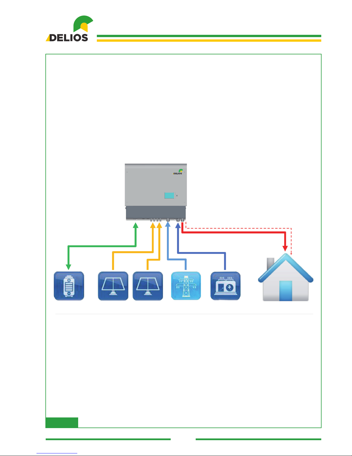
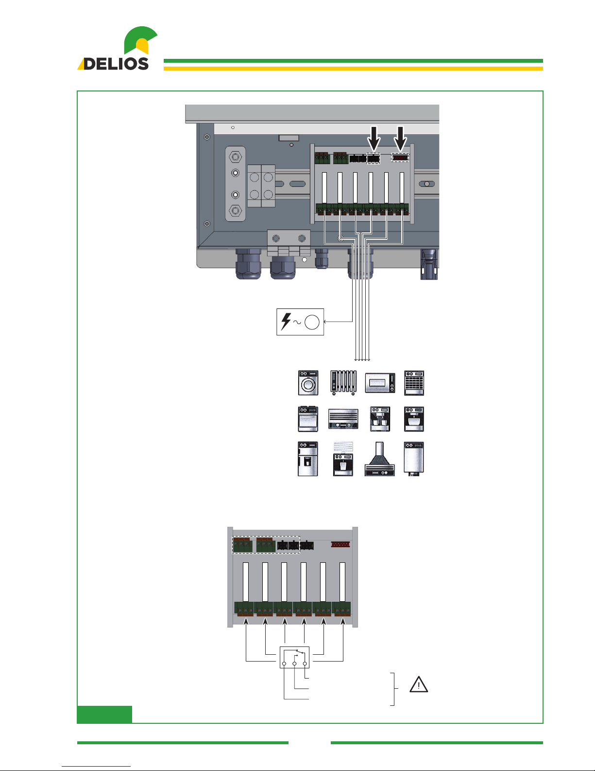
PROGRAMMABLE LOADS CONTROLS (*)
(*) - Optional
BATTERY PACK PV STRING 1 PV STRING 2 MAINS MOTOR GENERATOR (*)HOME LOADS
Fig. 00
4
Code 240.010.0001
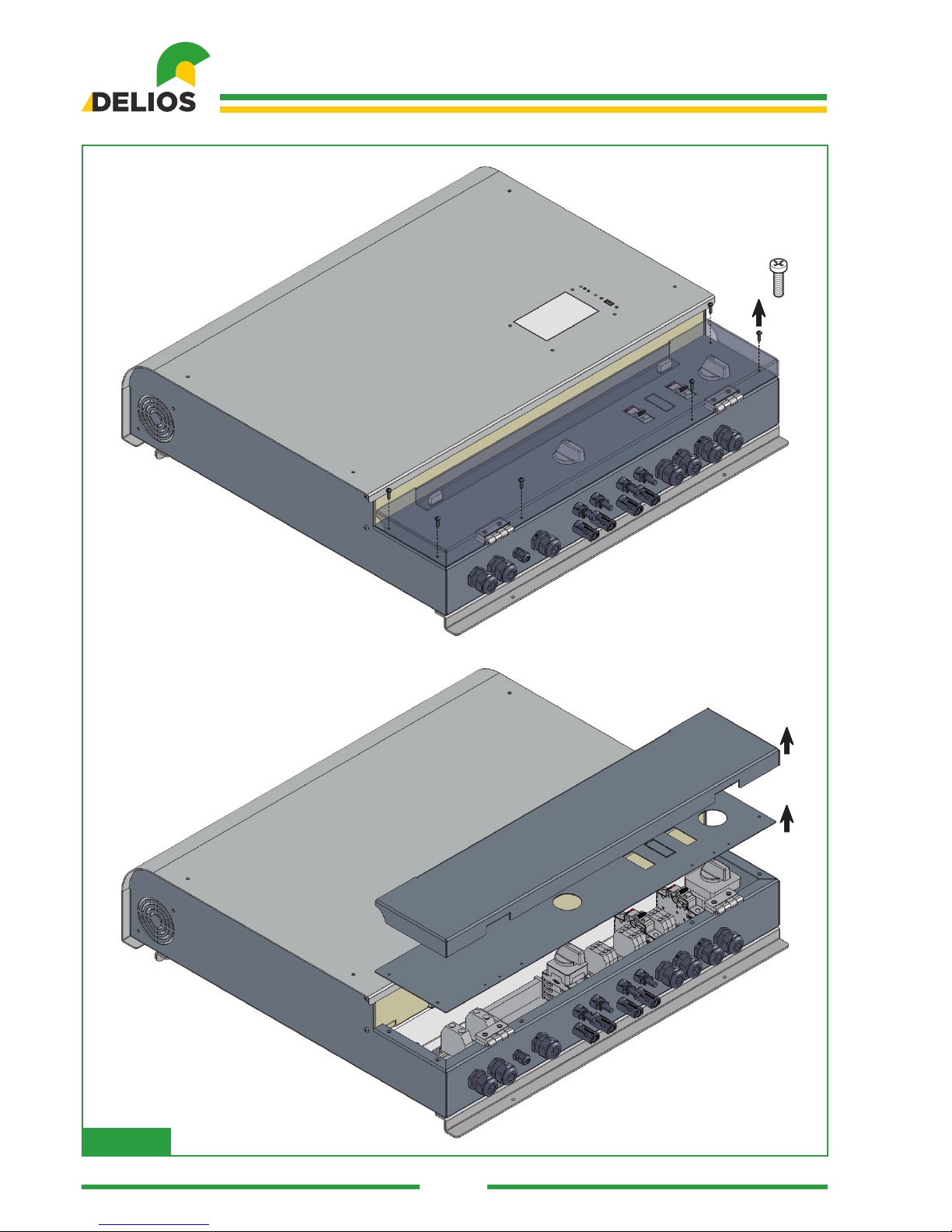
DLS 300 / 450 / 600
Fig. 01
DLS 300 / 450 / 600
5
Code 240.010.0001
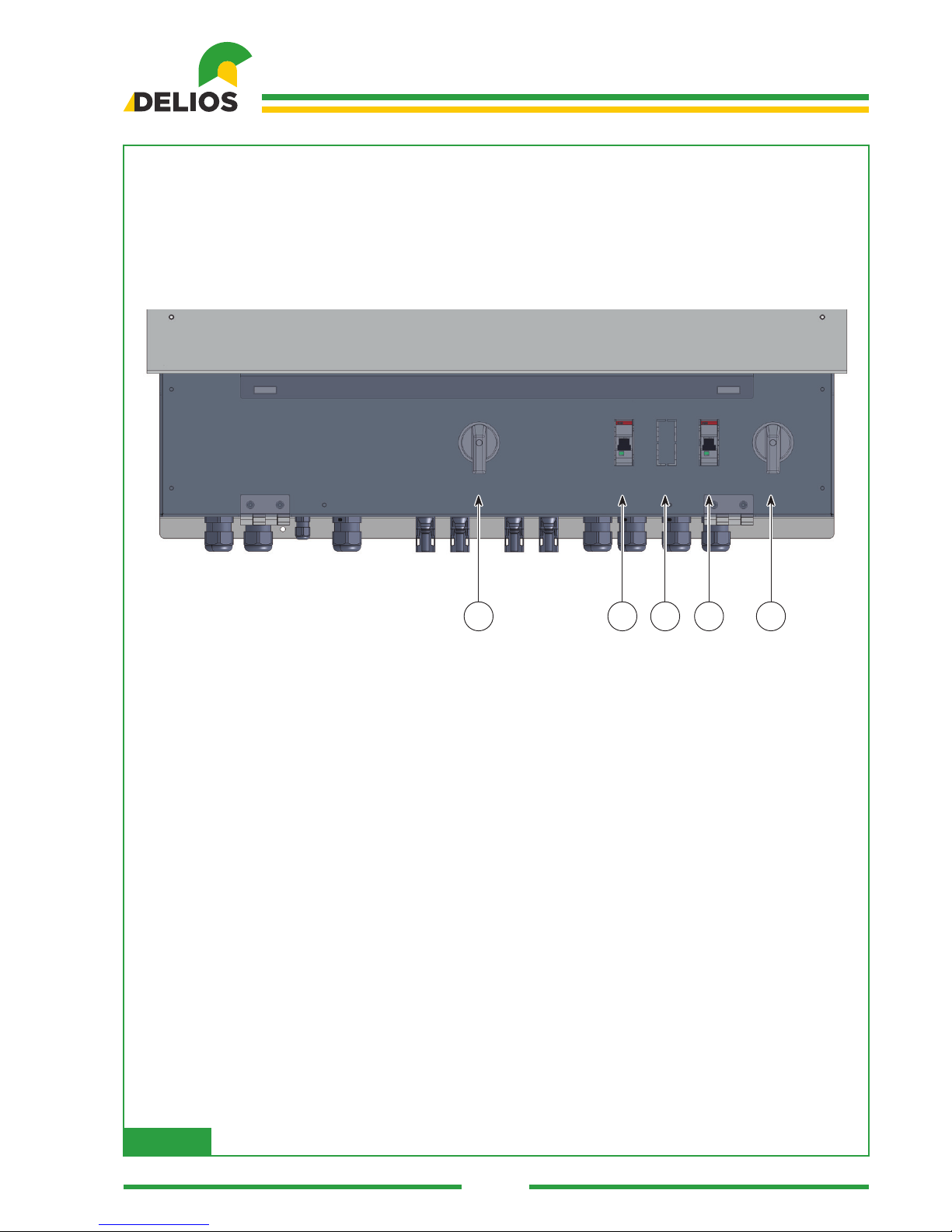
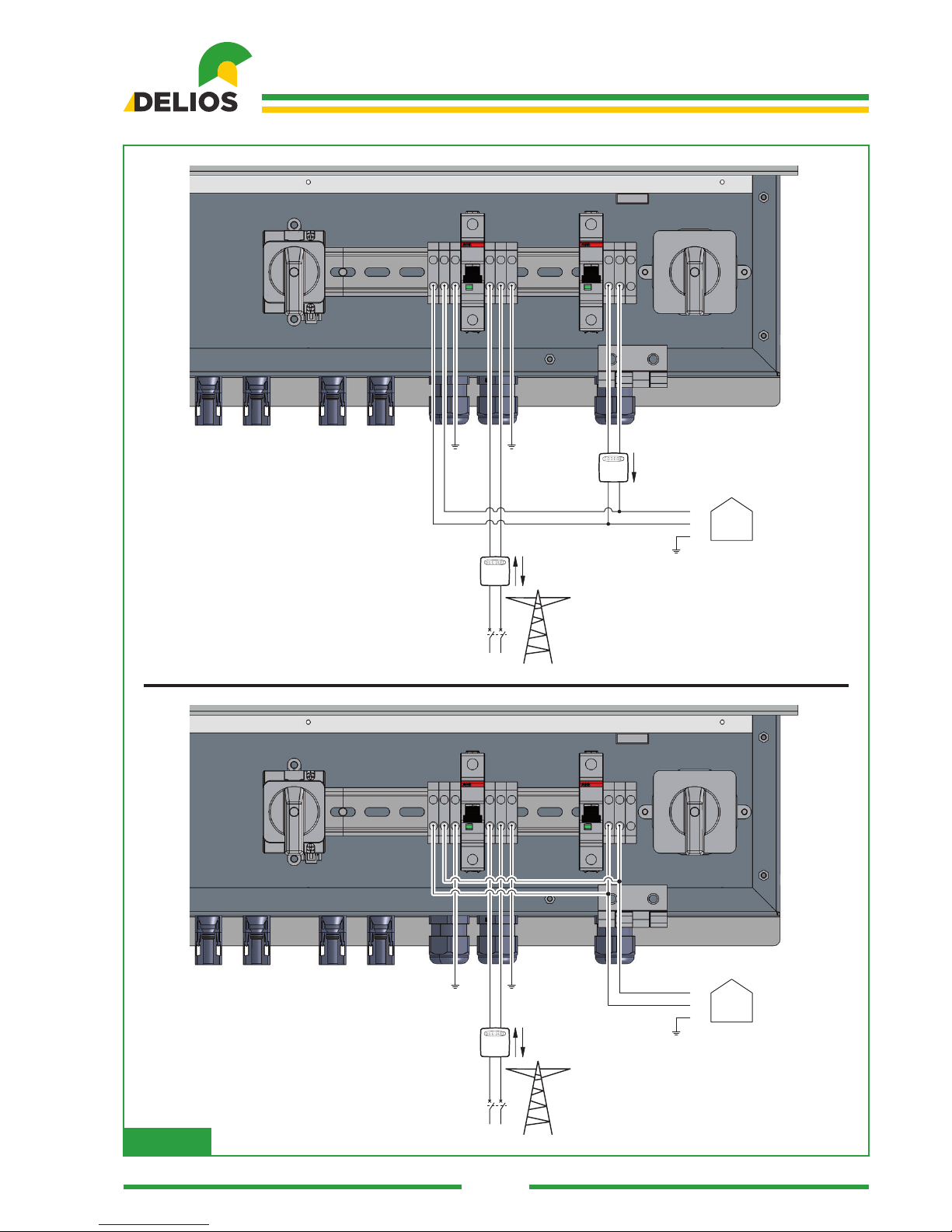
1 - DC SWITCH
2 - AC GRID CIRCUIT BREAKER
3 - GEN (OPTIONAL) CIRCUIT BREAKER
4 - AC OUT CIRCUIT BREAKER
5 - AC BYPASS SWITCH
0
I
I
0
DC
AC GRID AC BYPASSAC OUTGEN
1 2 3 4 5
Fig. 02

6
Code 240.010.0001
DLS 300 / 450 / 600
+
-
+
-
+ BATTERY -
AC GRIDMETER
AC OUTGEN
1 2
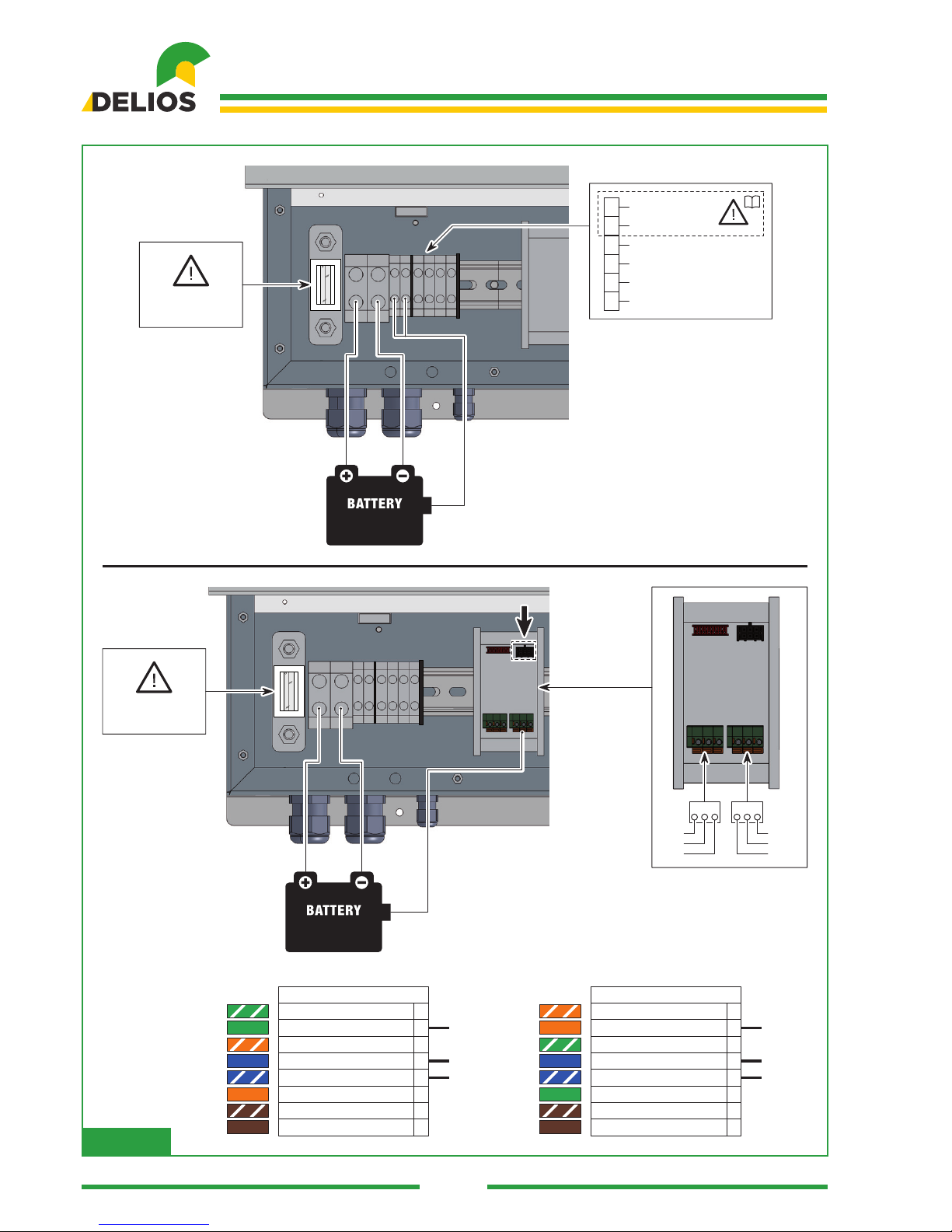
1 - BATTERY INPUT
1 2 3 6 7 8 94 5
2 - BATTERY TEMPERATURE SENSOR
3 - EXTERNAL WIRING (REFER TO “ACCESSORIES”)
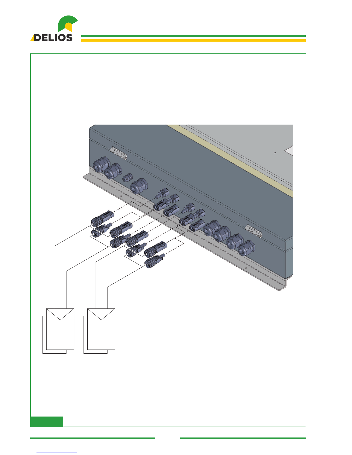
4 - PV1 STRING INPUT
5 - PV2 STRING INPUT
6 - PRODUCTION METER CONNECTION
7 - PUBLIC AC GRID INPUT
8 - MOTOR GENERATOR INPUT (OPTIONAL)
9 - HOME LOADS AC OUTPUT
Fig. 03

DLS 300 / 450 / 600
7
Code 240.010.0001
+
-
+
-
+ BATTERY -
AC GRIDMETER
AC OUTGEN
1 2
48V
TPV1
-
+
-
+
PV2
HOME LOADS CONTROL
GEN ON/OFF
G
In
017763
017763
i
Fig. 04
8
Code 240.010.0001
DLS 300 / 450 / 600
6 x
Fig. 05
DLS 300 / 450 / 600
9
Code 240.010.0001
AC OUT
NL
METER
PE
AC GRID
NL
PE
PE
NL
NL
METER
NL
PE
AC GRID
NL
PE
AC OUT
NL
PE
017763
N
N
L
L
NL
017763
PE
PE
NL
NL
NL
PE
017763
N
L
PE
Fig. 06
10
Code 240.010.0001
DLS 300 / 450 / 600
PV1 PV2
+
-
+
-
-
+
-
+
-
+
-
+
Fig. 07

DLS 300 / 450 / 600
11
Code 240.010.0001
PV
+
-
+
-
-
+
-
+
Fig. 08
12
Code 240.010.0001
DLS 300 / 450 / 600
HL0
+12 3456
FUSE 100A
-
FUSE MAX 100A
80 VDC
48V
T
1
2
NTC BATT +
NTC BATT -
GND
AL_EXT
3
4
T_D
S_E
5
6
i
PERICOLO
FUSE MAX 100A
80 V
+1
RS485 CAN
23456
FUSE 100A
-
DC
48V
RJ45
1Green/White Tracer
RJ45 Pin#
T568A
2Green
3
Orange/White Tracer
4
Blue
5
GND
CAN-H
CAN-L
Blue/White Tracer
6
Orange
7
Brown/White Tracer
8
Brown
AB 0
GND
CAN-L
CAN-H
A
B
GND
1
Green/White Tracer
RJ45 Pin#
T568B
2
Green
3
Orange/White Tracer
4
Blue
5
GND
CAN-H
CAN-L
Blue/White Tracer
6
Orange
7
Brown/White Tracer
8
Brown
Fig. 09

DLS 300 / 450 / 600
13
Code 240.010.0001
GEN
NL
PE
PE
N
L
PE
GEN ON/OFF
REMOTE CONTROL
(OPTIONAL)
G
Fig. 10
14
Code 240.010.0001
DLS 300 / 450 / 600
+12 3456
FUSE 100A
-
1
2
NTC BATT +
NTC BATT -
GND
AL_EXT
3
4
T_D
S_E
5
6
T_D
I
GND
S_E
i
PERICOLO
IT_CEI O-21
R >100k
GND
GND GND
Fig. 11
DLS 300 / 450 / 600
15
Code 240.010.0001
GENLD1 LD2LD3 LD4AUX
AUX GENERATOR
HOME APPLIANCES
G
COMMON
AC
SERVICE USE ONLY
GENLD1 LD2LD3 LD4 AUX
NO (NORMALLY OPEN)
NC (NORMALLY CLOSED) MAX 4A - 250V
Fig. 12
16
Code 240.010.0001
DLS 300 / 450 / 600
DELIOS s.r.l.
Corso Noblesville, 10
CITTADELLA (PD) - ITALY
DELIOS s.r.l.
Corso Noblesville, 10
CITTADELLA (PD) - ITALY
DELIOS s.r.l.
Corso Noblesville, 10
CITTADELLA (PD) - ITALY
DELIOS s.r.l.
Corso Noblesville, 10
CITTADELLA (PD) - ITALY
Fig. 13

DLS 300 / 450 / 600
17
Code 240.010.0001
TABLE OF CONTENTS
1 INTRODUCTION ...........................................................................................................................19
1.1 Fields of Application ..............................................................................................................19
1.2 Symbols Used in This Manual ..............................................................................................19
1.3 Warranty................................................................................................................................19
2 CAUTIONS ....................................................................................................................................20
2.1 Operating Environment and Restrictions ..............................................................................21
2.2 Dismantling, Removal and Disposal .....................................................................................22
2.3 Protecting Staff and Third Parties .........................................................................................23
2.4 Protection from Electric Shock..............................................................................................24
2.5 Electromagnetic Fields and Interferences.............................................................................24
2.6 IP Protection Rating ..............................................................................................................24
2.7 Signage and Data Decals .....................................................................................................24
2.8 Residual Risks ......................................................................................................................25
3 GENERAL DESCRIPTION............................................................................................................26
3.1 The DSL System...................................................................................................................26
3.2 Protective Devices ................................................................................................................26
3.2.1 Anti-islanding ........................................................................................................................26
3.2.2 Earth Leakages of PV Panels...............................................................................................26
3.2.3 Converter Earth Leakages ...................................................................................................26
3.2.4 Automatic Interlock System (IT)............................................................................................26
3.2.5 AC BYPASS Switch ..............................................................................................................27
3.2.6 AC GRID and GEN Inputs Magnetic Thermal Circuit Breaker (optional)..............................27
3.2.7 AC OUT Output Magnetic Thermal Circuit Breaker .............................................................27
3.2.8 DC Inputs String Switch........................................................................................................27
3.2.9 String Fuses..........................................................................................................................27
3.2.10 Battery Galvanic Isolation .....................................................................................................27
3.2.11 Battery Overcurrent Protective and Safety Fuse ..................................................................27
3.2.12 Battery Temperature Sensor .................................................................................................27
3.2.13 Automatic Battery Switch .....................................................................................................27
3.2.14 Additional Protective Devices ...............................................................................................27
3.3 Touch-screen Control Panel..................................................................................................28
4 INSTALLATION .............................................................................................................................28
4.1 Lifting, Transport and Unloading Instructions........................................................................28
4.2 Unpacking and Checks .........................................................................................................29
4.3 Checking the Box Contents ..................................................................................................29
4.4 Positioning the DLS ..............................................................................................................29
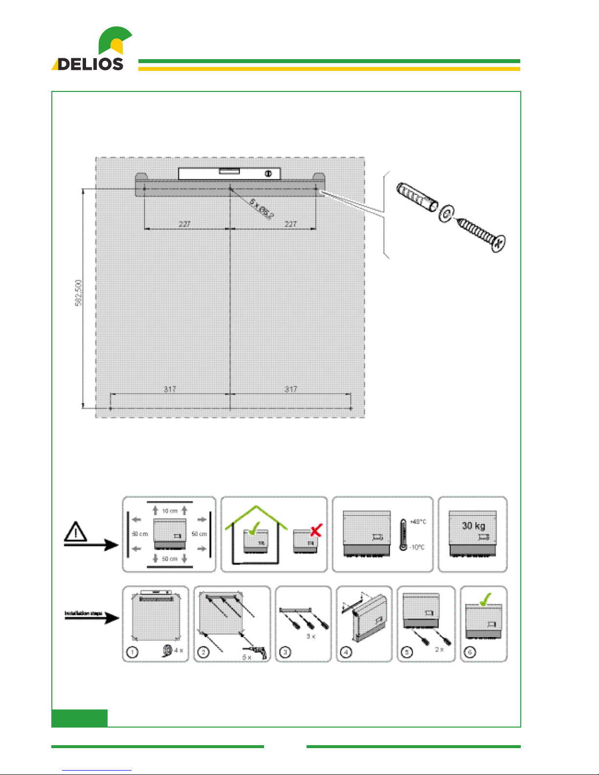
4.5 Mounting the DLS .................................................................................................................30
4.6 Connection............................................................................................................................30
4.6.1 Cautions................................................................................................................................30
4.6.2 Connection to the AC National Electricity Grid......................................................................31
4.6.3 Connecting the PV Panels....................................................................................................33
4.6.4 Connecting the 48V Lead-acid Battery .................................................................................34
4.6.5 Connecting the 48V Lithium Battery .....................................................................................35
4.6.6 Connecting an Auxiliary Power Generator (optional)............................................................36
4.7 Switching on the System.......................................................................................................37

18
Code 240.010.0001
DLS 300 / 450 / 600
5 CONTROL PANEL ........................................................................................................................38
5.1 General Information ..............................................................................................................38
5.2 “HOME” Screen ....................................................................................................................39
6 PROGRAMMING THE SYSTEM...................................................................................................41
6.1 “MENU’” Structure and System Navigation...........................................................................41
6.2 “MAIN” Menu.........................................................................................................................42
6.3 “LOGIN/LOGOUT” Menu ......................................................................................................43
6.4 “GRAPHICS” Menu...............................................................................................................44
6.5 “INFO” Menu .........................................................................................................................45
6.6 “SETTINGS” Menu................................................................................................................46
6.6.1 “MAIN” Menu.........................................................................................................................46
• “DATE AND TIME” Menu ......................................................................................................47
• “AUTO-TEST" Menu .............................................................................................................47
• “TOOLS’” Menu.....................................................................................................................47
• “LANGUAGE” Menu..............................................................................................................47
• “FIRMWARE UPGRADE” Menu ...........................................................................................47
• “BACKUP/RESTORE” Menu ................................................................................................48
6.6.2 “SYSTEM” Menu...................................................................................................................48
6.6.3 “GRID CODE” Menu .............................................................................................................48
6.6.4 “BATTERY” Menu .................................................................................................................48
• “LEAD” Menu ........................................................................................................................48
• “LITHIUM ” Menu ..................................................................................................................49
6.6.5 “HOME AUTOMATION” Menu ..............................................................................................49
6.7 “EXPORT” Menu...................................................................................................................50
6.7.1 “DATA” Menu.........................................................................................................................50
6.7.2 “EVENTS” Menu ...................................................................................................................50
7 ACCESSORIES.............................................................................................................................50
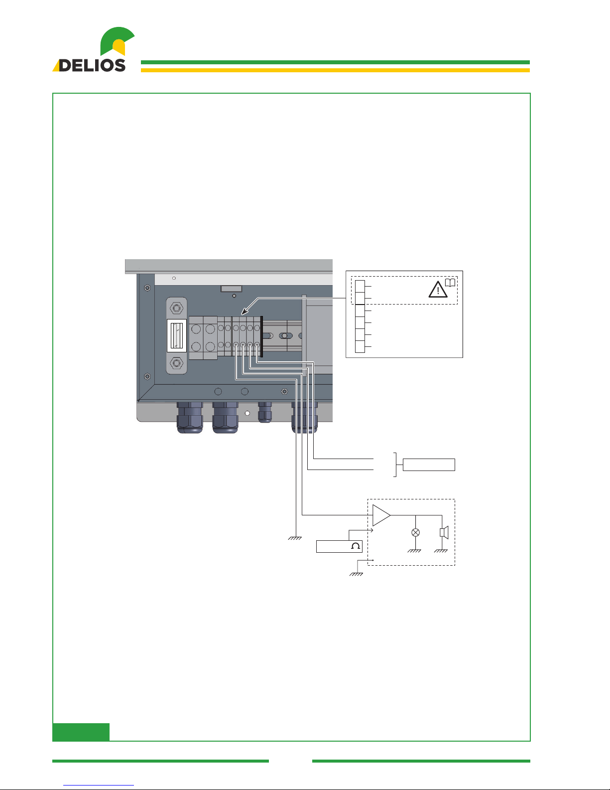
7.1 EXTERNAL ALARM Signal Connection................................................................................50
7.2
Connection between the REMOTE TRIPPING and the EXTERNAL SIGNAL (Italy - CEI 0-21)
...51
7.3 Home Automation PCB (optional) .........................................................................................51
7.3.1 Installation and Connections.................................................................................................51
7.3.2 Programming the Contact Controls.......................................................................................52
7.4 CAN/RS485 board (optional) ................................................................................................52
7.4.1 Installation and Connections.................................................................................................52
8 MAINTENANCE ............................................................................................................................52
8.1 General Information ..............................................................................................................52
8.2 Switching off the System ......................................................................................................53
8.3 Replacing the Battery Fuse...................................................................................................53
8.4 Disinstallation........................................................................................................................54
8.5 Disposal ................................................................................................................................54
9 TROBLESHOOTING .....................................................................................................................55
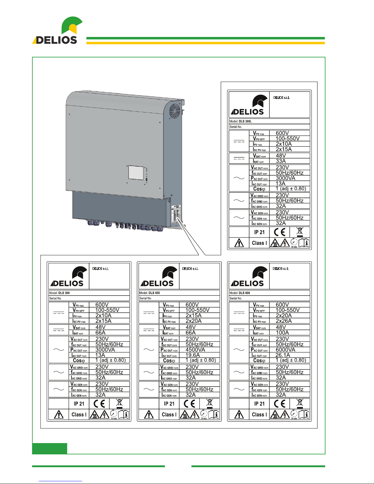
10 TECHNICAL DATA........................................................................................................................58
10.1 Nameplate.............................................................................................................................58
10.2 Technical Features................................................................................................................59

DLS 300 / 450 / 600
19
Code 240.010.0001
1 INTRODUCTION
1.1 Fields of Application
This installation manual is intended for qualied installers. The manual describes how to safely install, con-
nect and start up the following DLS systems:
• DLS 300
• DLS 450
• DLS 600
1.2 Symbols Used in This Manual
Imminent dangers causing serious injuries. Danger of death.
Hazardous behaviours that could cause serious injuries.
Hazardous behaviours that could cause death.
Behaviours that could cause minor injuries to people or minor damages to things.
The notes preceded by this symbol relate to technical issues and ease operations.
These instructions are intended for qualied engineers.
1.3 Warranty
Warranty Conditions Provided by DLS
Our quality control program ensures that each DLS product is manufactured exactly to specications and
is subjected to exhaustive tests before leaving our factory.
Five Year Warranty
The warranty provided by DELIOS s.r.l. lasts for 5 years from the DSL system purchase date. The warranty
conditions are based on the EU Directive 99/44/EC, except for any statutory rights.
Extended Warranty
For all DLS systems, customers can purchase a 5 year extension of the manufacturers' warranty, for a
maximum of 10 years. The warranty extension can only be purchased within 1 year from the DLS system
delivery date.
Warranty terms
Should DLS become faulty during the warranty period, one of the following services will be provided, at
the discretion of Customer Support Service (materials will be supplied for free, but labour costs will be
charged):
• Repair work carried out on DELIOS s.r.l. premises
• Repair work carried out on the installation site
• Replacing the defective unit with a new one (or one of the same value according its model and age)
20
Code 240.010.0001
DLS 300 / 450 / 600
Disclaimer
Warranty claims and responsibilities for direct or indirect damages are excluded if caused by:
• transport or storage damages
• incorrect installation and/or commissioning
• modications, changes or attempted repairs carried out by untrained and unauthorised staff
• incorrect use or inappropriate operation
• inadequate device ventilation
• failure to comply with applicable safety standards
• force majeure (such as lightening, overvoltages, storms, res)
• aesthetic imperfections not affecting the system operation
• damages caused by humidity and/or other environmental conditions
The installer/retailer who installed the DLS must return the faulty system to DELIOS s.r.l. Customer Support
Service, who reserves the right to replace the unit with another unit of equal or higher technical specica-
tions, at their own discretion.
Disclaimer
All rights related to the contents of this manual are owned by DELIOS s.r.l.. By using this manual, you ac-
cept the terms of this disclaimer clause. Every effort has been made by DELIOS s.r.l. to ensure the accu-
racy of this manual. However, DELIOS s.r.l. cannot accept responsibility for any errors or omissions in this
manual, nor for any damages caused by or associated with its use. No information published in this manual
can be copied or published in any way or by any means without prior written authorization by DELIOS s.r.l..
The information contained in this manual is subject to changes without notice, DELIOS s.r.l. does not have
any obligation to notify anything. After its publication, DELIOS s.r.l. does not have any obligation to update
or keep updating the information contained in this manual, and reserves the right to improve this manual
and/or the products described in this manual, at any time and without notice. We welcome your feedback
or advice if incorrect, misleading or incomplete information is found within the manual.
2 CAUTIONS
These instructions are provided for qualied engineers.
Before carrying out any operations, make sure to have read and understood this manual.
Do not make changes and do not carry out maintenance operations not described in this manual.
The manufacturer does not accept responsibility for injuries to people and damages to things occurred
because the information within this manual has not been read and followed.
The installation procedure must be carried out only by qualied staff.
The operations described herein must be carried out only by qualied engineers.
The customer is civilly liable for the qualications and mental and physical condition of members of staff
who operate this equipment. They must always use personal protective equipment required by the legisla-
tion enforced in the destination country and anything else provided by their employer.
The DLS system can also operate without being connected to the mains (off-grid). In these conditions,
default factory setting requires the inverter output to be automatically connected to ground by an internal
device before starting the off-grid operation. However, should the factory setting need to be changed for
specic requirements, the inverter output will be oating.
When exposed to the sun, PV panels can produce dangerous voltages. We recommend that the proce-
dures required to make the working area safe are carried out.
Other manuals for DLS 300
1
This manual suits for next models
2
Table of contents
Other Delios Inverter manuals


Popular Inverter manuals by other brands


Generac Power Systems
Generac Power Systems 04673-2 Installation and owner's manual

Generac Power Systems
Generac Power Systems QT06030KVAN owner's manual

Gallagher
Gallagher S220 Wiring instructions

Sollatek
Sollatek PowerBack PB3000S User instructions

Must Power
Must Power PV35 PRO-4K user manual

Commodore
Commodore HPD1500LB user manual

Asami
Asami AMV6-O224 Original instructions

Wagan
Wagan SOLAR e POWER CASE 800 user manual

Ginlong
Ginlong SOLIS S5-GC50K Installation and operation manual

Sinclair
Sinclair SDV5 Series Service manual

Bolanmu Energy
Bolanmu Energy AJ2100 quick guide

Mitsubishi Electric
Mitsubishi Electric FR-A520-2.2K instruction manual