Delixi NBZ User manual

NBZ Pour Sine Wave Inverter
User Manual
Standard: GB/T 19064, Q/DLX 342
□Please carefully read this User Manual before installing and
operating the product, and keep this manual properly for future
reference.

- 1 -
NBZ Pour Sine Wave Inverter
1. Introduction
1.1. This product is a pure sine wave inverter, and its output waveform is the same as that of the mains (power
grid); with advanced sine wave modulation technology used, it has strong shock resistance, and super-high output
capacity, suitable for various loads. This product can convert the DC 12V/24V/48V voltage provided by the
battery into AC 110V/220V voltage to supply the power to the load, and it is a second energy AC power supply.
1.2. Scope of Application
It is widely used in solar power generation systems, new energy storage systems, household appliances, and
industrial automation equipment systems, and can provide an ideal second energy AC power supply for household
appliances such as TVs, refrigerators, induction cookers, electric fans, microwave ovens, and air conditioners.
1.3. Product Features
●Pure sine wave output, soft start;
●Input and output completely isolated;
●Small size, and high efficiency;
●Microprocessor design;
●Electronic intelligent temperature controlled air cooling, good heat dissipation and energy saving;
●Built-in undervoltage, overload, short circuit, overvoltage, and over-temperature protections;
●With battery energy shortage and over-temperature alarm function;
1.2. Applied standard: Q/DLX 342 GB/T 190642
2. Important Safety Instructions
Please read this user manual carefully before installing and operating the inverter!
2.1 In order to reduce the risk, it is forbidden not expose the inverter in harsh environments such as rain, snow and
frost, foggy, greasy and dusty weathers; Also, do not install the inverter in a sealed place and do not cover and
block the vents, so as to avoid overheating damage to the inverter.

- 2 -
2.2. The inverter should be far away from the fire sources and electric shock, and failure to follow the wiring
requirements or the use of wires that do not comply with the standards may cause the abnormal operation or
damage to the inverter.
2.3 Because the inverter itself includes components that can easily generate arc, it is forbidden to install the
inverter in flammable or explosive environments and nearby the equipment without fire protection, including:
gasoline generators, inflammable fuel barrels or other component systems located near the fuel.
2.4. When installing the battery cable, if your skin or clothing touches the acidic substance of the battery, please
rinse it immediately with water, and go to the hospital for treatment in time if the circumstances are serious.
2.5 Do not put metal tools on the battery, because this is likely to cause the battery or other electronic components
explode due to fire sparks generated by short circuit.
2.6 t is strictly forbidden to put small metal items such as iron needles and iron pins into the product; far away
from water sources, and do not spray water on the product or in the product.
2.7 It is forbidden to allow the children operate this product, or touch the terminal posts or output ports of this
product with their fingers, so as to avoid the risk of electric shock.
2.8 Please turn off the AC and DC power before the maintenance, cleaning or connection of any circuit of the
inverter; do not dismantle the inverter, because the internal capacitor still stores electrical energy after all power
supplies are disconnected.
3. Protection Function
3.1. Input undervoltage protection: when the input battery voltage is too low, the red indicator light is on, and an
alarm sound is issued at the same time; the AC output will automatically turn off, indicating that the battery
voltage is lower than the protection setting value, and that the battery needs to be charged. The input voltage
protection setting values are as follows:
DC12V product input voltage is below 10±0.5V;
DC24V product input voltage is below 20±1V;
DC48V product input voltage is below 40±2V.
3.2. Input overvoltage protection: When the battery voltage is too high, FAULT red indicator light will be on, and
an alarm sound is issued at the same time; the AC output will automatically turn off, indicating that the battery
input voltage is higher than the protection setting value. The input voltage protection setting values are as follows:

- 3 -
DC12V product input voltage is higher than 15±0.5V;
DC24V product input voltage is higher than 30±1V;
DC48V product input voltage is higher than 60±2V.
3.3. Short circuit protection: In case of a short circuit at the output AC end, the inverter will automatically turn off
the output power supply.
3.4. Input protection with opposite polarity: When the battery cable is reversely connected, the fuse will be burnt
to protect the inverter.
3.5. Overheating protection: When the internal temperature of the inverter exceeds 65±5°C, the output AC end
will automatically turn off and an alarm indication will be issued, and it will be able to resume normal state after
about 15 minutes.
3.6. When charging, the terminal post and the input battery are connected with wires; when the product is in the
charging state, the master battery switch at the input end of the inverter should be turned on.
4. Normal Operation Conditions
The inverter can work reliably under the following environmental conditions:
4.1. Ambient temperature: -10°C~+40°C; the relative air humidity should be less than 85% (at an air temperature
of 20°C±5°C);
4.2. The altitude of the inverter installation site does not exceed 1000m;
4.3. The inverter operation site should be located inside the room free of vibration and shock, without conductive
or explosive dust, or gas that can cause corrosion to the metal or damage to the insulation.
4.4. The inverter must be installed in a dry place free from rain, spray, or splash water, and the safety vents on the
inverter must not be blocked to prevent the inverter from overheating.
4.5 Under working conditions where the upper limit of ambient air temperature exceeds +40°C or is lower than
-10°C, the user should contact the manufacturer for negotiation.
- 4 -
5. Working Principle
With the high-frequency DC/AC conversion technology used, the inverter can invert the low-voltage direct
current into high-frequency low-voltage alternating current that will be rectified into a high-voltage direct current
of about 300V after boost by the high-frequency transformer through the high-frequency rectification filter circuit,
and 220V power frequency alternating current can be obtained through the power frequency inverter circuit for
loads.
The inverter is made of high-frequency core materials featuring with small size and light weight, thereby greatly
improving the power density of the circuit and making that the no-load loss of the inverter power supply is small,
and the inverter efficiency is improved. The peak conversion efficiency is up to 90% and more.
6. Outline Drawing
There are an inverter, user manual, DC input wires, and spare fuses in the product package. See Fig. 1 (6.1, 6.2,
6.3)
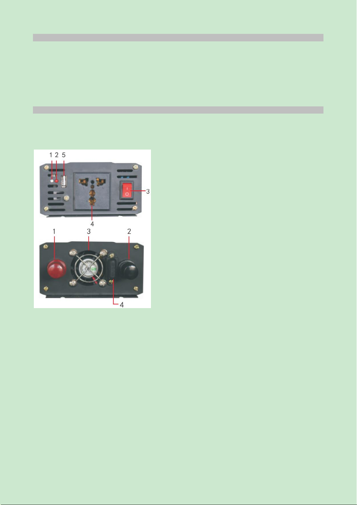
6.1 Pure sine wave inverter 300W~600W
Fig. 1:
Legends:
1. Run indicator
2. Red fault indicator
3. Power start switch
4. AC output socket
5. USB interface
Legends:
1. The red terminal block is DC input "+pole";
2. The black terminal block is DC input "-pole";
3. Heat dissipation fan;
4. Fuse device;

- 5 -
6.2 Pure sine wave inverter 1000W~2000W
Legends:
1. Run indicator
2. Red fault indicator
3. Power start switch
4. AC output socket
5. USB interface
Legends:
1. The red terminal block is DC input "+pole";
2. The black terminal block is DC input "-pole";
3. Heat dissipation fan;
4. Fuse device;
6.3 Pure sine wave inverter 3000W~5000W
Legends:
1. Run indicator
2. Red fault indicator
3. Power start switch
4/5. AC output socket
6. USB interface
Legends:
1. The red terminal block is DC input "+pole";
2. The black terminal block is DC input "-pole";
3/4. Heat dissipation fan;

- 6 -
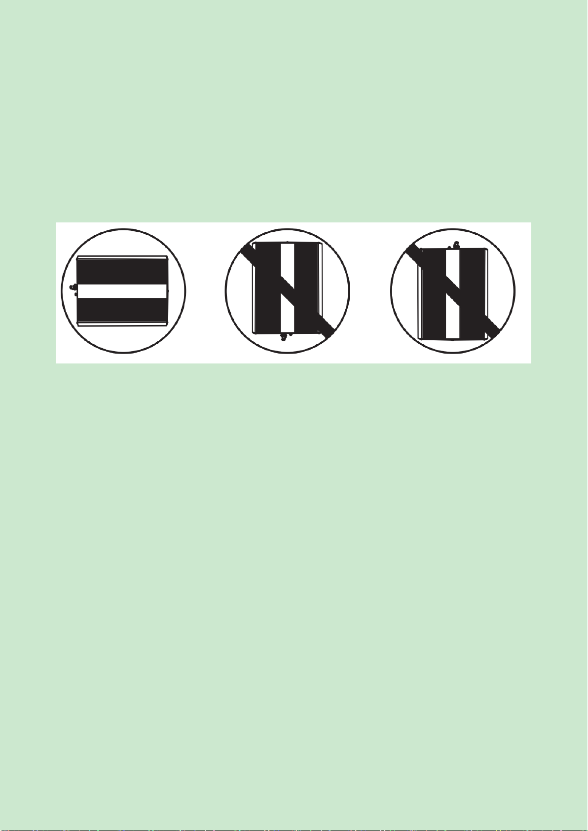
①-Inverter AC output socket: used for AC output load; the type can be selected from those shown in Figure 2
(factory default is the general type): Figure 2:
②- ON/OFF switch: used for turn on and turn off the inverter.
③- Fault lamp (red): it is lit and the AC output is turned off for inverter faults such as overvoltage, undervoltage,
overload, overtemperature, short circuit, and electric leakage.
④- Power indicator (green): indicates that the inverter is running.
⑤- USB port: output DC5V/500mA, USB output on the inverter is used by the external device of USB to provide
5V DC power; when the inverter is connected to the input voltage, the USB output is permanently switched on.
Warning: The USB port on the power supply is not used to transfer data!
Do not connect any data transmission cable to the USB port (such as: memory stick, MP3, and other
similar data storage external devices), so as not to damage the data storage device!
⑥"-" input DC negative terminal: connect the battery with the negative pole of the inverter with a black battery
wire, and the negative pole of inverter and the negative terminal of the battery are black.
⑦"+" input DC positive terminal: connect the battery with the positive terminal of the inverter with a red battery
wire, and the positive t pole of the inverter and the positive terminal of the battery are red.
Warning! Do not connect the polarity reversely, because the wrong connection will make that the fuse is burnt,
and may cause damage to the inverter.
⑧The cabinet grounding screw is grounded with a grounding wire, and the product must be well grounded before
use!
7. Operation Description
7.1 Battery selection: The battery capacity directly affects the inverter time of the inverter. Therefore, the inverter
power supply load and the battery capacity shall be determined, and then the battery is selected according to the
following steps:
7.1.1 The inverter input voltage is divided into DC12V, DC24V and DC48V voltage levels. According to the
product indicators, the valve-regulated or liquid-filled battery is used (Note: The configured battery voltage shall
not be higher than 1.6 times of that of the machine, otherwise this may easily cause damage to the inverter!).

- 7 -
7.1.2 Battery backup time depends on the battery capacity (Ah) and the electrical appliance (W) in your home; the
backup time calculation method:
Backup time =
Battery capacity (Ah) ×Battery voltage (V)÷Load power (W)
For example: Battery capacity is 150Ah, battery voltage is 12V, and load power is 600W
So: (150Ah×12V)÷600W=3 hours
Note: The time calculated in this way is a theoretical value; the actual time may be shorter than this value.
7.1.3 In order to prevent the inverter battery being discharged excessively, if the inverter is running only under the
light load, it is recommended to charge before the inverter low voltage off point is reached. For more information
on battery maintenance, please read the battery instructions or consult the battery manufacturer.
7.2 Inverter wiring: Turn the inverter switch to the OFF (turn off) position before connecting the inverter with the
battery (including the output electrical equipment);
7.2.1 Power obtained from the battery: the black wire is connected to the negative terminal of the black terminal,
and the red wire is connected to the positive terminal of the red terminal. Do not connect the positive and negative
poles inversely to avoid damage to the inverter.
7.2.2 The cabinet grounding screw must be well and reliably grounded!
7.3. After determining that the output voltage is stabilized, connect to the electrical equipment; the inverter switch
on the product cannot be used as an electrical switch; the start sequence is as follows: first turn on the inverter
switch, and then turn on the equipment switch; the stop sequence is as follows: first turn off the equipment switch,
and then turn off the inverter switch, otherwise this may cause damage to the product.
7.3.1 Plug the power cord of the AC appliance to be run into the AC power outlet; with the inverter switch turned
on, the red and green LED indicators are lit for 3~5 seconds, then the red LED indicator is off, and the green LED
indicator is on, indicating that the inverter is working normally to ensure that the output load does not exceed the
rated output power of the inverter.
- 8 -
7.3.2 When the inverter turns off, the overload LED may briefly "flicker", and a short sound "beep" will be issued
from the sound alarm, which is normal phenomenon. The same alarm may also be issued when the inverter is
connected to or disconnected from the battery.
7.3.3 The inverter can be connected only to the electrical appliances and equipment rather than connecting to the
mains line! The zero line of the inverter cannot be connected to the ground wire or the negative pole of the
battery! Warning: Do not connect to AC distribution wiring.
Warning: Keep the battery well ventilated in use, and flammable gases may be produced during charging or
discharging of the battery.
7.3.4 There are four mounting slots at the bottom of the inverter, and please select the appropriate position from
them. If installed on the wall, the product shall be installed horizontally as shown in Fig. 3: the inverter indicator,
switch, socket and terminal block shall be installed to ensure easy operation and visible observation. If installed
on a moving vehicle, the inverter shall be mounted on the floor or a safe flat surface (the area should be kept
clean, safe and well ventilated).
Fig. 3:
7.3.5 It is normal that the inverter starts repeatedly and the red indicator is on and off repeatedly for a short time;
if the equipment does not work normally after one minute, please turn off some loads or the inverter with high
power is used instead of it.
7.3.6 The product is protected by integrated electronic circuits, and can be automatically reset after protection.
There is a fuse inside the inverter; if the polarity is connected reversely, the fuse may be burnt, and shall be
replaced by the maintenance personnel; open the bottom and replace the fuse; there is a spare fuse in the inverter.

- 9 -
7.3.7 For safety in use, when installing the product battery, it is recommended to connect a DC fuse or circuit
breaker with rated current in series on the positive line of the battery as a short-circuit protection and input switch.
Determine and select a fuse that can withstand the current that may be generated by the battery, and select a fuse
or circuit breaker with the appropriate current rating (for example: DC150A recommended for 1000VA, and
DC200A recommended for 1500VA)
7.3.8 If found any abnormity or fault, do not open the product without permission to prevent electric shock,
because the internal capacitor still maintains electric energy when all power supplies are disconnected, and this
failed product shall be sent to the professional maintenance personnel for maintenance.
7.3.9 Precautions for scrap
When scrapping the inverter, please note that electrolytic capacitors of the main circuit and the electrolytic
capacitors on the printed panel will cause an explosion during burning, and plastic parts such as front panels will
generate toxic gas when burning. Therefore, please dispose them as industrial waste.
7.4. Battery wiring
7.4.1 Series wiring: Batteries connected in series will increase the total output voltage of the battery pack; each
battery is connected in series, and the DC voltage shall match with the input DC requirements of the inverter; even
if multiple batteries are connected, the capacity remains unchanged. Two 6VDC/200Ah batteries are connected to
form a 12VDC/200Ah battery power, as shown in Fig. 4:
Fig. 4:
Overcurrent protection
To 12 VDC inverter
12V battery pack (total capacity = 200Ahrs)
Fig. 4 Series battery wiring
- 10 -
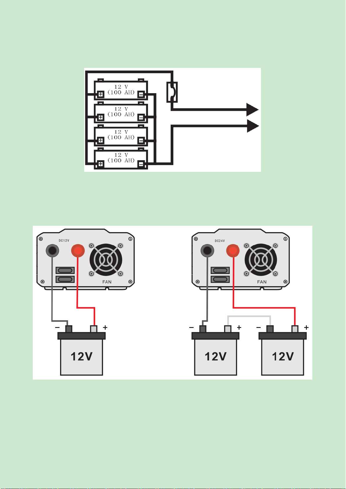
7.4.2 Parallel wiring: The parallel connection of batteries will increase the total running time of the AC load, and
the total capacity is the sum of the capacities of all batteries connected in parallel; even if there are multiple
batteries, the voltage remains unchanged. As shown in the figure (Fig. 5) below, four 12V DC/100Ah batteries
form a 12VDC/400AH battery pack.
Fig. 5:
Overcurrent protection
To DC12V inverter
12 V battery pack (total capacity = 400Ahrs)
Fig. 5 Parallel battery wiring
7.4.3 12V product wiring schematic diagram is shown in Fig. 6; 24V battery wiring schematic diagram is shown
in Fig. 7:
Fig. 6: Fig. 7:
12V inverter wiring method 24V inverter wiring method
- 11 -
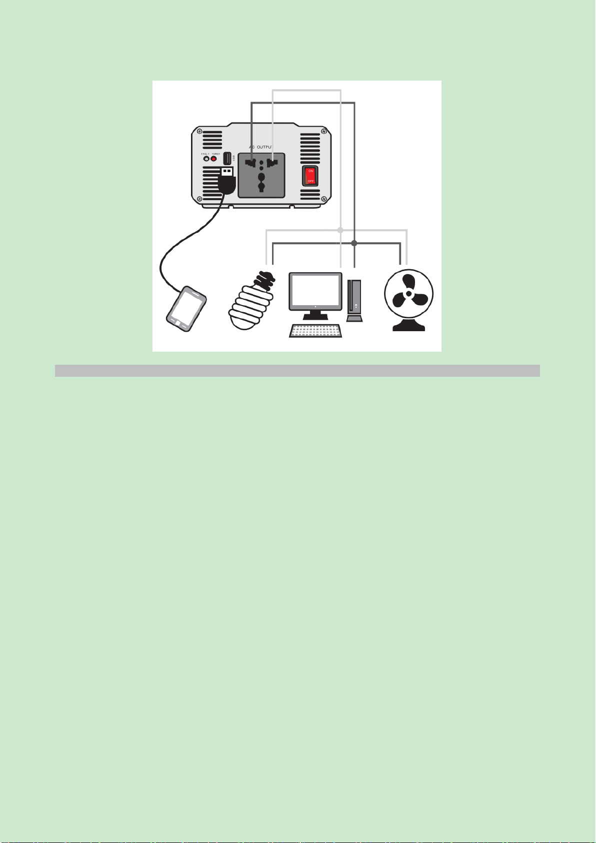
Output terminal connection method
8. Common Faults and Troubleshooting
8.1 When the inverter does not work, check the input wire for poor contact;
8.2 When the output voltage is too low, detect whether the load power exceeds the rated power;
8.3 When a low voltage alarm is issued, check whether the battery voltage is too low or the wiring is connected
properly;
8.4 Inverter overheating protection: put the inverter in a ventilated place for cooling;
8.5 The inverter fails to start: check whether the two poles are connected reversely, and whether the fuse is burnt.
8.6 The inverter does not operate; check whether the power switch is turned on, and whether the fuse and battery
cable are firmly connected.

- 12 -
The inverter shall be de-energized during installation, wiring connection, maintenance and troubleshooting,
and those operations shall be conducted by professional electricians or professional technicians to avoid
electric shock accidents or damage to the inverter!
Table 1: Common faults and troubleshooting
Fault
Cause
Solution
No AC output;
The red indicator is on;
The green LED is not lit.
1. DC input is below 10 V (battery
voltage is low);
2. The inverter is overheated and
turned off.
1. Charge or replace the battery.
2. Decrease the load and restart the
inverter after cooling down.
No AC output;
The red and green indicators are not
lit.
The inverter fuse is open-circuited
Open the inverter fuse seat or
housing and replace the fuse.
The inverter AC output is
intermittent;
Red indicator is lit and then off;
Green indicator is lit.
The output power of the inverter is
limited
Overloaded, and short circuit
protection
Reduce the load or eliminate the
short circuit, and restart the
machine
No AC output (lock);
Red and green indicators are lit.
Ground fault protection, or current
leakage from the load.
Remove the faulty load (electrical
appliance), and restart the machine
Battery backup time is shorter than
the expected time.
1. The capacity of selected battery is
too small, poor quality or damaged
2. The battery capacity is
insufficient or the voltage is low
1. Replace the battery with a new
one with large capacity.
2. Charge the battery, or use a
high-quality charger to charge the
battery.
No AC output;
The red LED is lit;
The green LED is not lit.
The input wire is too thin or too
long;
Too much current consumed in DC
wires
Use the battery cable of this
machine or the standard wire, and
shorten the length of the wire.
Low battery alarm sound is
abnormal
Poor input connection
Tighten all DC connection ends
Low battery alarm sound
1. Insufficient battery voltage:
2. The voltage level of the battery is
inconsistent with the inverter;
1. Charge or replace the battery.
2. Adjust the battery voltage level,
and reconnect the inverter.
TV interference
The device is too close to the
inverter
Increase the distance between the
inverter and the antenna.
Use a shielded antenna cable to
connect the antenna with the
amplifier.
9. Machine Files
One copy of Installation and Operation Instruction (including certificate);
1 set of fuses (adapted according to the product):
2 battery lines (12V input), and 4 lines for 2000VA and above.
10. Ordering Notice
10.1 Please specify the model, rated capacity, input voltage, output voltage, required quantity of the product when
ordering.
10.2 If you have special requirements, please sign a separate agreement.
- 13 -
Company Commitment
The company will provide the "three guarantees" service for any poor manufacturing quality causing that the
product cannot work normally under the normal storage, transport, maintenance, and operation conditions within
the 24 months from the date of production. For any damage due to one of the following situations, a paid repair
will be given even if within the warranty period:
(1) Improper operation, maintenance, or storage;
(2) Modified without permission or improper repair;
(3) Damage due to falling off or caused during installation after purchase;
(4) Force majeure such as earthquakes, fires, lightning strikes, abnormal voltages, and secondary disasters;
If you have any question, please contact the dealer or our company’s customer service department.
Customer service hotline: 400-826-8008
Certificate
DELIXI ELECTRIC LTD
Name: Pure Sine Wave Inverter
Model: NBZ Series
This product passes the inspection and is allowed to be
shipped.
Standard: Q/DLX 342
Inspector: Check 02
Production date: See label on inner box
DELIXI ELECTRIC LTD
Address: Delixi High-Tech Industrial Park, Liushi Town, Leqing City, Zhejiang P/C: 325604
Tel: (86-577) 6177 8888
Fax: (86-577) 6177 8000
Customer Service hotline: 400-826-8008
www.delixi-electric.com
The second edition of this manual was issued on August 2022.


