Segen Solar DDU-2000A User manual
Rev
1
User
Manual
Double Disconnect
20
0
0A
Segen Solar (Pty) Ltd Reserves the right to implement
changes to specifications depicted in this Installation manual
to conform to equipment or regulatory requirements
to conform to equipment or Regulatory requirements
Installation Manual
880KW-2000Amp AC N -Protection
- Double Disconnect Board
For Grid Tied olar Inverter ystems
Part Number: DDU-2000A
Rev
1
User
Manual
Double Disconnect
20
0
0A
Segen Solar (Pty) Ltd Reserves the right to implement
changes to specifications depicted in this Installation manual
to conform to equipment or regulatory requirements
to conform to equipment or Regulatory requirements
WARNING: All terminations should be checked for any potential loose connections that may
have occurred as a result of transport activities and vibration. Loose connection may cause
hot connections that could lead to damage and/ or fire
Introduction.
In accordance with local and international standards, the protection of equipment and
people are required to ensure the safe operation and maintenance of electrical products,
appliances or devices.
his AC protection is designed for both the protection and safe operation of the Solar
inverter it is designed for.
WARNING: Installation of this AC Protection board to be by qualified personnel only
WARNING: Electricity is dangerous- Please ensure the correct tools and personal protective
equipment is used when Installing, Wiring or Operating Electrical Equipment
WARNING: Although all precautionary measures are taken into account during
manufacturing it is the responsibility of the installer of this product to ensure that it
is installed in accordance with the relevant bylaws applicable to embedded
generation systems and low voltage electrical equipment

Rev
1
User
Manual
Double Disconnect
20
0
0A
Segen Solar (Pty) Ltd Reserves the right to implement
changes to specifications depicted in this Installation manual
to conform to equipment or regulatory requirements
to conform to equipment or Regulatory requirements
WARNING: his Electrical board has an IP65 rating, and is suitable for outdoor mounting.
Installation should where possible be done out of direct sunlight, direct water spray, and
rain. If this is not possible, it is recommended the board is to be fitted with a suitable rain
and sun canopy to protect from direct sunlight and rain or spray.
WARNING: In accordance with local bylaws and installation and wiring of premises, this
board should be installed in such a manner that maintenance and inspection can be carried
out without the use of special tools or equipment, such as ladders and scaffolding.
Description
his AC Board is designed for the connection and protection of a single or combiner PV
System input not exceeding a total of 2000A (880KW)
his double disconnect unit is controlled by the standard double disconnect control unit
which is a standard control unit for all the double disconnect units.
Once coupled with the double disconnect control unit the connection between the utility
grid and the PV Solar system is monitored by an independent grid monitoring relay and can
be configured according to the required Country Grid Code for its intended use. A secure
grid disconnection is required by series connection of two independently switched
contactors. he switching control is obtained from the Grid Monitoring Relay installed in the
control enclosure
his board is supplied pre-wired with the installer only required to connect the combined
output from the PV system, and the Utility side of the installation.
Ordering Code:
DDU-2000A

Rev
1
User
Manual
Double Disconnect
20
0
0A
Segen Solar (Pty) Ltd Reserves the right to implement
changes to specifications depicted in this Installation manual
to conform to equipment or regulatory requirements
to conform to equipment or Regulatory requirements
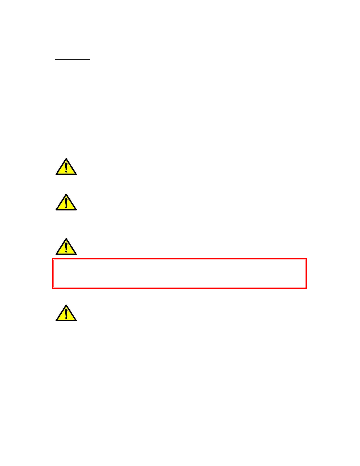
Mounting:
he board is designed to be floor mounted. Please ensure that the chosen surface is suitable
in order to support the weight of the board, for example Concrete plinth.
It is recommended that the board is mounted vertically.
Please ensure enough clearance area below the board to facilitate the incoming and
outgoing cables. Cables must be installed in such a way to maintain the cable manufacturers
recommended bending radius. See Fig 1.
Bending Radius according
o cable manufacturer
specifications
Height according to
cable connection
requirements
Fig 1.
DDU control unit
Rev
1
User
Manual
Double Disconnect
20
0
0A
Segen Solar (Pty) Ltd Reserves the right to implement
changes to specifications depicted in this Installation manual
to conform to equipment or regulatory requirements
to conform to equipment or Regulatory requirements
Connecting the PV System Combined Output cable to the Input o THE NSDD Board:
his AC Board is suitable for the connection of the following Inverter: up to 880KW
Max output Power: 8 x 110kW Inverter or 11 x 80kW Inverters or 22 x 40kW Inverters
etc
he Number of Inverters exceeding the quantity of one must first be combined in an AC
PV Combiner Board as this Board is designed to accept a single input from the PV System.
Recommended cable entry point is from the bottom of the enclosure. See Fig 2.
Utility Side
Connection
PV System
Connection
Fig 2.
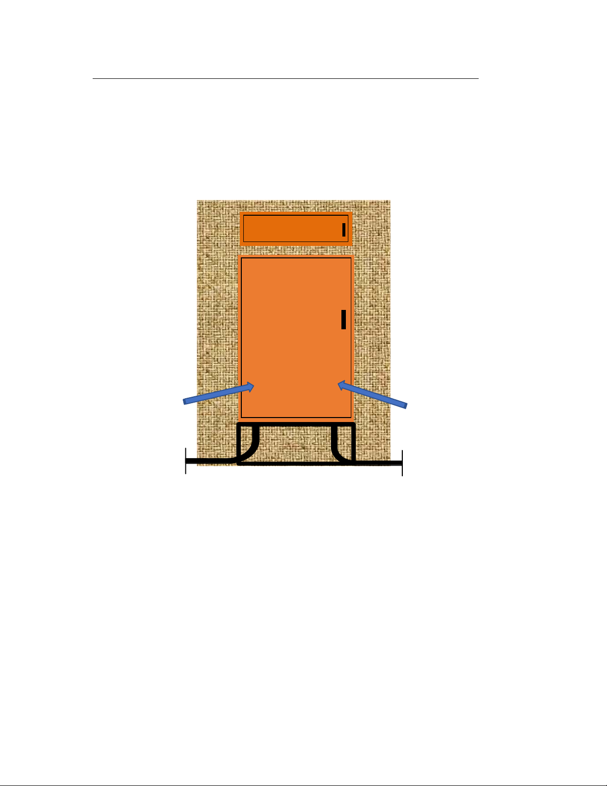
Note: Please use the appropriate cable gland for the cable type that is used for the
installation.
For SWA cable: Steel wire armoured gland with cone
For Flexible cable ie. H07-RNF- suitably selected IP 65 Compression gland
In all instances ensure the use of the matching shroud to protect the gland and assist with
ingress protection. See Fig 3,3a, and 4 below.
Rev
1
User
Manual
Double Disconnect
20
0
0A
Segen Solar (Pty) Ltd Reserves the right to implement
changes to specifications depicted in this Installation manual
to conform to equipment or regulatory requirements
to conform to equipment or Regulatory requirements
Fig 3 Fig 3a Fig 4
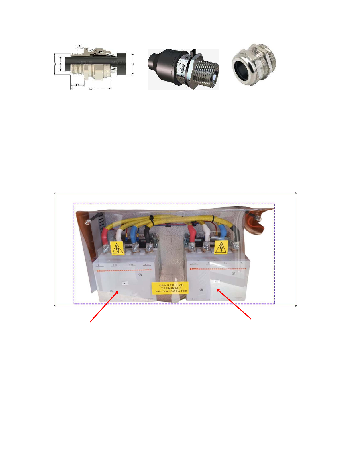
PV System AC Connection
Connect the PV System cable (L1, L2, L3, N) from the AC protection or combiner board to K2
contactor terminals as per Fig 5 below
K1 Air Circuit Breaker
– Utility Connection
Point
K2 Air Circuit Breaker- PV
Systems Connection Point
Fig 5
Recommended Cable Size: Main Cable – 3620mm² x 4C, Earth Conductor – 50mm² x 1C
Rev
1
User
Manual
Double Disconnect
20
0
0A
Segen Solar (Pty) Ltd Reserves the right to implement
changes to specifications depicted in this Installation manual
to conform to equipment or regulatory requirements
to conform to equipment or Regulatory requirements
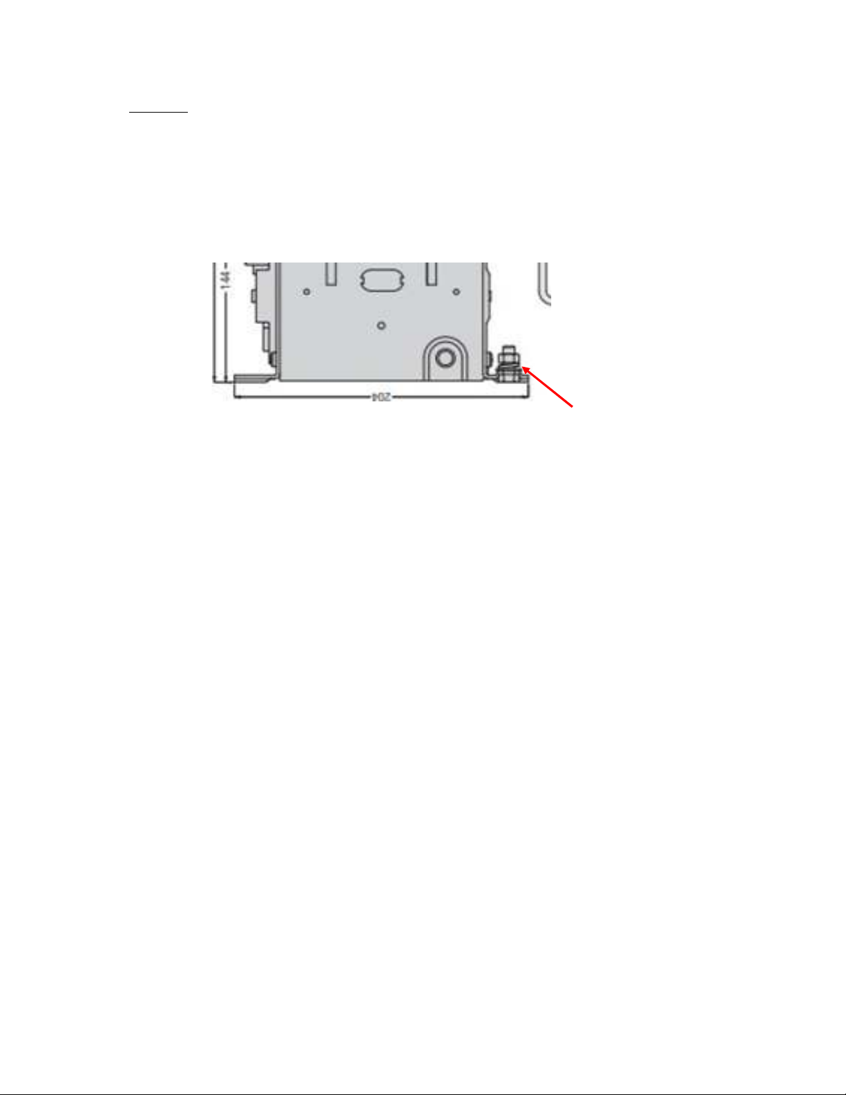
Earthing:
All Metallic parts of this assembly must be earthed in accordance with the Low Voltage
wiring standard requirements.
he Earth conductor for each individual cable must be connected to Earth Point Provided
See Fig 6 Below
M8- earth Stud
Fig 6
Conduct an insulation test prior to final connection of all connected cables
NB - Ensure all Cable are properly fastened to avoid loose connections prior to
powering system

Rev
1
User
Manual
Double Disconnect
20
0
0A
Segen Solar (Pty) Ltd Reserves the right to implement
changes to specifications depicted in this Installation manual
to conform to equipment or regulatory requirements
to conform to equipment or Regulatory requirements
Warranty:
his system carries a standard 12-month Warranty from date of purchase.
Warranty shall be void if not used within strict compliance with the installation manual, and
the user manual of the protection relay.
WARNING: Please ensure all connections including factory connections are checked, as
it is possible for them to loosen during transport and handling.
he ACDB is supplied with the appropriate marking and rating labels, please ensure any
additional warning or rating information is added to the system as may be required due to
site specific conditions and location.
SAFE Y FIRS - Equipment to be inspected and tested by suitably Qualified person
Table of contents


