Dell EMC VNXe3100 User manual

This document describes how to add a second storage processor (SP) to a VNXe3100 or
VNXe3150 disk processor enclosure (DPE).
Before you start
Before you begin the upgrade procedure
:
◆Make sure you have a current backup of your system data before you begin this (or any
other) upgrade procedure.
◆Make sure your VNXe system is running Maintenance Release 1 Service Pack 1
(version 2.1.1) or later. See the Unisphere online help for information about updating
your system software.
◆Make sure you have a new storage processor available to replace the cache protection
module, four 4 GB memory modules, and any I/O module required to match the
current SP. You also need appropriate network and SAS cabling to duplicate the
connections to SP A.
◆Refer to your EMC VNXe online help (Servicing your system > Adding or replacing
faulted hardware components > Add a new hardware component) for instructions on
how to handle hardware components. Take particular care to review the instructions
on avoiding electrostatic discharge (ESD).
IMPORTANT
Since the procedure to upgrade from a single SP to two SPs involves reboots and the
temporary quiescence of the sole processor, your system will not process or make
available any data until the procedure is finished. Plan you upgrade accordingly.
EMC® VNXe3100/VNXe3150
Adding a Second Storage Processor
P/N 300-012-179
REV 03

2 EMC VNXe3100/VNXe3150 — Adding a Second Storage Processor
Tasks to add an SP
Tasks to add an SP
◆Task 1: Preparing the DPE for service......................................................................... 2
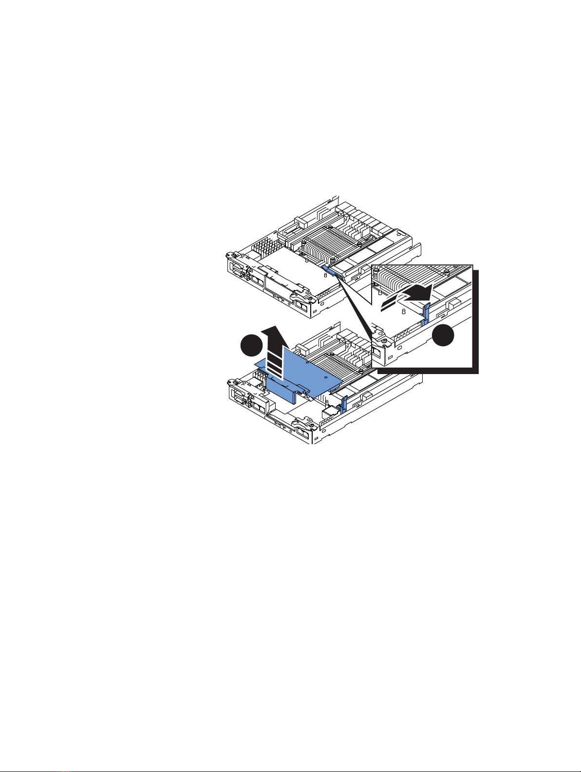
◆Task 2: Remove the cache protection module............................................................ 3
◆Task 3: Remove the storage processor A (SP A) assembly .......................................... 4
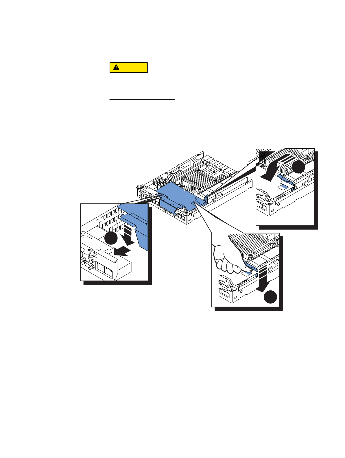
◆Task 4: Remove the SP top covers ............................................................................. 5
◆Task 5: Install an I/O module..................................................................................... 6
◆Task 6: Exchange the memory modules ..................................................................... 8
◆Task 7: Replace the SP top covers.............................................................................. 9
◆Task 8: Install the SP assemblies............................................................................... 9
◆Task 9: Connect SP B to the hosts and expanded storage ........................................ 10
◆Task 10: Power up the system ................................................................................. 10
◆Task 11: Validate the upgrade and reboot the system.............................................. 10
◆Task 12: Diable SSH................................................................................................ 11
◆Task 13: Verify the operation of the new SP assembly.............................................. 11
Task 1: Preparing the DPE for service
To prepare your system for the upgrade procedure:
1. Log into Unisphere™ and select Settings, then Service System.
2. Log in with your service password.
3. In the System Components column, select Storage System.
4. Under Service Actions, select Enable SSH, then Execute service action.
5. In the confirmation dialog box, click OK to enable SSH.
6. Download an SSH client, such as PuTTY, to a computer that has network access to the
system.
You may need to install the SSH client before you can launch it.
Run the Service Script
1. Launch the SSH client.
2. In the SSH client, use the management IP address to connect to the VNXe system.
For example, in PuTTY, type the management IP for the destination.
3. Log in as the Service user, then type the password for the Service account to log in to
the system.
4. Type the name of the upgrade script: svc_change_config.
5. Choose the upgrade (Convert to Dual SP, 8GB).
6. Type continue to confirm that you want to proceed with the upgrade.
If your system passes the ensuing health check the SP will boot to Service mode. The
reboot should take approximately five minutes.

Tasks to add an SP
EMC VNXe3100/VNXe3150 — Adding a Second Storage Processor 3
The SP fault LED will flash alternating amber and blue while the SP remains in Service
mode and is receiving active power.
Task 2: Remove the cache protection module
To replace a cache protection module with a storage processor, you must completely
power down your entire system, including any attached disk-array enclosures (DAEs).
DO NOT REMOVE a cache protection module while the “Unsafe to remove” LED is
on. The light indicates that you may interrupt a vital system or data-caching
process.
Wait until both “Unsafe to Remove” LEDs are off, then perform the following steps:
1. On the DPE and
each
DAE attached to the VNXe3100 or VNXe3150:
a. Release the cable retention bail and unplug the power cord from each power
cooling/module.
b. Mark the cords “A” or “B” for the power/cooling modules from which you removed
them.
2. Locate the two orange release levers on the cache protection module latches.
3. Squeeze the levers to release the latches and then pull the latches outward.
4. Pull out the latches until they are fully extended and the cache protection module is
released from its enclosure.
1
1
1
1 GBE
01
X4
6Gb SAS
6Gb SAS
23
1
0
e3e0 e1 e2
1 GbE
SP fault
CL4701

4 EMC VNXe3100/VNXe3150 — Adding a Second Storage Processor
Tasks to add an SP
5. Use the latches to slide the module about half-way out from its enclosure.
6. Use both hands to support the module and draw it fully out of the enclosure.
7. Place the cache protection module on a clean, flat, static-free work surface.
Task 3: Remove the storage processor A (SP A) assembly
To add a second SP assembly, you must remove the SP A assembly from the chassis, and
then exchange the 2 GB memory modules for 4 GB memory modules.
1. Disconnect the network cables from the back of the assembly.
Mark the cables with the port numbers from which you removed them.
The SP comes completely out of the chassis. In addition to holding the latches, be
prepared to support the SP to avoid dropping it.
2. Locate the left and right latches.
3. Pinch the orange tabs and pull the latches to the sides to eject the SP assembly from
the chassis.
4. Use the latches to slide the assembly about
half-way
out of the enclosure.
5. Use both hands to support the assembly and pull it fully out of the enclosure.
6. Place the assembly on a clean, flat anti-static work surface large enough to hold both
the assembly and its replacement.
CL4682

Tasks to add an SP
EMC VNXe3100/VNXe3150 — Adding a Second Storage Processor 5
Task 4: Remove the SP top covers
Before you start
Unpack the new SP assembly and place it on a clean, flat, static-free work surface, saving
the packaging material to return the cache protection module.
Procedure
Remove the SP cover from both SP A and the new second SP (SP B) assemblies:
1. Press the blue button on the SP cover.
2. Push the cover straight back 1/4 inch.
3. Lift the cover up.
2
3
1
CL4683

6 EMC VNXe3100/VNXe3150 — Adding a Second Storage Processor
Tasks to add an SP
Task 5: Install an I/O module
The storage processor in your upgrade kit does not include an I/O module. If the SP A
includes an optional I/O module, install a matching I/O module in the SP B assembly now.
If SP A does
not
include an I/O module, skip this task and continue with
Task 6: Exchange
the memory modules
on page 8
.
1. Lift the blue latch carefully until it ejects the I/O filler module from the connector.
2. Remove the filler module.
3. Unpack the I/O module and place it on a clean, flat, static free work area.
21
CL4688

Tasks to add an SP
EMC VNXe3100/VNXe3150 — Adding a Second Storage Processor 7
4. Angle the I/O module slightly so it fits into the canister and align it with the blue
alignment pins.
Do not attempt to seat the I/O module into the CPU connector while you are holding
the I/O module at an angle. Doing so will damage the connections. The I/O module
should be flat before you attempt to seat the connector.
5. With the module aligned and parallel to the CPU board, press the latch down to fully
seat the module in the connector.
6. Push down on the force point indicated on the I/O module to ensure that the module
is completely seated on the processor board.
5
6
4
CL4689

8 EMC VNXe3100/VNXe3150 — Adding a Second Storage Processor
Tasks to add an SP
Task 6: Exchange the memory modules
Remove each 2 GB memory module from both SPs and install the 4 GB replacements.
For each 2 GB memory module:
1. Rotate the memory module latches outward to release the module from the socket.
2. Touching only the outside edges, pull the module directly out of the socket, and place
it on an antistatic surface.
3. Remove the 4GB replacement module from its anti-static bag, and handling only the
outside edges of the module, align the module with the socket on the SP.
The socket and module are keyed to prevent incorrect alignment.
4. Firmly push the module directly into the socket.
The latches snap to the closed position when the module is fully inserted in its socket.
21
3
4
DIMM 0 DIMM 1

Tasks to add an SP
EMC VNXe3100/VNXe3150 — Adding a Second Storage Processor 9
Task 7: Replace the SP top covers
Replace the top cover on both SP assemblies:
1. Align the tabs on the SP cover with the notches in the canister.
2. Slide it forward 1/4 inch until the tab secures the cover.
Task 8: Install the SP assemblies
Install the new SP assembly in the left, “B” side of the enclosure and return the SP A
assembly the right, “A” side of the enclosure.
To install an SP assembly:
1. Pull out the latches on each side of the SP and make sure they stay in the open
position.
2. Align the SP with the chassis opening and push it straight into the chassis.
The latches begin to close when they contact the chassis edges.
3. Close the right and left latches to fully seat the SP in the chassis.
An audible click indicates that the latches are secure.
4. After installing the SP A assembly, reconnect all SP A network and SAS cables to their
original connectors.
2
1
CL4686
CL4687

10 EMC VNXe3100/VNXe3150 — Adding a Second Storage Processor
Tasks to add an SP
Task 9: Connect SP B to the hosts and expanded storage
Connect the new storage processor B to your management LAN, system hosts, and to any
DAEs in your current system. Most configurations provide high availability by mirroring the
storage processor “A” connections.
If SP A supports a DAE, connect a SAS cable from SP B SAS port 0 to the link control card
(LCC) B input port (labeled with two circles). Connect additional SAS cables as required
from the first DAE output port (labeled with two diamonds) to the input port of the next
DAE in the configuration.
Note: Cabling information, installation, configuration, and planning guides are available
on the Support Site at emc.com/vnxesupport.
Task 10: Power up the system
Power up the DPE and any connected DAEs in your system:
1. Plug each power cord in your system back into its power/cooling module.
2. Make sure you secure the power cords with the retention bails at each connector.
The bails prevent the power cords from pulling out of the connections.
Each enclosure in your system will power up immediately upon connection to an active AC
power source. The system boots into Service mode in approximately 15 minutes. The
storage processor fault LEDs will flash alternating amber and blue while the SP remains in
Service mode and is receiving active power.
Note: If the fault LED remains solid amber on either of the SPs, refer to “Troubleshooting
Notes” on page 12.
Task 11: Validate the upgrade and reboot the system
Once you have installed the SP assemblies in the chassis, and the SPs have booted into
Service mode (as indicated by alternating amber/blue fault LEDs), run the service shell
script to validate the upgrade and boot the system into Normal mode.
1. Launch the SSH client.
2. In the SSH client, use the management IP address to connect to the VNXe system.
For example, in PuTTY, type the management IP for the destination.
3. Type the password for the Service account to log in to the system.
4. Type the name of the upgrade script: svc_change_config --commit.
It may take 15 to 20 minutes for the system to complete its reboot and return to
Normal mode. The fault LEDs on the storage processors will cease flashing and go
completely off in Normal mode.

Tasks to add an SP
EMC VNXe3100/VNXe3150 — Adding a Second Storage Processor 11
Task 12: Diable SSH
Return your system to normal operating and security mode by disabling SSH:
1. If the Unisphere instance you used to enable SSH is still open, close it and then open
a new browser session.
2. Log in to Unisphere and select Settings, then Service System.
3. Log in with your service password.
4. In the System Components column, select Storage System.
5. Under Service Actions, select Disable SSH, then Execute service action.
6. In the confirmation dialog box, click OK to disable SSH.
Task 13: Verify the operation of the new SP assembly
Verify that the new SP B assembly and all its components are recognized by your system,
and operating correctly:
1. In Unisphere™, select System, then System Health.
2. Select the SP in the Component list or the graphical view:
• In the Component list, the new module should be marked with a status OK icon:
• In the graphical view, the module should be highlighted green.
The display highlights both storage processors in yellow until the boot process
completes.
3.
If you added an I/O module to either storage processor
:
• If you just installed an I/O module in SP A, the display will remind you to install the
second module in SP B.
If you just installed a second I/O module, follow the onscreen instructions to
Commit I/O modules.
• After you install and commit both I/O modules, the Component list should mark
them with a status OK icon:
• In the graphical view, the I/O module is highlighted green.
If the system health monitor continues to show the processor, memory, or I/O module
as faulted after you commit the I/O modules, contact your service provider.

12 EMC VNXe3100/VNXe3150 — Adding a Second Storage Processor
Troubleshooting Notes
This section describes troubleshooting steps to follow in the event that you are having
problems. Note that these troubleshooting steps apply
before
you validate the upgrade
and reboot the system to normal mode with the service script svc_change_config --commit
(see Task 8 “Validate the upgrade and reboot the system” on page 10); after that time,
please contact your service provider directly for assistance with your dual storage
processor system.
Problem: Running svc_change_config in normal mode, the following message is
displayed:
The upgrade cannot proceed. Please run the system health check
from the management application to determine the problem.
Solution: The service script detected a problem that prevents the upgrade. Running the
system health check from the management application is the best approach to diagnose
the problem.
Problem: After inserting an SP and restoring power, the SP does not reach service mode
(indicated by the fault LED alternating blue and amber); the fault LED remains solid amber.
Solution: The SP must be inserted firmly so that it will "seat" properly. Using the orange
release levers on the faulted SP, reseat the SP by sliding the SP out of the enclosure a few
inches and pushing it back in, being certain that the latches are fully closed to properly
seat the SP. Refer to “Task 8: Install the SP assemblies” on page 9.
Problem: When running svc_change_config --commit you see the following message:
You cannot commit the upgrade. Please verify that both SPs are
inserted, and both are running in service mode.
Solution: It takes somewhat longer for a newly inserted storage processor to complete
initialization and to reach service mode, than for the original storage processor, SP A. If
the fault LED on the back of SP B (the new storage processor) is not alternating amber and
blue after 20 minutes, then attempt to reinstall the storage processors (SP A and SP B):
1. Release the cable retention bail and unplug the power cord from each power supply.
2. Ensure all cables are labeled so they can be reconnected correctly.
3. Locate the two orange release levers on the SP B latches; squeeze the levers to release
the latches; and, then pull the latches outward.
4. Pull out the latches until they are fully extended and SP B is released from its
enclosure.
5. Use the latches to partially slide SP B from its enclosure.
When SP B is about half-way out of its enclosure, use both hands to support the
assembly and draw it fully out of the enclosure.
6. Follow steps 1-5 on SP A. Make sure to mark SP A with tape or some other means to
ensure that you return it to its original slot, and label all cables to ensure they are
reconnected correctly.
7. Remove and then reinstall the memory on SP A. Refer to “Task 6: Exchange the
memory modules” on page 8.
8. Remove and then reinstall the memory on SP B.

Troubleshooting Notes
EMC VNXe3100/VNXe3150 — Adding a Second Storage Processor 13
9. Reinstall SP A.
10. Reinstall SP B.
11. Reconnect all cables that were removed.
12. Reconnect the power cables to both SPs.
13. Continue with “Task 11: Validate the upgrade and reboot the system” on page 10.
Problem: You believe that you have a hardware problem, and want to abort the upgrade in
progress.
Solution: In the unlikely event that bad/damaged upgrade components were received and
your attempt to validate the upgrade failed, the upgrade may be aborted. You will need to
remove the parts that were added earlier in this procedure.
Note: Reviewyourdecisiontoaborttheupgradeprocedurewithyourserviceprovider.
1. From the service console in service mode, run command svc_change_config --abort.
It displays a message to restore the hardware to the previous configuration.
2. Wait for the prompt to return to the console window, which indicates that the service
script completed.
3. Release the cable retention bail and unplug the power cord from each power supply
(both SPs and any attached DAEs); and, label and remove all cables from both SPs.
4. Locate the two orange release levers on SP B latches.
5. Squeeze the levers to release the latches and then pull the latches outward.
6. Pull out the latches until they are fully extended and the SP B is released from its
enclosure.
7. Use the latches to partially slide SP B from its enclosure.
8. When SP B is about halfway out of its enclosure, use both hands to support SP B and
draw it fully out of the enclosure.
9. Place the SP B on a clean, flat, static-free work surface.
10. Return the cache protection module to slot B.
11. Locate the two orange release levers on the SP A latches.
12. Squeeze the levers to release the latches and then pull the latches outward.
13. Pull out the latches until they are fully extended and SP A is released from its
enclosure.
14. Use the latches to partially slide SPA from its enclosure.
15. When SP A is about halfway out of its enclosure, use both hands to support SP A and
draw it fully out of the enclosure.
Remove the new memory DIMMs placed in the DIMM slots on SP A and insert the
original memory DIMMs. Refer to “Task 6: Exchange the memory modules” on page 8.
16. Reconnect the power cables that were removed from any DAEs.
17. Reconnect all cables to SP A, including the power cable.

14 EMC VNXe3100/VNXe3150 — Adding a Second Storage Processor
Troubleshooting Notes
18. Connect the power cable to the cache protection module.
SP A should boot to normal mode.
19. Disable SSH, as described in “Task 12: Diable SSH” on page 11..
Copyright © 2012-2013 EMC Corporation. All rights reserved. Published in the USA.
Published January 2013
EMC believes the information in this publication is accurate as of its publication date. The information is subject to change without
notice.
The information in this publication is provided as is. EMC Corporation makes no representations or warranties of any
kind with respect to the information in this publication, and specifically disclaims implied warranties of
merchantability or fitness for a particular purpose. Use, copying, and distribution of any EMC software described in this
publication requires an applicable software license.
EMC2, EMC, and the EMC logo are registered trademarks or trademarks of EMC Corporation in the United States and other countries.
All other trademarks used herein are the property of their respective owners.
For the most up-to-date regulatory document for your product line, go to the technical documentation and advisories
section on EMC Online Support.
This manual suits for next models
1
Other Dell EMC Enclosure manuals