manuals.online logo
Brands
  1. Home
  2. •
  3. Brands
  4. •
  5. Dell
  6. •
  7. Server
  8. •
  9. Dell PowerEdge 2300 User manual

Dell PowerEdge 2300 User manual

ZZZGHOOFRP
®
'HOO3RZHU(GJH6\VWHPV
6(59,&(0$18$/
ZZZGHOOFRP
®
'HOO3RZHU(GJH6\VWHPV
6(59,&(0$18$/
____________________
Information in this document is subject to change without notice.
© 1998 Dell Computer Corporation. All rights reserved.
Reproduction in any manner whatsoever without the written permission of Dell Computer Corporation is strictly forbidden.
Trademarks used in this text:
Dell
,
the
DELL
logo, and
PowerEdge
are registered trademarks of Dell Computer Corporation;
MS-DOS
is a registered
trademark of Microsoft Corporation;
IBM
is a registered trademark of International Business Machines Corporation;
Intel
and
Pentium
are registered
trademarks and
MMX
is a trademark of Intel Corporation.
Other trademarks and trade names may be used in this document to refer to either the entities claiming the marks and names or their products. Dell
Computer Corporation disclaims any proprietary interest in trademarks and trade names other than its own.
April 1998 P/N 34365
v
&RQWHQWV
&KDSWHU 6\VWHP2YHUYLHZ  
System Features . . . . . . . . . . . . . . . . . . . . . . . . . . . . . . . . . . . . . . . . . . . . . 1-1
System Memory . . . . . . . . . . . . . . . . . . . . . . . . . . . . . . . . . . . . . . . . . . 1-4
Advanced Expansion Subsystem. . . . . . . . . . . . . . . . . . . . . . . . . . . . . . 1-5
Integrated Server Management. . . . . . . . . . . . . . . . . . . . . . . . . . . . . . . 1-5
Video Controller. . . . . . . . . . . . . . . . . . . . . . . . . . . . . . . . . . . . . . . . . . . 1-5
Integrated SCSI Controllers . . . . . . . . . . . . . . . . . . . . . . . . . . . . . . . . . . 1-5
SCSI Hard-Disk Drives . . . . . . . . . . . . . . . . . . . . . . . . . . . . . . . . . . . . . . 1-6
SCSI Configuration Guidelines. . . . . . . . . . . . . . . . . . . . . . . . . . . . . . . . 1-6
SCSI ID Numbers. . . . . . . . . . . . . . . . . . . . . . . . . . . . . . . . . . . . . . . 1-6
Device Termination . . . . . . . . . . . . . . . . . . . . . . . . . . . . . . . . . . . . . 1-7
System Power Supply . . . . . . . . . . . . . . . . . . . . . . . . . . . . . . . . . . . . . . 1-7
Pin Assignments for the DC Power Connectors . . . . . . . . . . . . . . . 1-7
DC Power Distribution . . . . . . . . . . . . . . . . . . . . . . . . . . . . . . . . . . . 1-9
System Board Layout . . . . . . . . . . . . . . . . . . . . . . . . . . . . . . . . . . . . . 1-11
SCSI Backplane Board Layouts . . . . . . . . . . . . . . . . . . . . . . . . . . . . . . 1-12
System Board Jumpers . . . . . . . . . . . . . . . . . . . . . . . . . . . . . . . . . . . . 1-13
Interrupt Assignments. . . . . . . . . . . . . . . . . . . . . . . . . . . . . . . . . . . . . 1-14
DMA Channel Assignments . . . . . . . . . . . . . . . . . . . . . . . . . . . . . . . . 1-15
Technical Specifications. . . . . . . . . . . . . . . . . . . . . . . . . . . . . . . . . . . . . . . 1-16
&KDSWHU %DVLF7URXEOHVKRRWLQJ 
Initial User Contact . . . . . . . . . . . . . . . . . . . . . . . . . . . . . . . . . . . . . . . . . . . 2-1
External Visual Inspection . . . . . . . . . . . . . . . . . . . . . . . . . . . . . . . . . . . . . . 2-2
Observing the Boot Routine . . . . . . . . . . . . . . . . . . . . . . . . . . . . . . . . . . . . 2-3
Internal Visual Inspection. . . . . . . . . . . . . . . . . . . . . . . . . . . . . . . . . . . . . . . 2-4
Eliminating Resource Conflicts . . . . . . . . . . . . . . . . . . . . . . . . . . . . . . . . . . 2-5
Running the Dell Diagnostics. . . . . . . . . . . . . . . . . . . . . . . . . . . . . . . . . . . . 2-6
Getting Help. . . . . . . . . . . . . . . . . . . . . . . . . . . . . . . . . . . . . . . . . . . . . . . . . 2-6
vi
&KDSWHU &RGHVDQG0HVVDJHV 
POST Beep Codes. . . . . . . . . . . . . . . . . . . . . . . . . . . . . . . . . . . . . . . . . . . . 3-1
System Messages. . . . . . . . . . . . . . . . . . . . . . . . . . . . . . . . . . . . . . . . . . . . 3-4
SCSI Hard-Disk Drive Indicator Codes. . . . . . . . . . . . . . . . . . . . . . . . . . . . 3-10
&KDSWHU 5HPRYLQJDQG5HSODFLQJ3DUWV  
Recommended Tools . . . . . . . . . . . . . . . . . . . . . . . . . . . . . . . . . . . . . . . . . 4-1
Precautionary Measures . . . . . . . . . . . . . . . . . . . . . . . . . . . . . . . . . . . . . . . 4-2
Front Bezel . . . . . . . . . . . . . . . . . . . . . . . . . . . . . . . . . . . . . . . . . . . . . . . . . 4-3
Computer Covers . . . . . . . . . . . . . . . . . . . . . . . . . . . . . . . . . . . . . . . . . . . . 4-4
Front-Bezel Inserts . . . . . . . . . . . . . . . . . . . . . . . . . . . . . . . . . . . . . . . . . . . 4-5
Control Panel Assembly . . . . . . . . . . . . . . . . . . . . . . . . . . . . . . . . . . . . . . . 4-6
Drives . . . . . . . . . . . . . . . . . . . . . . . . . . . . . . . . . . . . . . . . . . . . . . . . . . . . . 4-7
Externally Accessible Drives . . . . . . . . . . . . . . . . . . . . . . . . . . . . . . . . . 4-8
5.25-Inch Drives. . . . . . . . . . . . . . . . . . . . . . . . . . . . . . . . . . . . . . . . 4-8
3.5-Inch Diskette Drive . . . . . . . . . . . . . . . . . . . . . . . . . . . . . . . . . 4-10
Hard-Disk Drives . . . . . . . . . . . . . . . . . . . . . . . . . . . . . . . . . . . . . . . . . 4-11
SCSI Backplane Boards . . . . . . . . . . . . . . . . . . . . . . . . . . . . . . . . . . . . 4-12
Expansion Cards . . . . . . . . . . . . . . . . . . . . . . . . . . . . . . . . . . . . . . . . . . . . 4-13
System Power Supply. . . . . . . . . . . . . . . . . . . . . . . . . . . . . . . . . . . . . . . . 4-14
System Cooling Fans. . . . . . . . . . . . . . . . . . . . . . . . . . . . . . . . . . . . . . . . . 4-15
System Board Components . . . . . . . . . . . . . . . . . . . . . . . . . . . . . . . . . . . 4-17
DIMMs. . . . . . . . . . . . . . . . . . . . . . . . . . . . . . . . . . . . . . . . . . . . . . . . . 4-18
SEC Cartridge and Heat Sink Assembly . . . . . . . . . . . . . . . . . . . . . . . 4-19
Terminator Card. . . . . . . . . . . . . . . . . . . . . . . . . . . . . . . . . . . . . . . . . . 4-21
System Battery . . . . . . . . . . . . . . . . . . . . . . . . . . . . . . . . . . . . . . . . . . 4-22
System Board Assembly . . . . . . . . . . . . . . . . . . . . . . . . . . . . . . . . . . . . . . 4-23
System Board . . . . . . . . . . . . . . . . . . . . . . . . . . . . . . . . . . . . . . . . . . . 4-24
Guide Bracket Assembly . . . . . . . . . . . . . . . . . . . . . . . . . . . . . . . . . . . 4-25
$SSHQGL[$ 6\VWHP6HWXS3URJUDP  $
System Setup Screens . . . . . . . . . . . . . . . . . . . . . . . . . . . . . . . . . . . . . . . . A-2
,QGH[
)LJXUHV Figure 1-1. Computer Orientation . . . . . . . . . . . . . . . . . . . . . . . . . . . . . . . 1-2
Figure 1-2. Front-Panel Features . . . . . . . . . . . . . . . . . . . . . . . . . . . . . . . . 1-3
Figure 1-3. Back-Panel Features . . . . . . . . . . . . . . . . . . . . . . . . . . . . . . . . 1-3
Figure 1-4. Back/Right Side Internal View . . . . . . . . . . . . . . . . . . . . . . . . . 1-4
Figure 1-5. DC Power Connector P1 . . . . . . . . . . . . . . . . . . . . . . . . . . . . . 1-8
Figure 1-6. DC Power Connector P2 . . . . . . . . . . . . . . . . . . . . . . . . . . . . . 1-8

vii
Figure 1-7. DC Power Connectors P3, P4, P5, and P6 . . . . . . . . . . . . . . . 1-9
Figure 1-8. DC Power Cables. . . . . . . . . . . . . . . . . . . . . . . . . . . . . . . . . . . 1-9
Figure 1-9. DC Power Distribution. . . . . . . . . . . . . . . . . . . . . . . . . . . . . . 1-10
Figure 1-10. System Board Components. . . . . . . . . . . . . . . . . . . . . . . . . . 1-11
Figure 1-11. 1 x 6 Hot-Pluggable SCSI Backplane Board. . . . . . . . . . . . . . 1-12
Figure 1-12. 2 x 2 Non–Hot-Pluggable SCSI Backplane Board. . . . . . . . . . 1-12
Figure 1-13. 2 x 3 Non–Hot-Pluggable SCSI Backplane Board. . . . . . . . . . 1-12
Figure 1-14. System Board Jumpers. . . . . . . . . . . . . . . . . . . . . . . . . . . . . 1-13
Figure 3-1. Hard-Disk Drive Indicators. . . . . . . . . . . . . . . . . . . . . . . . . . . 3-10
Figure 4-1. Front-Bezel Removal . . . . . . . . . . . . . . . . . . . . . . . . . . . . . . . . 4-3
Figure 4-2. Computer Cover Removal . . . . . . . . . . . . . . . . . . . . . . . . . . . . 4-4
Figure 4-3. Plastic Insert Removal. . . . . . . . . . . . . . . . . . . . . . . . . . . . . . . 4-5
Figure 4-4. Control-Panel Assembly Removal . . . . . . . . . . . . . . . . . . . . . . 4-6
Figure 4-5. Drive Hardware . . . . . . . . . . . . . . . . . . . . . . . . . . . . . . . . . . . . 4-7
Figure 4-6. Externally Accessible 5.25-Inch Drive Removal. . . . . . . . . . . . 4-8
Figure 4-7. Drive-Mounting Rail Removal . . . . . . . . . . . . . . . . . . . . . . . . . 4-9
Figure 4-8. 3.5-Inch Diskette Drive Removal. . . . . . . . . . . . . . . . . . . . . . 4-10
Figure 4-9. Hard-Disk Drive Removal. . . . . . . . . . . . . . . . . . . . . . . . . . . . 4-11
Figure 4-10. Removing a SCSI Backplane Board and Hot-Pluggable
Hard-Disk Drive Indicator Panel. . . . . . . . . . . . . . . . . . . . . . . 4-12
Figure 4-11. Expansion Card Removal. . . . . . . . . . . . . . . . . . . . . . . . . . . . 4-13
Figure 4-12. Power Supply Removal . . . . . . . . . . . . . . . . . . . . . . . . . . . . . 4-14
Figure 4-13. System Cooling-Fan Removal . . . . . . . . . . . . . . . . . . . . . . . . 4-15
Figure 4-14. System Board Components. . . . . . . . . . . . . . . . . . . . . . . . . . 4-17
Figure 4-15. DIMM Removal . . . . . . . . . . . . . . . . . . . . . . . . . . . . . . . . . . . 4-18
Figure 4-16. DIMM Installation . . . . . . . . . . . . . . . . . . . . . . . . . . . . . . . . . 4-18
Figure 4-17. SEC Cartridge Release Latches. . . . . . . . . . . . . . . . . . . . . . . 4-19
Figure 4-18. Removing an SEC Cartridge and Heat Sink. . . . . . . . . . . . . . 4-20
Figure 4-19. Terminator Card Removal . . . . . . . . . . . . . . . . . . . . . . . . . . . 4-21
Figure 4-20. System Battery Removal. . . . . . . . . . . . . . . . . . . . . . . . . . . . 4-22
Figure 4-21. System-Board Assembly Removal . . . . . . . . . . . . . . . . . . . . 4-23
Figure 4-22. System Board Removal. . . . . . . . . . . . . . . . . . . . . . . . . . . . . 4-24
Figure 4-23. Guide-Bracket Assembly Removal . . . . . . . . . . . . . . . . . . . . 4-25
Figure A-1. System Setup Screens . . . . . . . . . . . . . . . . . . . . . . . . . . . . . . A-2
viii
7DEOHV Table 1-1. DC Voltage Ranges . . . . . . . . . . . . . . . . . . . . . . . . . . . . . . . . . 1-7
Table 1-2. Jumper Descriptions . . . . . . . . . . . . . . . . . . . . . . . . . . . . . . . 1-14
Table 1-3. Interrupt Assignments. . . . . . . . . . . . . . . . . . . . . . . . . . . . . . 1-14
Table 1-4. DREQ Line Assignments. . . . . . . . . . . . . . . . . . . . . . . . . . . . 1-15
Table 1-5. Technical Specifications . . . . . . . . . . . . . . . . . . . . . . . . . . . . 1-16
Table 3-1. POST Beep Codes. . . . . . . . . . . . . . . . . . . . . . . . . . . . . . . . . . 3-1
Table 3-2. System Messages. . . . . . . . . . . . . . . . . . . . . . . . . . . . . . . . . . 3-4
Table 3-3. SCSI Hard-Disk Drive Indicator Patterns . . . . . . . . . . . . . . . . 3-11
Table A-1. System Setup Categories . . . . . . . . . . . . . . . . . . . . . . . . . . . . A-3
ix
x
5HDG7KLV)LUVW
A prerequisite for using this manualto service Dell computersystems is a basic
knowledge of IBM®-compatible PCs and prior training in IBM-compatible PC
troubleshooting techniques. In addition to information provided in this manual
and the
User’s Guide
that came with the system, Dell provides the
Installation
and Troubleshooting Guide
for troubleshooting procedures and instructions on
using the Dell Diagnostics to test the computer system.
:DUQLQJV&DXWLRQVDQG1RWHV
Throughout this manual, there may be blocks of text printed in bold type or in
italic type. These blocks are warnings, cautions, and notes, and they are used
as follows:
:$51,1*$:$51,1*LQGLFDWHVWKHSRWHQWLDOIRUERGLO\KDUPDQG
SURYLGHVLQVWUXFWLRQVIRUKRZWRDYRLGWKHSUREOHP
&$87,21$&$87,21LQGLFDWHVHLWKHUSRWHQWLDOGDPDJHWRKDUG
ZDUHRUORVVRIGDWDDQGSURYLGHVLQVWUXFWLRQVIRUKRZWRDYRLGWKH
SUREOHP
NOTE: A NOTE provides helpful information about using the computer system.
System Overview 1-1
&+$37(5
6\VWHP2YHUYLHZ
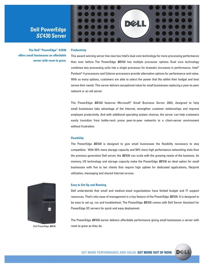
The Dell®PowerEdge®2300 systems are high-speed, upgradable, server
systems that use the Intel®Pentium®II family of microprocessors with
MMX™technology. PowerEdge 2300 systems incorporate the high-
performance PCI local bus as well as the ISA expansion bus.
The systems have been designed for better serviceability and increased reli-
ability. The PowerEdge 2300 systems are freestanding or can be rackmounted
for integrating your servers. The microprocessor(s) are mounted in modules on
the system board, which allows for greater heat dissipation. Contact Dell for
information about Dell-supported microprocessor upgrades.
PowerEdge 2300 systems can have one or two Pentium II microprocessors.
The microprocessor contains a built-in clock multiplier circuit, which increases
the internal operating frequency to a multiple of the system clock frequency.
The microprocessor has an internal operating frequency of 333 MHz and an
external operating frequency of 66 MHz, or an internal operating frequency of
350 or 400 MHz and an external operating frequency of 100 MHz.
6\VWHP)HDWXUHV
In addition to the standard features found in a traditional personal computer,
Dell PowerEdge 2300 systems include the following new and/or advanced
features:
512 KB of L2 cache memory internal to each Pentium II microprocessor
module
64 MB of 72-bit-wide, unbuffered, main memory, upgradable to 512 MB or
to 1 GB using 256-MB registered SDRAM DIMMs
Memory ECC feature built into the memory controller on the system board
Advanced combination ISA and PCI expansion subsystems
Four PCI and two combination ISA and PCI expansion-card slots
Integrated VGA-compatible AGP video subsystem with 2 MB of SGRAM
standard
BIOS in upgradable flash memory attached to the ISA bus
Integrated super I/O controller, attached to the ISA bus, that controls a
bidirectional parallel port, two serial ports, and the diskette drive interface
1-2 Dell PowerEdge 2300 Systems Service Manual
Integrated Ultra2/LVD SCSI controller that supports up to six hard-disk
drives via a backplane board and special drive carriers
Hot-pluggable hard-disk drive installation and removal when a PowerEdge
Expandable RAID Controller host adapter card and a hot-pluggable back-
plane board are installed.
Integrated Ultra/Narrow SCSI controller that supports up to three devices
in the external drive bays
Integrated server management circuitry that monitors operation of the sys-
tem cooling fan, as well as critical system voltages and temperatures
Front-panel drive failure and system fault indicators
Fora complete list of system features, see “Technical Specifications” found later in
this chapter.
For information about installing the PowerEdge 2300 systems in a rack, see
the
Dell PowerEdge 2300 Systems Rack Kit Installation Guide
.
When following the text in this manual, assume that the location or direction
relative to the computer is as shown in Figure 1-1. Figures 1-2 through 1-4 illus-
trate front-panel, back-panel, and interior features of the PowerEdge 2300
systems.
)LJXUH&RPSXWHU2ULHQWDWLRQ
back of computer
right side
left side
front of computer
System Overview 1-3
)LJXUH)URQW3DQHO)HDWXUHV
&$87,217RDYRLGSRVVLEOHGDWDRUILOHVWUXFWXUHFRUUXSWLRQVWKH
UHVHWEXWWRQVKRXOGEHXVHGRQO\ZKHQWKHV\VWHPFDQQRWEH
UHERRWHGE\SUHVVLQJ&WUO!$OW!'HO!%HIRUH\RXXVHWKHUHVHW
EXWWRQWRLQLWLDWHDKDUGZDUHUHVHWFORVHDQ\RSHQDSSOLFDWLRQVDQG
ILOHVLISRVVLEOH
)LJXUH%DFN3DQHO)HDWXUHV
power indicator
power button
reset button
hard-disk drive
access indicator
system alert indicator
hard-disk drive
failure indicator
keylock
CD-ROM drive
3.5-inch diskette drive
parallel port
connector
serial port 2
connector
mouse
connector
keyboard
connector
serial port 1
connector
video
connector
server-management
bus connectors (2)
SCSI
connector
ports (2)
expansion
slots (6)
AC power
receptacle
security
cable slot
1-4 Dell PowerEdge 2300 Systems Service Manual
)LJXUH%DFN5LJKW6LGH,QWHUQDO9LHZ
6\VWHP0HPRU\
System memory has a minimum of 64 MB of 72-bit-wide, unbuffered memory.
The system memory capacity can be expanded up to 1 GB by using combina-
tions of 64- and 128-MB unbuffered SDRAM DIMMs or 256-MB registered
SDRAM DIMMs.
NOTE: DIMMs must be rated to run at 100 MHz.
The system board has four 168-pin DIMM sockets. The DIMMs do not have to
be inserted in pairs. The socket population guidelines are as follows:
Populate the DIMM sockets in order from DIMM_A (upper) to DIMM_D
(lower).
The largest-capacity DIMM should be in socket DIMM_A, with smaller-
capacity DIMMs installed in decreasing sizes toward socket DIMM_D.
Unbuffered and registered DIMMs
cannot
be mixed. Remove any 64- or
128-MB unbuffered DIMMs before installing 256-MB registered DIMMs.
The 72-bit-wide, unbuffered DIMMs support the ECC feature, which detects
memory errors and corrects single-bit memory errors. The ECC feature pro-
vides more reliable memory and less downtime. The ECC feature is built into
the memory controller on the system board.
interface cable
DC power cable
system board
AC power receptacle
I/O panel
connectorsexternal drive
bays (4)
hard-disk drive
bays (4 or 6)
SCSI backplane board
expansion
slots (6)
System Overview 1-5
For more detailed information about DIMM installation guidelines and samples
of DIMM configurations, see “Adding Memory” in Chapter 8 of the
Dell
PowerEdge 2300 Systems Installation and Troubleshooting Guide
.
See “DIMMs” in Chapter 4 of this document for information on removing and
replacing DIMMs.
$GYDQFHG([SDQVLRQ6XEV\VWHP
The computer system offers advanced expansion subsystems that can support
a mixture of traditional ISA expansion cards, Plugand Play ISA expansion cards,
and PCI expansion cards. The Resource Configuration Utility (RCU) included with
the system provides a means of avoiding resource conflicts that might arise from
such an arrangement.
After all legacy cards have been configured with the RCU, the system automat-
ically assigns any required memory space, IRQ lines, and DMA channels to any
installed Plug and Play ISA expansion cards and PCI expansion cards the next
time the system is rebooted. Chapter 5, “Using the Resource Configuration
Utility,” in the
DellPowerEdge2300SystemsUser’s Guide
describesthe RCUand
provides instructions for using it to configure the system.
The six expansion-card slots include six PCI expansion-card connectors and
two ISA expansion-card connectors. Two of the PCI connectors share expan-
sion-card slots with the two ISA connectors. The expansion-card connectors
are located on the system board (see Figure 1-10).
,QWHJUDWHG6HUYHU0DQDJHPHQW
Integrated server-management circuitry monitors operation of the system fans
as well as critical system voltages and temperatures. The integrated server-
management circuitry works in conjunction with the HP OpenView Network
Node Manager Special Edition (NNM SE) and the Dell Hardware Instrumenta-
tion Package (HIP) software package.
9LGHR&RQWUROOHU
The video subsystem is built into the system board and consists of an AGP
VGA-compatible video subsystem with an ATI 3D RAGE PRO SVGA video
controller. The video subsystem contains 2 MB of SGRAM video memory,
which is not upgradable. Maximum noninterlaced resolutions are 640 x 480
(16.7 million colors), 800 x 600 (16.7 million colors), and 1024 x 768
(256 colors).
,QWHJUDWHG6&6,&RQWUROOHUV
An integrated Adaptec AIC-7890 Ultra2/LVD SCSI host adapter supports up to
six 1-inch internal SCSI hard-disk drives through a 68-pin connector on the sys-
tem board for a SCSI backplane board. The SCSI backplane board automatically
configures SCSI ID numbers and SCSI termination on individual hard-disk
1-6 Dell PowerEdge 2300 Systems Service Manual
drives, greatly simplifying drive installation. The integrated SCSI controller
resides on the PCI local bus for optimum performance.
An integrated Adaptec AIC-7860 Ultra/Narrow SCSI host adapter attached to
the PCI bus supports up to three SCSI devices in the external drive bays
through a 50-pin connector on the system board.
6&6,+DUG'LVN'ULYHV
Dell PowerEdge 2300 systems include a SCSI backplane board, which greatly
simplifies cabling and configuration for SCSI hard-disk drives. SCSI ID and ter-
mination for SCSI hard-disk drives are both configured by the SCSI backplane
board, rather than on individual drives. SCSI hard-disk drives are supplied by
Dell in special drive carriers that fit in the internal drive bays.
Three SCSI backplane board options (see Figures 1-11 through 1-13) include a
non–hot-pluggable 2 x 2 backplane, non–hot-pluggable 2 x 3 backplane, and
hot-pluggable 1 x 6 backplane boards. The hot-pluggable 1 x 6 backplane board
supports hot-pluggable SCSI hard-disk drive installation and removal.
NOTE: For maximum performance, install Ultra2/LVD drives exclusively.
Although you can install a mixture of Ultra2/LVD and Ultra hard-disk drives,
they will operate at the slower Ultra transfer rate.
6&6,&RQILJXUDWLRQ*XLGHOLQHV
SCSI hard-disk drives must be configured as follows:
Disable termination on the drive. The SCSI backplane board provides termi-
nation for the SCSI bus.
Set the SCSI ID on all drives to 0. All SCSI ID numbers for the drives are set
by the SCSI backplane board.
Configure the drive so that the drive motor waits for a start unit command
from the SCSI host adapter before spinning.
SCSI devices in the external drive bays are controlled by the Ultra/Narrow SCSI
controller on the system board. Although SCSI devices are installed essentially
the same way as other devices, their configuration requirements are different.
To configure SCSI devices installed in the external bays, follow the guidelines
in the following subsections.
6&6,,'1XPEHUV
Each device attached to the Ultra/Narrow SCSI host adapter must have a
unique SCSI ID number from 0 to 7.
When SCSI devices are shipped from Dell, the default SCSI ID numbers are
assigned as follows:
The on-board Ultra/Narrow SCSI host adapter is configured through the
BIOS as SCSI ID 7.
System Overview 1-7
A SCSI tape drive is configured as SCSI ID 6 (the default ID number for a
tape drive).
A SCSI CD-ROM drive is usually configured as SCSI ID 5.
NOTE: There is no requirementthatSCSIIDnumbers be assigned sequentially or
that devices be attached to the cable in order by ID number.
'HYLFH7HUPLQDWLRQ
All Dell PowerEdge 2300 systems have an active terminator installed at the
end of the SCSI cable.
All
of the devices attached to the SCSI cable should
have their termination disabled.
6\VWHP3RZHU6XSSO\
The 300-W system power supply can operate from an AC power source of
115 VAC at 60 Hz or 230 VAC at 50 Hz. The system power supply provides the
DC operating voltages and currents listed in Table 1-1.
NOTE: The power supply produces DC voltages only under its loaded condi-
tion. Therefore, when you measure these voltages, the DC power connectors
must be connected to their corresponding power input connectors on the sys-
tem board or drives.
.
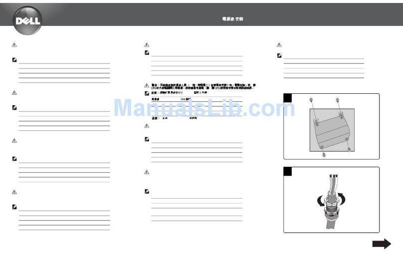
3LQ$VVLJQPHQWVIRUWKH'&3RZHU&RQQHFWRUV
The power-supply output voltages can be measured at the back (wire side) of
the connectors without disconnecting them. Figures 1-5, 1-6, and 1-7 show the
wire side of the connectors.
7DEOH'&9ROWDJH5DQJHV
9ROWDJH 5DQJH 0D[LPXP2XWSXW&XUUHQW
1
+3.3 VDC +3.15 to +3.45 VDC 18.0 A
+5 VDC +4.75 to +5.25 VDC 35.0 A
+12 VDC +11.40 to +12.60 VDC 14.0 A
–12 VDC –10.80 to –13.20 VDC 0.3 A
–5 VDC –4.50 to –5.50 VDC 0.3 A
+5 VFP
2
+4.75 to +5.25 VDC 1.2 A
1
Maximum continuous DC output power should not exceed 300 W. Maximum combined
load on +5 VDC and +3.3 VDC cannot exceed 200 W.
2
VFP (volts flea power) — sometimes called “standby power.”
1-8 Dell PowerEdge 2300 Systems Service Manual
1
Pin 13 — PSON# should measure between +4 and +5 VDC except when the power button
on the front panel is pressed, taking PSON# to its active-low state.
2
Pin 21 — Thermal fan-speed control (TFSC) is a power-supply input signal used to control
power-supply fan speed in special applications.
3
Pin 5 — PWRGOOD should measure +3.3 VDC when the power supply is operating to indi-
cate that all power-supply output voltages are within the ranges specified in Table 1-1.
)LJXUH'&3RZHU&RQQHFWRU3
)LJXUH'&3RZHU&RQQHFWRU3
13 14 15 16 17
P1
common (black)
+5 VDC (red)
TFSC2(brown)
+5 VDC (red)
PSON#1(gray)
common (black)
common (black)
common (black)
–5 VDC (white)
+3.3 VDC (blue/white)
18
+5 VDC (red)
19 20 21 22 23 24
+5 VDC (red)
12345
+12 VDC (yellow)
+3.3 VDC (blue/white)
common (black)
common (black)
+5 VFP (purple)
PWRGOOD3 (orange)
common (black)
+5 VDC (red)
common (black)
–12 VDC (blue)
6
+5 VDC (red) 789101112+3.3 VDC (blue/white)
1common (black)
P2
+12 V (yellow)
N/C
N/C
2345678
+3.3 VDC (blue/white)
common (black)
+12 V (yellow)
N/C
9
N/C
+5 V (red)
common (black)
N/C
10 11 12 13 14 15 16
N/C
N/C
common (black)
+5 V (red)
System Overview 1-9
)LJXUH'&3RZHU&RQQHFWRUV333DQG3
'&3RZHU'LVWULEXWLRQ
Figures 1-8 and 1-9 provide the following information about DC power
distribution:
Power-supply connector identification
Power cable connections for drives and the SCSI backplane board
Power distribution to sockets and connectors on the system board
)LJXUH'&3RZHU&DEOHV
1234 +5 VDC (red)
common (black)
common (black)
+12 VDC (yellow)
1234
+5 VDC (red)
common (black)
common (black)
+12 VDC (yellow)
P3, P4, P5
P6
P6
P5
P4
P3
P2
P1
1-10 Dell PowerEdge 2300 Systems Service Manual
)LJXUH'&3RZHU'LVWULEXWLRQ
+3.3 VDC
+12 VDC
DIMM_D
main memory
sockets
+3.3 VDC
core VCC (+1.8 to +3.5 VDC)
P4
P3
+5 VFP +5 VFP
PSON#
+5 VDC
–5 VDC
+12 VDC
–12 VDC
battery (+3 VDC)
+3.3 VFP
PWRGOOD
+5 VFP
+12 VDC
–12 VDC
+5 VDC
–5 VDC
PSON#
POWER
–5 VDC
+12 VDC
–12 VDC
+5 VDC
fuse
processor
core regulator
+5 to +12 VDC
+5 VDC
+5 VDC
+5 VDC
PANEL
KYBD
MOUSE
FAN
+3.3 VFP
+5 VDC
optional
drive
power
management
logic
battery
+3 VDC
P1
ISA5
and
ISA6
PCI1
through
PCI6
PROC_1
DIMM_C
DIMM_B
DIMM_A
P5
3.5-inch
diskette drive
optional
drive
P6
P2
RTC/
NVRAM
+3.3 VDC
system board
CD-ROM
drive
system
power supply
SCSI
backplane
board
+3.3 VDC
SVR_MGT
+12 VDC
–12 VDC
PWRGOOD
PROC_2
+3.3 VDC
+5 VDC
+5 VDC
3.3 VFP
converter

Other manuals for PowerEdge 2300

7

Other Dell Server manuals

Dell PowerEdge R820 User manual

Dell

Dell PowerEdge R820 User manual

Dell POWEREDGE R710 User manual

Dell

Dell POWEREDGE R710 User manual

Dell PowerEdge T110 Technical manual

Dell

Dell PowerEdge T110 Technical manual

Dell PowerEdge C6100 User manual

Dell

Dell PowerEdge C6100 User manual

Dell PowerEdge T710 User manual

Dell

Dell PowerEdge T710 User manual

Dell PowerEdge XR8610t Manual

Dell

Dell PowerEdge XR8610t Manual

Dell 1955 Technical manual

Dell

Dell 1955 Technical manual

Dell PowerEdge R310 User manual

Dell

Dell PowerEdge R310 User manual

Dell 6100 Guide

Dell

Dell 6100 Guide

Dell PowerEdge 2550 User manual

Dell

Dell PowerEdge 2550 User manual

Dell PowerEdge 1750 User manual

Dell

Dell PowerEdge 1750 User manual

Dell PowerEdge FN410S User manual

Dell

Dell PowerEdge FN410S User manual

Dell PowerEdge R720 t Quick start guide

Dell

Dell PowerEdge R720 t Quick start guide

Dell Force10 S2410-01-10GE-24P User manual

Dell

Dell Force10 S2410-01-10GE-24P User manual

Dell PowerEdge T130 User manual

Dell

Dell PowerEdge T130 User manual

Dell PowerEdge 1850 Installation and operation manual

Dell

Dell PowerEdge 1850 Installation and operation manual

Dell DR4000 Restore Manager User manual

Dell

Dell DR4000 Restore Manager User manual

Dell PowerEdge T620 Quick start guide

Dell

Dell PowerEdge T620 Quick start guide

Dell PowerEdge 6650 User manual

Dell

Dell PowerEdge 6650 User manual

Dell PowerEdge T710 Technical manual

Dell

Dell PowerEdge T710 Technical manual

Dell PowerEdge R300 Quick start guide

Dell

Dell PowerEdge R300 Quick start guide

Dell PowerEdge R740xd Manual

Dell

Dell PowerEdge R740xd Manual

Dell PowerEdge 6600 User manual

Dell

Dell PowerEdge 6600 User manual

Dell EMC PowerEdge R6525 Manual

Dell

Dell EMC PowerEdge R6525 Manual

Popular Server manuals by other brands

Compaq DL320 - ProLiant - G3 Maintenance and service guide

Compaq

Compaq DL320 - ProLiant - G3 Maintenance and service guide

ESI ESI-1000 Programming manual

ESI

ESI ESI-1000 Programming manual

Supermicro SuperServer 5029P-WTR user manual

Supermicro

Supermicro SuperServer 5029P-WTR user manual

Aiphone AC-HOST Quick setup guide

Aiphone

Aiphone AC-HOST Quick setup guide

Lenovo ThinkServer TS200v Informações sobre Garantia e Suporte

Lenovo

Lenovo ThinkServer TS200v Informações sobre Garantia e Suporte

Super Superserver 5038ML-H24TRF user manual

Super

Super Superserver 5038ML-H24TRF user manual

Panasonic KX-NCP Series Software guide

Panasonic

Panasonic KX-NCP Series Software guide

Lenovo ThinkAgile VX 1U Series quick start

Lenovo

Lenovo ThinkAgile VX 1U Series quick start

Elproma NTS-3000 manual

Elproma

Elproma NTS-3000 manual

HPE ProLiant XL645d user guide

HPE

HPE ProLiant XL645d user guide

Sun Microsystems Netra ft 1800 installation guide

Sun Microsystems

Sun Microsystems Netra ft 1800 installation guide

IBM 7977D2U brochure

IBM

IBM 7977D2U brochure

Interactive Intelligence Interaction Edge Installation and configuration guide

Interactive Intelligence

Interactive Intelligence Interaction Edge Installation and configuration guide

Inspur NX5460M4 user manual

Inspur

Inspur NX5460M4 user manual

HP T5735 - Compaq Thin Client Administrator's guide

HP

HP T5735 - Compaq Thin Client Administrator's guide

IBM Power System LC922 Quick install guide

IBM

IBM Power System LC922 Quick install guide

Sun Microsystems Sun Fire V20z user guide

Sun Microsystems

Sun Microsystems Sun Fire V20z user guide

IBM pSeries 670 installation guide

IBM

IBM pSeries 670 installation guide

manuals.online logo
manuals.online logoBrands
  • About & Mission
  • Contact us
  • Privacy Policy
  • Terms and Conditions

Copyright 2025 Manuals.Online. All Rights Reserved.