DeLOCK 11489 User manual
Wall Socket with USB-A +USB-C™
Charging Ports
Product-No:11489
User manual no:11489-a
www.delock.com
User manual
Mode d’emploi
Uživatelská příručka
Manuale utente
Manual de utilizare
Korisnički priručnik
Bedienungsanleitung
Manual del usuario
Instrukcja obsługi
Bruksanvisning
Használati utasítás
Εγχειρίδιο χρήστη
-2-
English
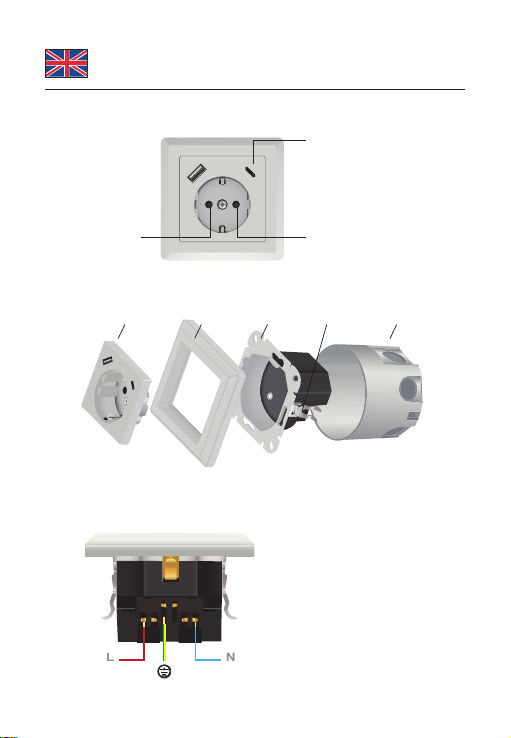
Layout
Childproof lock AC 250 V / 16.0 A
USB Charger:
Input:
AC 250 V / 50 Hz / 0.2 A
USB output:
max. 5.0 V / 3.4 A total
Installation Steps
Socket Cover Cover Module Installation Box
abcd e
Electrical Wiring Diagram
L
N
Live Wire
Protective Earth
PE
N
L
Neutral

-3-
English
Specication
• Connectors:
1 x power socket CEE 7/3 with childproof lock
1 x USB Type-A charging port
1 x USB Type-C™ charging port
3 x screw terminal for PE, N, L
• Rated current: 16.0 A / 250 V~
• Rated power: 4000.0 W
• USB Charger:
Input: AC 250 V / 50 Hz / 0.2 A
USB output: max. 5.0 V / 3.4 A total
Output power: max. 17.0 W total
Average active eciency 82.91 %
Eciency at low load (10 %) 78.09 %
No-load power consumption 0.095 W
Short circuit protection
• Suitable for switch series with 55 x 55 mm frame window size
• Mounting depth: 40 mm
• Suitable for standard installation box
• Claw and screw xing
• Fire retardant plastic housing (UL 94 V-0)
• Dimensions (LxWxH): ca. 80 x 80 x 44 mm
• Colour: white
System requirements
• Mains supply with grounding
• A free standard installation box
Package content
• Power socket
• User manual

-4-
English
Safety instructions
• This power socket is only suitable for indoor use (IP20).
• Use this power socket only in dry locations.
• The mounting and installation of electrical equipment is only
allowed to be carried out by a qualied electrician.
• This power socket provides a side grounding contact and
increased contact protection according to VDE0620. The
maximum allowed rated current is 16 A / 250 V~.
Installation
1. Connect the supply cable to the terminals according to the
Electric Wiring Diagram.
2. Put the module (b) into the installation box (e) and screw them.
If your installation box does not oer any possibility for screw
connection, use the clamps (a) on the right and left of the
module (b) to clamp the module.
3. Put the cover (c) onto the module (b) and insert the socket
cover (d) through the cover (c) onto the module (b).
4. Screw the cover (d) to the module (b).
Support Delock
If you have further questions, please contact our customer support
Final clause
Information and data contained in this manual are subject to change
without notice in advance. Errors and misprints excepted.
Copyright
No part of this user manual may be reproduced, or transmitted
for any purpose, regardless in which way or by any means,
electronically or mechanically, without explicit written approval of
Delock.
Edition: 09/2021

-5-
Deutsch
Systemvoraussetzungen
• Netzzuleitung mit Schutzleiter
• Eine freie Einbaudose
Packungsinhalt
• Einbausteckdose
• Bedienungsanleitung
Sicherheitshinweise
• Diese Steckdose ist nur für den Innenbereich geeignet (IP20).
• Verwenden Sie diese Steckdose ausschließlich an trockenen
Standorten.
• Die Montage und Installation von elektrischen Geräten darf nur
durch eine Elektrofachkraft vorgenommen werden.
• Diese Steckdose ist mit einem Schutzkontakt und einem erhöhten
Berührungsschutz gemäß VDE0620 ausgestattet. Der maximal
zulässige Nennstrom beträgt 16 A / 250 V~.
Installation
1. Schließen Sie die Zuleitung entsprechend dem
Anschlussdiagram (Electric Wiring Diagram) an die
Schraubklemmen an.
2. Stecken Sie die Steckdose (b) in die Einbaudose (Installation
Box) und schrauben Sie diese fest. Sollte ihre Einbaudose (e)
keine Möglichkeit für die Verschraubung bieten, klemmen Sie
die Steckdose mit Hilfe der Klammern (a) recht und links in der
Einbaudose (e) fest.
3. Legen Sie nun den Abdeckrahmen (c) auf die Steckdose
(b) und stecken Sie die Steckdosenabdeckung durch den
Abdeckrahmen (c) auf die Steckdose (b).
4. Schrauben Sie die Steckdosenabdeckung (d) an der Steckdose
(b) fest.

-6-
Français
Conguration système requise
• Alimentation électrique avec terre
• Un boitier standard d’installation
Contenu de l’emballage
• Prise de courant
• Mode d’emploi
Instructions de sécurité
• Cette prise de courant n’est appropriée que pour l’usage à
l’intérieur (IP20).
• N’utiliser cette prise de courant que dans des endroits secs.
• Le montage et installation d’un équipement électrique ne peut être
réalisé que par un électricien qualié.
• Cette prise de courant est munie d’un contact latéral de terre et
augmente la protection de contact selon le VDE0620. Le courant
maximum permis est de 16 A / 250 V~.
Installation
1. Connecter le câble d’alimentation aux bornes selon le Schéma
de câblage électrique (Electric Wiring Diagram).
2. Mettre le module (b) dans le boitier d’installation (e) et les
visser. Si votre boitier d’installation n’ore pas la possibilité
de connexions vissées, utiliser les gries (a) sur la droite et la
gauche du module (b) pour xer le module.
3. Mettre le capot (c) dans le module (b) et insérer le capot de
prise (d) dans le capot (c) du module (b).
4. Visser le capot (d) au module (b).

-7-
Español
Requisitos del sistema
• Red eléctrica con puesta a tierra.
• Una caja de instalación estándar gratuita
Contenido del paquete
• Tomacorriente
• Manual del usuario
Instrucciones de seguridad
• Este tomacorriente solo es adecuada para uso en interiores (IP20).
• Utilice este tomacorriente solo en lugares secos.
• Solo un electricista calicado puede realizar el montaje e
instalación de equipos eléctricos.
• Este tomacorriente proporciona un contacto de conexión a tierra
lateral y una mayor protección de contacto de acuerdo con
VDE0620. La corriente nominal máxima permitida es de
16 A / 250 V~.
Instalación
1. Conecte el cable de alimentación a los terminales de acuerdo
con el Diagrama de Cableado Eléctrico (Electric Wiring
Diagram).
2. Ponga el módulo (b) en la caja de montaje (e) y atorníllelos. Si
su caja de montaje no ofrece ninguna posibilidad de atornillar,
utilice las abrazaderas (a) a la derecha e izquierda del módulo
(b) para sujetar el módulo.
3. Coloque la tapa (c) en el módulo (b) e introduzca la tapa del
zócalo (d) a través de la tapa (c) en el módulo (b).
4. Atornille la tapa (d) al módulo (b).

-8-
České
Systémové požadavky
• Napájecí přívod s uzemněním
• Volná standardní instalační krabice
Obsah balení
• Napájecí zásuvka
• Uživatelská příručka
Bezpečnostní pokyny
• Tato napájecí zásuvka je vhodná jen pro použití v interiéru (IP20).
• Tuto napájecí zásuvku používejte jen v suchu.
• Montáž a instalaci elektrického vybavení smí provádět jen
kvalikovaný elektrikář.
• Tato napájecí zásuvka poskytuje boční zemnicí kontakt a
zvýšenou ochranu kontaktů podle normy VDE0620. Maximální
povolený jmenovitý proud je 16 A / 250 V~.
Instalace
1. Podle schématu elektrického zapojení (Electric Wiring
Diagram) připojte přívodní kabel ke svorkám.
2. Vložte modul (b) do instalační krabice (e) a přišroubujte jej.
Jestliže Vaše instalační krabice nenabízí žádnou možnost
šroubového spojení, použijte k uchycení modulu upínek (a) na
pravé a levé straně modulu (b).
3. Vložte kryt (c) do modulu (b) a vložte kryt zásuvky (d) skrze
kryt (c) na modul (b).
4. Přišroubujte kryt (d) k modulu (b).

-9-
Polsku
Wymagania systemowe
• Zasilanie z uziemieniem
• Puszka znormalizowana w cenie pakietu
Zawartość opakowania
• Gniazdo zasilania
• Instrukcja obsługi
Instrukcje bezpieczeństwa
• Gniazdo tylko do zastosowania w pomieszczeniach (IP20).
• Gniazdo do pracy w suchym otoczeniu.
• Tylko uprawniony elektryk może instalować urządzenia
elektryczne.
• Gniazdo zasilania ma styl do uziemienia i ochronę zgodną z
VDE0620. Dopuszczalne obciążenie 16 A / 250 V~.
Instalacja
1. Podłączyć kabel o zaciski zgodnie ze schematem (Electric
Wiring Diagram).
2. Moduł włożyć do puszki i przykręcić. Jeżeli puszka nie ma
otworów na wkręt, można użyć blaszek rozporowych (a) po
obu stronach modułu (b).
3. Założyć osłonę (c) na moduł (b) i wsunąć osłonę gniazda (d)
przez otwór aż do oparcia na module (b).
4. Dokręcić osłonę (d) do modułu (b).

-10-
Italiano
Requisiti di sistema
• Alimentazione di rete con messa a terra
• Una scatola d'installazione standard libera
Contenuto della confezione
• Presa di corrente
• Manuale utente
Istruzioni per la sicurezza
• Questa presa di corrente è adatta solo per uso interno (IP20).
• Utilizzare questa presa di corrente solo in luoghi asciutti.
• Il montaggio e l'installazione di apparecchiature elettriche deve
essere eseguito solo da un elettricista qualicato.
• Questa presa di alimentazione fornisce un contatto laterale di
messa a terra e una maggiore protezione dei contatti secondo
VDE0620. La corrente nominale massima consentita è di 16 A /
250 V~.
Installazione
1. Collegare il cavo di alimentazione ai morsetti secondo lo
Schema Elettrico (Electric Wiring Diagram).
2. Inserire il modulo (b) nella scatola di installazione (e) e avvitarli.
Se la scatola di installazione non ore alcuna possibilità di
collegamento a vite, utilizzare i morsetti (a) a destra e a sinistra
del modulo (b) per ssare il modulo.
3. Collocare il coperchio (c) sul modulo (b) e inserire il coperchio
della presa (d) attraverso il coperchio (c) sul modulo (b).
4. Avvitare il coperchio (d) al modulo (b).
Table of contents
Languages:
Other DeLOCK Accessories manuals


