DeLonghi EUROCHEF - PRO User manual

1
Air-2
EUROCHEF - PRO WALL HOOD
INSTALLATION INSTRUCTIONS
Shown with accessory Duct Cover Kit and accessory Warming Lamp Kit
APPROVED FOR ALL RESIDENTIAL APPLIANCES
FOR RESIDENTIAL USE ONLY
PLEASE READ ENTIRE INSTRUCTIONS BEFORE PROCEEDING.
INSTALLATION MUST COMPLY WITHALL LOCAL CODES.
IMPORTANT: Save these Instructions for the Local Electrical Inspector’s use.
INSTALLER: Leave these Instructions with this unit for the owner.
OWNER: Retain these instructions for future reference.
SAFETY WARNING
Turn off power circuit at service panel and lock out panel
before wiring this appliance.
REQUIREMENT: 120VAC, 60 Hz. 20A Branch Circuit
READ AND SAVE THESE INSTRUCTIONS
3
2
TIMER
1
EUROCHEF - PRO WALL HOOD
EUROCHEF U.S.A.
41 MERCEDES WAY SUITE 25 EDGEWOOD NEW YORK 11717 – TEL. 866-844-6566
WWW.DELONGHIMAJORAPPLIANCES.COM
WWW.DELONGHI RANGES.COM

2Air-2
EUROCHEF - PRO WALL HOOD
HOODS WEIGHT MODEL NUMBER
24” range hood with 600 CFM blower 22 lbs ECPH24S
30” range hood with 600 CFM blower 30 lbs ECPH30S
36” range hood with 600 CFM blower 36 lbs ECPH36S
48” range hood with 1200 CFM blower 48 lbs ECPH48S
ACCESSORIES MODEL NUMBER
WARMING LAMP KIT
Includes 175W Warming Lamps, rocker switches, quick connect wiring. Field installable.
24”/30” Warming Lamps Kit: (1) 175W Warming Lamp EC LAMP24/30
36” Warming Lamps Kit: (2) 175W Warming Lamp EC LAMP36
48” Warming Lamps Kit: (2) 175W Warming Lamp EC LAMP48
BACKSPLASH WITH WARMING SHELVES KIT
Includes telescoping 2-piece backsplash, removable & dishwasher safe shelves
24” Backsplash with (1) shelf EC BKSPL24
30” Backsplash with (1) shelf EC BKSPL30
36” Backsplash with (2) shelf EC BKSPL36
48” Backsplash with (2) shelf EC BKSPL48
RECIRCULATING KIT
Includes 4” high duct cover, 90 degree transition, charcoal filters
NOTE: Do not use with indoor BBQ. Do not use with Blower Upgrade Kit (below).
24” Recirculating Kit EC DLK24
30” Recirculating Kit EC DLK30
36” Recirculating Kit EC DLK36
Not Available for 48” Hoods
REPLACEMENT CHARCOAL FILTER
For use with Recirculating Kit Only Includes 2 Sets of Filters EC FILT
BLOWER UPGRADE KIT
Kit for 30” and 36” hoods only. Includes 600 CFM blower.
Not for use with Recirculating Kit or horizontal ducting EC BLMT
DUCT COVER 6”
Stackable 304 stainless steel.
24” wide 6” high duct cover EC CVR246W
30” wide 6” high duct cover EC CVR306W
36” wide 6” high duct cover EC CVR366W
48” wide 6” high duct cover EC CVR486W
DUCT COVER 12”
Stackable 304 stainless steel.
24” wide 12” high duct cover EC CVR2412W
30” wide 12” high duct cover EC CVR3012W
36” wide 12” high duct cover EC CVR3612W
48” wide 12” high duct cover EC CVR4812W
FEATURES
Controls: 4-speed electronic with 15” minute delayed shutoff
timer
Fabrication: Welded, polished and brushed seams
All edges hemmed
Features: 304 stainless hood baffle filter and grease tray
12V halogen lighting, lamps included
Top and Back ducting 24”, 30”, 36” hoods
Transition to 8” round with damper included
Install to wall or cabinets

3
Air-2
EUROCHEF - PRO WALL HOOD
CONSIDERATIONS BEFORE
INSTALLING HOOD
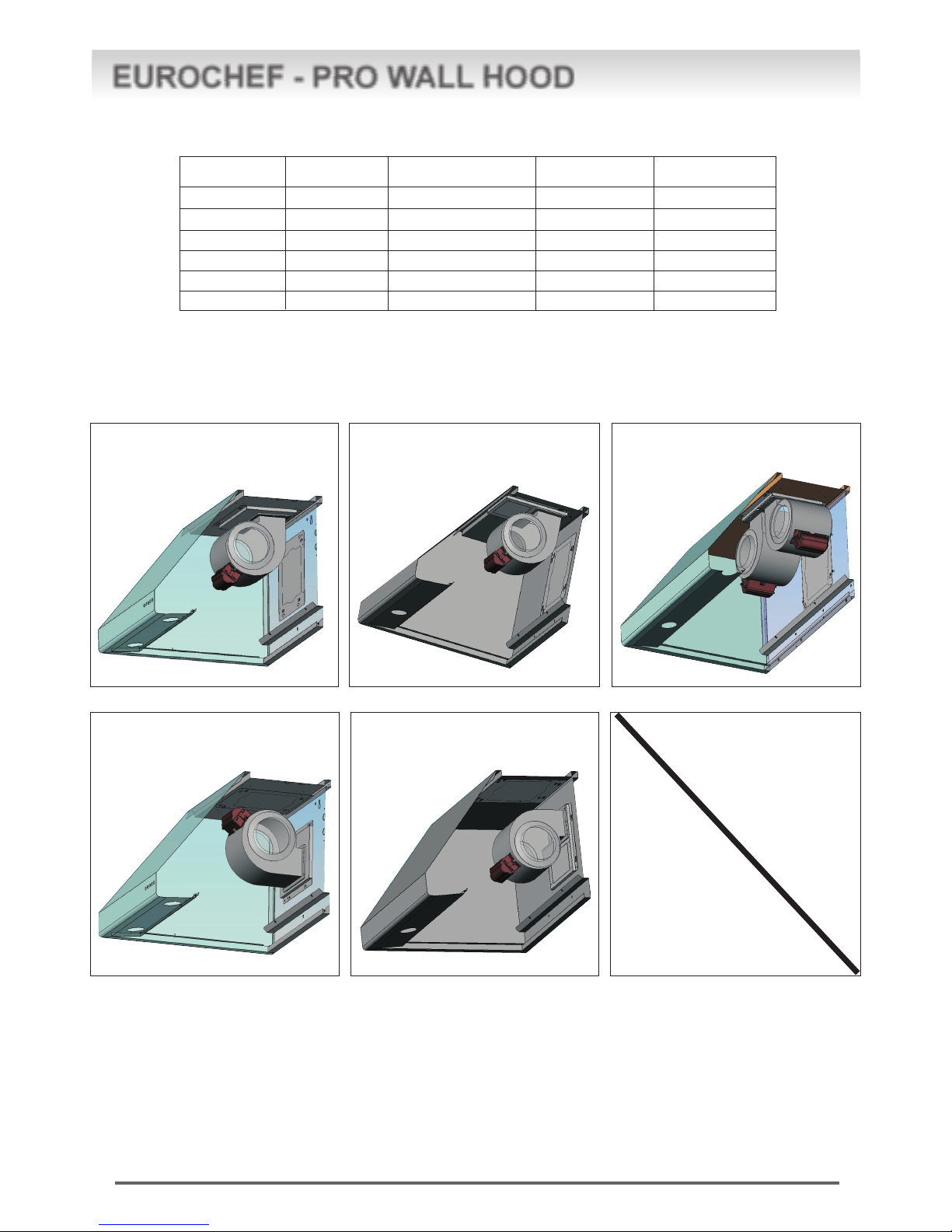
1. For the most efficient air flow exhaust, use a straight run or as few
elbows as possible.
2. Do not use flex ducting use metal ductwork only to reduce the risk
of fire.
3. COLD WEATHER installations should have an additional backdraft
damper installed to minimize backward cold air flow and a nonme-
tallic thermal break to minimize conduction of outside tempera-
tures as part of the ductwork. The damper should be on the cold air
side of the thermal break. The break should be as close as pos-
sible to where the ducting enters the heated portion of the house.
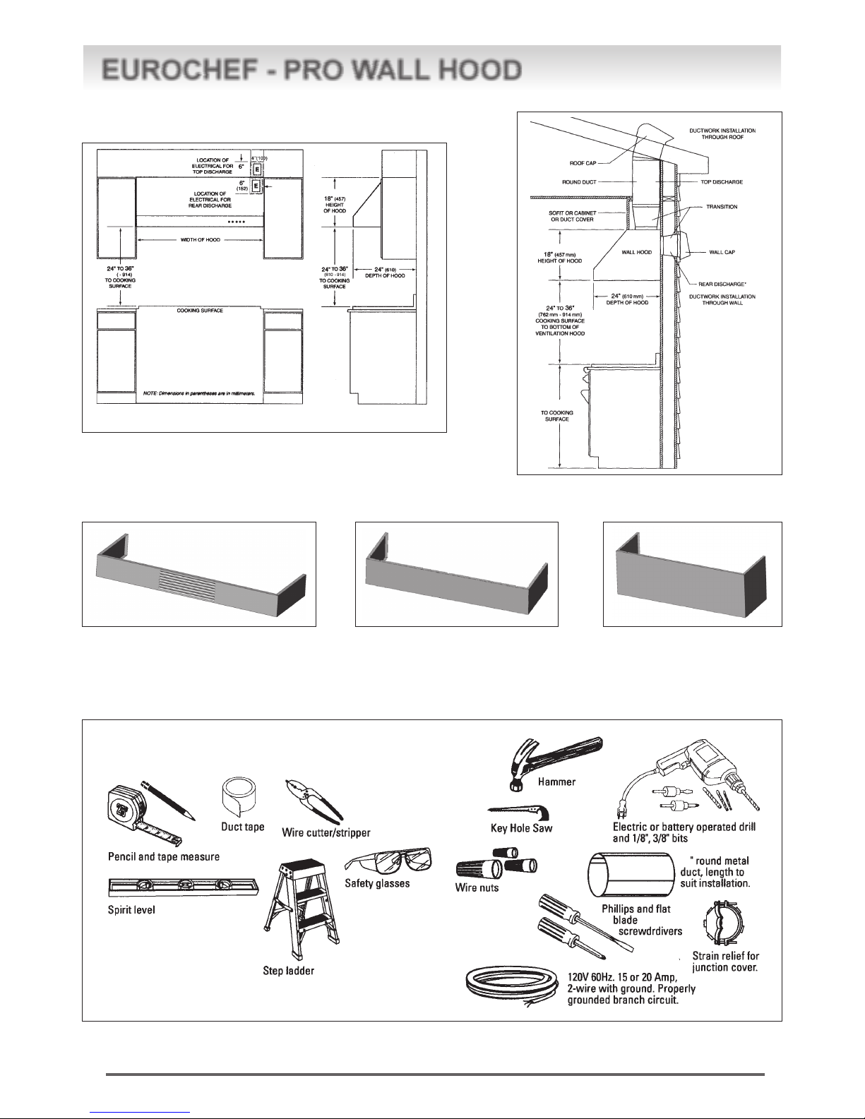
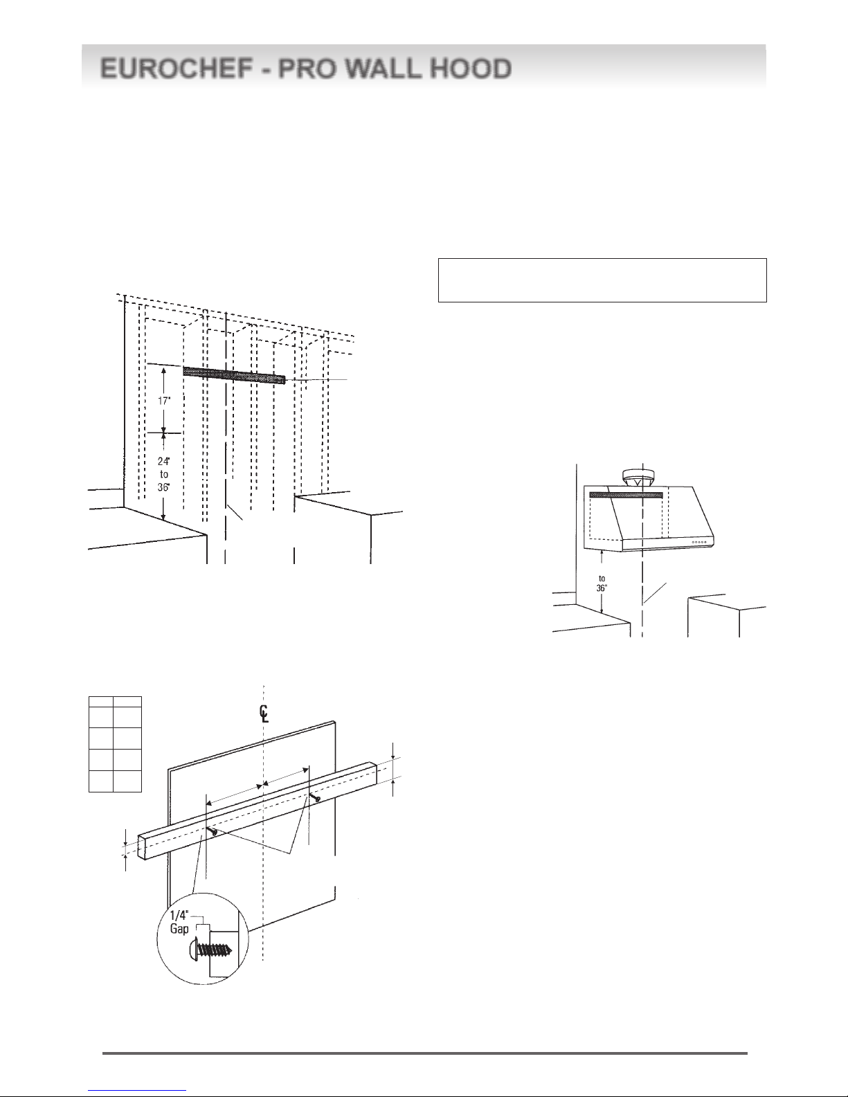
4. Hood installation height above cooktop is the users preference.
The lower the hood above the cooktop, the more efficient the cap-
turing of cooking odors, grease, and smoke. This hood has been
approved for installations as low as 24 inches* above the cooktop.
The lower height may be inconvenient for tall people and large
cooking vessels. Consequently, The manufacturer recommends
the hood be installed 30-to-36 inches above the countertop.
*For indoor grill installations, The manufacturer recommends a mini-
mum of 30" clearance.
5. Make-Up Air: Local building codes may require the use of make-
up air systems when using ducted ventilation systems greater
than specified CFM of air movement. The specified CFM varies
from locale to locale. Consult your HVAC professional for specific
requirements in your area.
6. Skill Level - Installation of this vent hood requires basic mechani-
cal and electrical skills.
7. Completion time- 1 to 3 hours.
8. Proper installation is the responsibility of the installer.
9. Product failure due to improper installation is not covered under the
Warranty.
CAUTION:
To reduce risk of fire and to properly exhaust air, be sure to duct
air outside - Do not vent exhaust air into spaces within walls or
ceilings or into attics, crawl spaces, or garages.
PRUDENCE:
Il faut prendre soin d’installer tul conduit vers l’extérieur pour
réduire le risque d’incendie et pouvoir évacuer l’air correctement.
Il ne faut pas évacuer l’air correctement. Il ne faut pas évacuer
l’air dans l’espace entre les parois d’un mur, un plafond ou un
grenier, un espace sanitaire ou ou garage.
WARNING:
Any such alteration from original factory wiring could result in
damage to the unit and/or create an electrical safety hazard.
ADVERTISSEMENT
Toute modification de ce type du branchement d’usine pente
endommager l’appareil ou créer un risque de choc électrique.
WARNING
TO REDUCE THE RISK OF FIRE, ELECTRICAL SHOCK
OR INJURY TO PERSONS, OBSERVE THE FOLLOWING:
A. Use this unit only in the manner intended by the manufac-
turer. If you have any questions, contact the manufacturer.
B. Before servicing or cleaning unit, switch power off at the
service panel and lock service panel to prevent power
from being switched on accidentally. If the service panel
cannot be locked, fasten a tag or prominent warning la-
bel to the panel.
• For general ventilating use only. Do not use to exhaust
hazardous or explosive materials or vapors.
• Structural framing, installation work and electrical wiring must
be done by qualified person(s). In accordance with all appli-
cable codes and standards including tire-rated construction.
• Sufficient air is needed for proper combustion and ex-
hausting of gases through the flue (chimney) of fuel burn-
ing equipment to prevent back drafting. Follow the heat-
ing equipment manufacturer’s guideline and safety stan-
dards such as those published by the National Fire Pro-
tection Association (NFPA), and the American Society
for Heating, Refrigeration and Air Conditioning Engineers
(ASHRAE), and the local code authorities.
• Local codes vary. Installation electrical connections and
grounding must comply with applicable codes. In the
absence of local codes, the vent should he in-stalled in
accordance with National Electrical Code ANSI/NFPA 70-
1990 or latest edition.
ADVERTISSEMENT
POUR RÉDUIRE LE RISQUE D’INCENDIE, DE CHOC
ÉLECTRIQUE OU DE BLESSURES, IL FAUT OBSERVER
LES REGLES SUIVANTES:
A. Utiliser cet appareil uniquement de la maniére prévue par le
fabricant. En cas de question, consulter le fabricant.
B. Avant toute intervention ou nettoyage, couper l’alimentation
électrique au disjoncteur et verrouiller le panneau du disjoncteur
pour éviter la mise sous tension accidentelle. S’il n’est pas
possible de verrouiller le panneau du disconcteur, attacher un
placard ou une étiquette trés visible au panneau.
• For general ventilating use only. Do not use to exhaust hazard-
ous or explosive materials or vapors.
• Structural framing, installation work and electrical wiring must
be done by qualified person(s). In accordance with all appli-
cable codes and standards including tire-rated construction.
• Sufficient air is needed for proper combustion and exhausting
of gases through the flue (chimney) of fuel burning equipment
to prevent back drafting. Follow the heating equipment
manufacturer’s guideline and safety standards such as those
published by the National Fire Protection Association (NFPA),
and the American Society for Heating, Refrigeration and Air
Conditioning Engineers (ASHRAE), and the local code au-
thorities.
• Local codes vary. Installation electrical connections and ground-
ing must comply with applicable codes. In the absence of
local codes, the vent should he in-stalled in accordance with
National Electrical Code ANSI/NFPA 70-1990 or latest edition.
READ THESE INSTRUCTIONS COMPLETELY AND CAREFULLY

4Air-2
EUROCHEF - PRO WALL HOOD
CONTENTS AND PAGE NUMBER
Product Dimensions....................................................... pg.4
Advance Planning...........................................................pg.5
Using Duct Cover Accessories........................................ pg.5
Tools and Materials Required ......................................... pg.5
Remove the packaging................................................... pg.6
Parts Provided............................................................... pg.6
Step 1: Determine Ductwork and Wiring Locations............ pg.7
Step 2: Prepare hood for installation................................. pg.7
Step 3A: Install Hood Onto Wall...................................... pg.10
Step 3B: Install Hood Beneath Sofit or cabinet................. pg.11
Step 4: Connect Ductwork ............................................ pg.12
Step 5: Connect Electrical ............................................ pg.12
Step 6: Install Duct Covers ........................................... pg.12
Step 7: Tighten hanging screws .................................... pg.13
Step 8: Re-Install the Filter Frame ................................. pg.13
Step 9: Install Grease filter trays + filters ........................ pg.14
Step 10: Test hood ...................................................... pg.14
Care and use instructions ............................................ pg.15
PRODUCT DIMENSIONS
3
2
TIMER
TIMER
1
18”
24”
24”- 30”- 36”- 48”

5
Air-2
EUROCHEF - PRO WALL HOOD
Cabinetry and electrical placement for 24-inch deep wall hoods. lnstallatian
dimensions
for 24 deep
wall hoods.
ADVANCE PLANNING
USING DUCT COVER ACCESSORIES
To avoid gaps, plan the hood installation height for duct cover use.
Recirculating Kit Cover 4” (if used) Duct cover 6” Duct cover 12”
1. Duct covers and Recirculating Kit covers are stackable.
2. The hood is 18” tall and can be installed from 24” to 36” above cooking surface (30” to 36” is optimum).
3. Locate hood so that duct covers and Recirculating Kit Cover (If used) leave no gap between hood and ceiling.
8
TOOLS AND MATERIALS REQUIRED (NOT SUPPLIED)
36” (914 mm)
This manual suits for next models
4
Table of contents
Other DeLonghi Ventilation Hood manuals
Popular Ventilation Hood manuals by other brands

Gorenje
Gorenje S3 IHGC963S4X manual

KOBE
KOBE ISX2136SQB-1 Installation instructions and operation manual

U.S. Products
U.S. Products ADVANTAGE-100H Information & operating instructions

Kuppersberg
Kuppersberg DUDL 4 LX Technical Passport

Framtid
Framtid HW280 manual

Thermador
Thermador HGEW 36 FS installation manual