Delptronics WiiChuck User manual

WiiChuck Kit Instructions Page 1 of 6
Important Information
Congratulations and thank you for your purchase of the
Delptronics WiiChuck module kit!
Once you have built the kit, download the User Manual
to learn how to use all of the features.
Before you start, please read the Electronic Kit
Soldering Tutorial. It contains important and useful
information even for experienced kit builders. This is a
good first electronic kit. It is relatively straightforward to
assemble, and there are not that many different parts.
Take your time and be careful to put the right part in the
right place, and, where applicable, in the right
orientation. It is difficult to de-solder parts if you make a
mistake.
The parts for the kit are in multiple bags. One or more
bags contain discreet components like resistors and
capacitors, and the other bag contains
electromechanical parts like jacks, and buttons. The
discreet components are soldered first. Before you start,
separate the parts by type. When you are ready to
solder parts of a particular type, separate them by
value. In general, the order that the parts are soldered
onto the PCB is shortest to tallest.
The complete bill of materials (parts list) is on the last
page of this document.
The PCB is marked with the part refdes (reference
designator), For example, R1 refers to resistor number
one and C1 refers to capacitor number one. In the case
of the resistors, the value is also printed on the PCB.
Refer to the picture of an assembled kit to the right for
guidance on part placement and orientation.
WiiChuck Kit Instructions Page 2 of 6
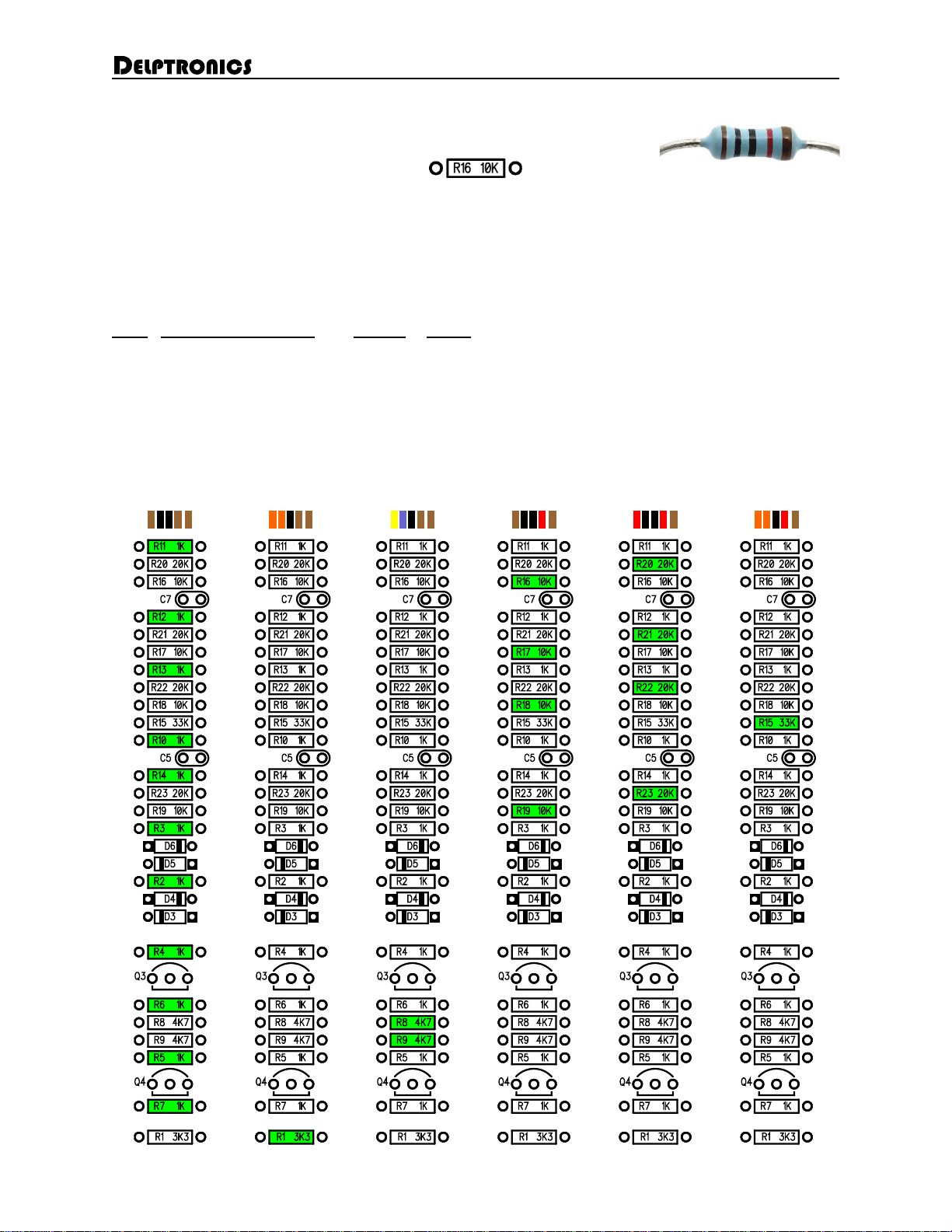
Resistors
The value of a resistor is indicated by colored stripes on its body. In all cases the fifth stripe is brown (indicating 1%
tolerance), so that stripe has been omitted from the chart below. In addition to the refdes, the resistor value is printed
right on PCB.
The resistor leads need to be bent close to the body of the resistor. Hold the resistor body and press down on each
lead right at the body to make a U shape. It does not matter which lead goes in which PCB hole.
Value Marking (colored stripes) Quantity Refdes
1K Brown, Black, Black, Brown 11 R2, R3, R4, R5, R6, R7, R10, R11, R12, R13, R14
3K3 Orange, Orange, Black, Brown 1 R1
4K7 Yellow, Violet, Black, Brown 2 R8, R9
10K Brown, Black, Black, Red 4 R16, R17, R18, R19
20K Red, Black, Black, Red 4 R20, R21, R22, R23
33K Orange, Orange, Black, Red 1 R15
Resistor Value Map

WiiChuck Kit Instructions Page 3 of 6
Diodes
There are 6 diodes. They are the same type (BAT85). The diodes are red and black glass tubes. When inserted into
the PCB, the black side of the diode must line up with the stripe on the part outline on the PCB. The diode leads need
to be bent close to the body of the diode. Hold the diode body and press down on each lead right at the body to make
a U shape.
Chip Sockets
There is one 8-pin socket and three 14-pin sockets. Sockets are marked with a small notch that must line up with the
outline on the PCB. Once the socket is soldered in place, the PCB outline will not be visible, so it is important that the
sockets are oriented correctly in order to ensure that the chips are inserted into the sockets correctly.
Note that two of the 14-pin sockets go right next to each other to accommodate the 28-pin U1.
Ceramic Capacitors
Ceramic capacitors are small tan or blue blobs. Their value is marked on them with a three-digit code. The marking is
rather tiny, so you may have to use a magnifying glass to read them. It does not matter which lead goes in which
PCB hole.
We recommend that you start with the 1 uF capacitor, because there is only one of them. The rest are all 0.1 uF.
Value Marking Quantity Refdes
0.1 uF 104 5 C4, C5, C6, C7, C8
1 uF 105 1 C3
Electrolytic Capacitors
Electrolytic capacitors look like a little tin can. There are two of them, and they are both the same value.
Electrolytic capacitors are polarized, so which lead goes in which hole is important. The negative lead on the
capacitor is the shorter one and it is indicated by gray stripe on the capacitor body. The positive lead is longer. The
positive hole on the PCB has a square pad and is marked with a plus sign.

WiiChuck Kit Instructions Page 4 of 6
Voltage Regulator
There is one voltage regulator (refdes REG1). It is marked KY5033. They have the same shape as a transistor, so
make sure that you look at the part marking to verify which one is the regulator,
Make sure that the flat side of the part lines up with the flat side of the outline on the PCB. Push the leads through the
holes, and bend the two outer leads apart to keep it in place while soldering. They will not sit flush against the PCB,
and that is fine. Do not force them.
Voltage regulators and transistors are more heat sensitive than most of the parts in this kit, so take care not to let the
soldering iron linger too long. If you are unsure, then solder one lead at a time and let the part fully cool off before
soldering the next lead.
Transistors
There are two 2N3904 transistors. They are marked on the PCB with refdes Q3 and Q4. There is no Q1 or Q2.
For soldering tips, refer to the paragraphs above relating to the voltage regulator.
Pushbutton
The pushbutton can only be inserted one way. The actuator (that you press) faces away from the PCB. It snaps into
place and will stay put while you solder it. Make sure it is fully inserted and seated flush against the PCB.
3.5mm Jacks
The eight 3.5mm jacks are inserted with their openings facing away from the PCB. The jacks do not snap in and will
not stay in place by themselves. Insert the jacks and flip the PCB over onto your work surface. They are the tallest
part on the PCB, so they will rest flat on your work surface. Solder only one pin of each jack. Then, check to make
sure each jack is flush against the PCB. If it is not flush, simply reheat the one solder joint while pressing the jack into
place. Once all jacks are all flush, go back and solder the other pins.

WiiChuck Kit Instructions Page 5 of 6
Power Header
The power header does not snap in and will not stay in place by itself. Insert the shorter pins into the PCB, and flip
the PCB over onto your work surface. Solder only one pin. Then, turn the PCB over and check to make sure that the
header is flush against the PCB. If it is not flush, simply reheat the one solder joint while pressing the header into
place. Once it is flush, go back and solder the other pins.
Chips
There are three chips, each one is a different size, so it is easy to find the right socket for
each chip. Carefully insert each chip into its appropriate socket, making sure not to bend any
of the pins. Note the direction of the chips before inserting them. The notch on the chip must
line up with the notch on the socket, which lines up with the notch printed on the PCB.
The pins of the chips come from the factory a little bit splayed out, not pointing straight down.
You may need to bend them inward a little before you insert them. Hold the body of the chip
and rest all of the pins on one side against the table top and gently press down just a little bit.
Then do the other side. If the pins do not line up well with the socket, repeat the straightening procedure.
Value Pins Quantity Refdes
PIC16F1778 24 1 U1
TL072 8 1 U2
TL074 14 1 U3
LED
The panel must be attached and the nuts screwed onto the jacks
before the LED can be installed.
Bend the LED’s leads at a 90° angle. The bend goes just below the
thicker part of the leads. The LED is polarized. The short lead goes in
the square PCB hole. Make note of the short lead before bending it.
Insert the leads into the PCB, push the LED through the panel, turn
the PCB upside down, and solder the leads.

WiiChuck Kit Instructions Page 6 of 6
Complete!
Congratulations! Your WiiChuck module is now assembled and useable.
Bill of Materials
Name
Value
Quantity
RefDes
Schottky Diode
BAT85
6
D1, D2, D3, D4, D5, D6
Resistor
1K
11
R2, R3, R4, R5, R6, R7, R10, R11, R12, R13, R14
Resistor
3K3
1
R1
Resistor
4K7
2
R8, R9
Resistor
10K
4
R16, R17, R18, R19
Resistor
20K
4
R20, R21, R22, R23
Resistor
33K
1
R15
Ceramic Capacitor
0.1uF
5
C4, C5, C6, C7, C8
Ceramic Capacitor
1uF
1
C3
Electrolytic Capacitor
10uF
2
C1, C2
NPN Transistor
2N3904
2
Q3, Q4
3.3V Regulator
LM7833
1
REG1
MCU
PIC16F1778
1
U1
Op Amp
TL072
1
U2
Op Amp
TL074
1
U3
LED
1
L1
Jacks
8
J1-J8
Pushbutton
1
PB1
8-pin Socket
1
14-pin Socket
3
10-Pin Power Header
1
PCB
1
Panel
1
Power Cable
1
Screws
4
Table of contents
Other Delptronics Control Unit manuals


Popular Control Unit manuals by other brands

Festo
Festo Compact Performance CP-FB6-E Brief description

Elo TouchSystems
Elo TouchSystems DMS-SA19P-EXTME Quick installation guide

JS Automation
JS Automation MPC3034A user manual

JAUDT
JAUDT SW GII 6406 Series Translation of the original operating instructions

Spektrum
Spektrum Air Module System manual

BOC Edwards
BOC Edwards Q Series instruction manual

KHADAS
KHADAS BT Magic quick start

Etherma
Etherma eNEXHO-IL Assembly and operating instructions

PMFoundations
PMFoundations Attenuverter Assembly guide

GEA
GEA VARIVENT Operating instruction

Walther Systemtechnik
Walther Systemtechnik VMS-05 Assembly instructions

Altronix
Altronix LINQ8PD Installation and programming manual


