preVent BR51 User manual

BR51 Instruction Manual

2
Manual Version 1.1 07.11.2019
INHALTSVERZEICHNIS
1.Functional principle
2.Installation
3.Operating conditions
4. Operability, maintenance and repair
5. Change valve configuration and control air range
6. Typical operating troubles and how to eliminate them
7. Safety conditions
8. Spare part list
9. Drawings
10.Contacting us
To ensure trouble-free and safe operation of the valve, it is essential to be familiar with the contents of this
BR51 Instruction Manual, and also with the general instructions for installation and operation, before installing
and operating the valve.
Failure to observe or comply with these operating instructions will invalidate the manufacturer’s guarantee and
liability. The manufacturer’s general conditions of sales and terms of delivery shall apply unless otherwise
stated.

3
Manual Version 1.1 07.11.2019
1. FUNCTIONAL PRINCIPLE
The valve regulates mass-flow by a linear movement of the valve spindle, which may be operated pneumatically, electrically
or manually. As the stroke of the valve alters, the circular gap between the valve seat and the valve block is increased or
reduced. This directly influences the amount of fluid flowing through the valve
2. INSTALLATION
The valve may be mounted in any position; however, for valves of DN 80 size and above, vertical installation with the drive
mounted above is preferred. For valves with extended construction, bellows, or drives weighing more than 50 kg, a suitable
support or suspension mounting should be provided for the drive, otherwise its own weight might cause wear and leakage at
the seals.
3. OPERATING CONDITIONS
Regulator valves should be operated under conditions that take into account the size and nature of the construction and the
type of material. To ensure trouble-free operation over the whole operational lifetime, the regulator valve and its accessories
should be regularly inspected and maintained.
Normal operating conditions:
a. With pneumatic positioning drive
- Ambient temperature from - 40 to +65 °C
- Relative humidity up to 98 %,
- Acceptable air supply fluctuation +/-10%
- The control and instrument air must be performed by Class 3 according to DIN ISO 8573-1.
The control and feed air supplies must contain no mechanical impurities, oil or corrosive substances, copper or aluminium
alloys, and must be dehumidified such that the dew-point corresponds to a temperature that is at least 10 °C lower than the
operating temperature of the position controller and the positioning drive.
b. With electrical positioning drive
- In accordance with the manufacturer’s instructions.
c. With hand-operated drives of type NN
- Ambient temperature from - 40 to +85 C
- Relative humidity up to 98 %,

4
Manual Version 1.1 07.11.2019
4. OPERABILITY, MAINTENANCE AND REPAIR
The operability of the regulator valve during use is based on maintaining an appropriate flow characteristic and not
exceeding the permitted leakage level for the valve
To ensure long-term correct and safe operation of the valve, it is essential to carry out regular recorded inspections. Valves
that operate continuously should be checked at least every 6 months. Valves that operate discontinuously should be
checked at least every 12 months.
If it is necessary to carry out maintenance or repair work on the regulator valve, it should be carried out as follows:
A key criterion for operability is external seal-tightness, which is provided by the gland packing.
The gland packing to be used is normally pre-specified based on the operating conditions.
With normal gland packing, the tightness of the seal is achieved by tightening the sealing nut.
WARNING:
When the valve is supplied, the sealing nut is only hand-tightened. Before putting the valve into service, it is
essential to tighten the sealing sufficiently to achieve an adequate contact pressure, thus ensuring a secure
external seal, but without blocking the valve spindle.
If self-adjusting sealing glands are used, the constant contact pressure is provided by a stainless steel spring. For this
reason, the sealing nut should be screwed in up to the stop.
4.1 Valve dismantling
For dismantling and cleaning the valve during periodical inspection carry out every time the following operations:
a) disconnect the conduit with actuator input signal and if it is necessary dismount the valve from the pipe. In case of
pneumatic actuator with positioner disconnect signal and supply
b)
Disconnect the plug stem from the stem of the actuator or driver in the following mode:
- In valves with pneumatic actuators or manual drives by unscrewing the union nut (27), having the low counter nut (28)
loosen first
- In valves with electric actuators by screwing out the valve stem from the connector by stem-plug unit rotating. Prior to
dismantling the actuator from the bellow bonnet, loosen up the screw plug (19) and nuts (62). While disconneting the stems,
pay special attention as not to overtighten the bellow
c) Unscrew nut (12) which fasten the actuator or manual driver and than disconnect it from the connecting plate
d) Unscrew nuts (9) and dismount bonnet with steam and plug
e) Clean the valve seat and valve plug sealing faces and clean inside the valve body
f) make sure that the valve seat sealing face (2) and valve plug face (4) ,the valve plug guide face and Stem guide face and
body gasket (6) are in satisfactory condition

5
Manual Version 1.1 07.11.2019
4.2 Lapping the valve seat and plug
In case of excessive leaks of closed valve it is necessary to grind in the valve seat and valve plug faces. To do it, dismount
the valve and carry out the following operation:
a) Loose the packing pressure
b) Apply a thin and uniform coat of lapping paste to the valve seat face and remount the bonnet with the valve plug and
valve stem on the valve body fasting it slightly in position by two nuts on the opposite sides of the bonnet
c) Lap the valve seat and valve plug faces by turning the stem by hand several times in either direction through the angle of
45 pressing slightly the valve plug against the valve seat.
d) Raise the valve plug, turn it through 30, lower it cautiously into the valve seat and repeat the operations as per item b).
e) Repeat these operations several times until the valve plug is turned round.
f) After the lapping completion clean the valve seats and valve plug thoroughly from lapping paste remnant using extraction
naphtha and inspect the valve faces condition.
g) Assemble the valve together with actuator according to the mode of its operation as per item 4.6.
h) Adjust the packing pressure according item 4.5.2.
Warning!
1. The lapping should be done carefully using small amounts of lapping paste and avoiding local scratches or indents to be
made. It should be remembered that excessive or strong pressing down will make the faces worse.
2. Due to the possibility of damage to the bellow, the lapping of the plug at the bellows bonnet should be performed by the
service team of a manufacturer.
4.3 The valve seat replacement
If is impossible the valve seat to grind in on account of their excessive wear or when we notice that the overlapping ring
(PTFE/silicone rubber) at tighten seat is broken the seats should be replaced.
In this situation having the valve dismantled as per item 4.1, should be done the following activities:
a) Unscrew the valve seat using a special spanner to seats. After having unscrewed the valve seat clean thoroughly the
threads and valve body inside.
b) Prior to screwing new valve seat apply to the threads a thin uniform coat of sealing compound which also protects the
valve seats against turning during operation. After pressing home the valve seat remove the excess of the sealing
compound
.

6
Manual Version 1.1 07.11.2019
4.4 The valve plug replacement
In case of excessive wear of valve scaling plug face or erosion of its shaped part, the valve plug should be replaced
.
4.4.1 The valve plug replacement at valve with standard or extension bonnet
The valve plug replacement can be done after valve dismounting according item 4.1 and loosing of the packing pressure and
it should be done depending on Kvs valve, in the following way.
a) For Kvs=1,6...16; Kvs=63...630 (for DN 150...200) as well as Kvs = 0,01...1
(for extension and bellows bonnet):
- Knock out the pin (8) using a drift and than unscrew the plug
- Screw the new plug with stem and lock with the pin
- Insert the stem plug into bonnet, paying attention to don't damage the packing (the package packing and packing ring at
balanced plug).
b) For Kvs=25...160 (for DN40...100):
- Unscrew the stem from the plug and remove the conical insert (8),
- Put the conical insert onto the stem and screw the new plug
- Insert the stem plug into bonnet, paying attention to don't damage the packing (the package packing and packing ring at
balanced plug)
After replacement the bonnet screw (20) should be preliminary screwed and the actuator should be mounted final
adjustment packing pressure should be done according item 4.5.2
4.4.2 Plug replacement in valve with bellows bonnet
The valve plug replecement can be done after valve dismounting as per item 4.1 and loosing of the packing pressure and it
should be done in the following way; depending on Kvs valve:
a) For Kvs=25...160 (for DN 40...100):
- Unscrew the plug from stem holding it means of flat wrench, paying special attention not over tighten the bellows; remove
conical insert
- Put the conical insert into the new plug and screw it to the stem, as described above
b) For the remaining Kvs valves:
- Knock out the pin (8) using drift and unscrew the plug as described in a) above
- Screw the new plug with stem and lock with a pin; secure the stem against rotation
After replacement the bonnet screw (20) should be preliminary screwed and the actuator should be mounted final
adjustment packing pressure should be done according item 4.5.2

7
Manual Version 1.1 07.11.2019
4.5 Packing replacement
4.5.1 Packing replacement at valve bonnet
When the single gasket completing at bonnet don't give the result or when is necessary change type of packing than is
necessary change packing package.
In this situation after dismounting the valve (item 4.1) the following activities should be done:
a) Put out the valve stem from the bonnet
b) Undo nut and take out the resistant rings, packing and sleeves
c) Clean the bonnet inside
d) Insert the valve stem to bonnet.
e) Take in new seal set and other elements at right sequence inside the bonnet
f) Press the gasket using the screw plug and assemble the valve in opposite sequence of operation
Attention!
1) In order to facilitate the replacement of singular packing rings we recommend to buy suitable tools.
2) Final adjustment packing pressure should be done during starting up repaired valve. After preliminary packing pressure
can occur small leakage. It can be done away with screwing the nuts at this way to eliminate the leakage but not increase
to much the stem resistance. In case of packing type „V” the nut should be done maximally.
4.5.2 Gaskets replacement in valve body and bellows and extension bonnets.
In case of a visible wearing out of body gasket (15) or bonnet packing in bellows bonnet (87, 93, 95), they should be
replaced. Gaskets and packing materials should be suitable for working parameter of the valve and fluid type

8
Manual Version 1.1 07.11.2019
4.6 Valve montage
4.6.1 Valves with pneumatic actuator and this function:
Air increase
-
Valve
CLOSE
(
Type
P)
a) Insert bonnet with connecting plate, plug, stem and body gasket (6) into valve.
b) Screw nuts (9) which connecting bonnet tight.
c) Displace the steam with plug in this way that plug will take right place at the seat.
d) Put the actuator on the connecting plate and screw lightly two nuts (12) with flat washer (13) and elastic washers (14)
e) Supply control air and make stem perform the whole stroke
f) Connect and block the valve steam with the actuator stem by using block nut.
g) Adjust the stroke plate in position of closed valve
h) Strongly screw the clamp nut which fasten the actuator to the connecting plate
i) Decrease the control air up to zero. The stroke plate should show the position of open valve. If necessary, connect the
stroke by undoing the clamp nut and adjusting the block nut
4.6.2 Valves with pneumatic actuator and this function:
Air increase
-
Valve OPEN
( Type
R )
a) Make valve montage according item 4.6.1 a....d
b ) Connect the valve steam with the actuator stem by using the clamp and block nut..
c) Adjust the stroke plate in position of closed valve
d) Supply control air and make stem displacement for full stroke.
e) Undo the connecting nut and push away steam and actuator (about 0,6 mm away) by half rotation of the block nut; and
then block the both stems
f ) Strongly screw the clamp nut which fasten the actuator to bonnet
g) Decrease the control air up to zero and make stroke plate position correction. The plug should be pressed against the
seat with a force equal to preliminary spring tension.

9
Manual Version 1.1 07.11.2019
4.6.3 Valves with electric actuator
a) Insert bonnet with connecting plate, plug, stem and body gasket into valve body. And then screw double nut (80) at stem.
b) Screw nut which connecting bonnet tight
c) Put on the actuator (with stem at position closed "Z") at the connecting plate
d) Connect the valve stem with the actuator stem by screwing the valve stem to connector (79) until the column will be
seated at the connecting plate
e) Block the bonnet by double nut.
Attention!
While connecting the valve with bellows bonnet, a special attention should be paid as not to over tighten the bellow.
Connecting should be done in the following way:
Undo the screw plug (19) tighten packing and nuts (62), which fasten the bonnet;
f ) Do the nuts with elastic washers, witch fasten the actuator to the connecting plate
g) The stroke plate should indicate position of the fully closed valve
h) Connect the tubing and supply the actuator as described in the instructions
i) Correct the stroke, if necessary, by adjusting limit switches
4.6.4 Valves with manual drive type LNN
a) Make valve montage according item 4.6.1 a....c
b) Put on the manual drive at the connecting plate and screw lightly the two nuts with elastic washers
c) Connect and block the valve steam with drive dog (78) by using clamp nut and block nut
d) Adjust the stroke plate in position of closed valve
e) Strongly screw the clamp nut which fasten the drive at the connecting plate
f) Make stroke correction by undo clamp nut and suitable re-setting the block nut

10
Manual Version 1.1 07.11.2019
4.7 Diaphragm replacement
4.7.1 Valves with pneumatic actuator and this function:
Air increase
-
Valve
CLOSE
(
Type
P)
a) Disconnect control air pipes from actuator.
b) Dismount upper actuator housing, paying special attention to undo tension nut at the end of operation: according the
remark at the safety tag.
c) Undo the special nut from the actuator stem and take off the distance ring.
d) Replace the diaphragm (42) and montage the actuator.
e) Connect the control air pipes
f ) supply pneumatic control signal;
4.7.2 Valves with pneumatic actuator and this function:
Air increase
-
Valve OPEN
( Type R )
a) Disconnect control air pipes from actuator.
b) Dismount upper actuator housing, taking special attention to undo tension nut (82) at the end of operation: according the
remark at the safety tag
c) Take off the springs (38).
d) Undo the special nut from the actuator stem and take off the diaphragm plate (43) together with spring limit sleeve (48)
e) Replace the diaphragm and montage the actuator.
f ) Connect the control air pipes
g) Supply pneumatic control signal;

11
Manual Version 1.1 07.11.2019
4.8 Pneumatic actuator bonnet seal unit replacement
To replace bonnet gasket unit (important for R type actuator) should be done:
a) Disconnect valve stem with actuator stem (according point 4.1 b) and take out position indicator,
b) Unscrew two nuts which fasten the actuator to connecting plate and take off the actuator from valve
c) Undo double screw from actuator stem together with position indicator
d) Dismount stems housing (83), unscrew bonnet unit and take off it from actuator stem, remembering or marking its initial
position
e ) Change worn out packing rings type "O" (34), (35)
f) Install bonnet unit to stem and screw in it to position before replacement
g) Install other elements on the actuator in opposite sequence than dismounting
5. CHANGE OF VALVE OPERATION AND CONTROL AIR RANGE
5.1 Change of operation in valve with pneumatic actuator
Reversible diaphragm pneumatic actuator type P/R construction gives possibility of changing valve operation from direct
action (air increasing close the valve) to reverse action (air increasing open the valve) and inversely.
To do it is necessary to change actuator operation; in this way should be done:
a) Dismount connection of valve stem with actuator stem
b) Maximally screw-in the bonnet (in direct actuator) or unscrew the bonnet till the packing ring type „O” shows up (in the
reverse actuator) in order to reduce initial spring tension
c) Dismount actuator upper housing remembering that tension nuts should be unscrewed at the end according remark on
the safety plates
Next activity depend on actuator operation before change
In order to change actuator operation from P (direct action) to R (reverse action) you should:
d) Undo special nut from actuator stem
e) take off the diaphragm together with diaphragm plate, distance ring, washer, distance sleeve (or distance sleeves at 630
and 1000 actuator) remembering about stem protecting from coming out from bonnet unit
f ) Take out the spring from bottom housing
g) Turn around the diaphragm for 180°and put on it at the actuator stem
h) Screw on the special nut at the actuator stem tightening at the same time the whole unit
i) Put on the springs at the diaphragm plate in this way that they take right place at the pilot stamping and their ends will be
at the same position in relation to stem axis

12
Manual Version 1.1 07.11.2019
j) Put on the upper housing at the spring and at first screw on tension springs and steady press the springs up to receiving
contact upper and bottom housing and than place other screws and screw on by nuts both side of housing
k) Set the initial spring tension by rotating the bonnet, connect the stems and reset the whole actuator
In order to change actuator operation from R (reverse action) to P (direct action) you should:
l) Take off springs from diaphragm plate
m) Undo special nut from actuator stem
n) Take off the diaphragm together with diaphragm plate, distance ring, washer, and distance sleeve (or distance sleeves at
630 and 1000 actuator) remembering about stem protecting from coming out from bonnet unit.
o) Put on the springs at the market places at the bottom housing
p) Turn around the diaphragm for 180°and put on it at the actuator stem in this way that the whole Ø6 on the bottom and
groove at the diaphragm plate edge was at the axis of one of the holes in diaphragm rim
q) Screw on the special nut at the actuator stem tightening at the same time the whole unit
r) Put on the diaphragm unit at the spring in this way that they take right place at the pilot stamping in the diaphragm plate.
To check that springs are at the right position, bend aside the diaphragm (in place of groove incision at the diaphragm plate
edge) up to uncovering the whole 6 at the diaphragm plate bottom and observe if under it is spring
s) Put on the upper housing at the stem forehead plane and at first screw on tension springs and steady press the springs
up to receiving contact upper and bottom housing and than place other screw and screw on by nuts both side of housing
t) Set the initial spring tension by rotating the bonnet, connect the stems and reset the whole actuator.

13
Manual Version 1.1 07.11.2019
5.2
Change of operation in handwheels for pneumatic actuators
In case of changing the operation from P to R in pneumatic actuators equipped with handwheels it is also necessary to
change the handwheel operation.
Thanks to handwheels universal design, it is necessary to change only the connection with actuator. The connecting
element between the actuator stem and handweel driver is the special nut (34), which in fact forms the part of actuator
where it performs the function of the assembly clamp for the diaphragm unit (diaphragm, diaphragm plate, distance sleeve,
washer, distance ring). The mounting of the special nut should be done in the following way:
a) by actuators with direct function (P)
* screw the special nut at the actuator stem so that its flange (bigger diameter) with milling faces for wrench should be
positioned at the lower part. The driver, through its hole in the lower part sits on the smaller diameter of the special nut and
lining against its flange pushes the actuator stem and diaphragm down.
b) by actuators with reverse function (R)
* The special nut should be inserted into the driver (through one of the clearings made by milling its face) so that its flange
(bigger diameter) is positioned the upper part (it means that the special nut is turned down at 180O in comparison to its
position in direct actuators). Then turn the special nut in such a way that its milling face should cover the drives milling. Then
screw it along with the driver at the actuator stem by means of a flat wrench. The lug in the drives hole should line against
the flange of the special nut and puch the actuator stem and diaphragm up
Attention !
*
During automatic operation of the actuator with handwheel, the handweel should be at its limit
position:
a) Top – by direct actuators PN (turn the handwheel to the right)
b) Botton – by reverse actuators RN (turn the handwheel to the left)
*
I
n the automatic made of operation, the handwheel can act as the stroke limit for the valve plug during valve opening.

14
Manual Version 1.1 07.11.2019
6. TYPICAL OPERATING TROUBLES, THEIR CAUSES AND REMEDIES
LP
Trouble
Cause
Remedy
1 Excessive valve hysteresis
Ten packing of valve bonnet
are pressed down too strong Loosen the valve bonnet nuts
2 Valve plug dose not
perform the full stroke
Soiled face of valve plug
stem or actuator stem or plug
Clean the face of valve stem or
actuator (reversed) stem
Valve seats soiled with hard
particles Clean the valve
3 Valve lift is not
proportional to the current
Maladjustment of the joint
between valve plug stem and
actuator stem.
Readjust the joint between the
valve plug stem and actuator
stem. Set the initial tension of the
spring properly
4 The valve plug is put out
of action
Seizing of the valve plug in
the guide sleeve or in the
valve seats.
Replace the valve plug and the
guide sleeve or the valve seat
Diaphragm damaged Replace the diaphragm
5 Closing leakage
a) Damaged valve seat or plug
face
Lap the valve plug and seats or
replace them
b) Erosion of the valve plug or
valve seats
Replace the valve plug and seat
c) the valve seat are soiled
with hard particles
Clean and flush the valve
d) Damaged ring in the tight
seat
Replace the seat
e) damaged sealing ring in
balance plug
Clean and flush the valve
Attention!
Incorrect work of valve caused by incorrect work of electric actuator, positioner, reducing filter, solenoid valve
and other equipment installed at the control valve should be eliminated according their producer manual

15
Manual Version 1.1 07.11.2019
7. SAFETY CONDITIONS
For safety valve using should be abided the following rules:
- valve dismounting from the pipe, or dismounting wetted parts in contact with fluid, including adding sealing rings on the
stem from the valve can be done when we are sure that valve isn't under fluid pressure
- Actuator springs should be at the preliminary tension and during maintenance are constructional protected from full
extension. In case of springs replacement the tension nuts should be unscrewed at the end of operation (according the
remark at the safety tag)
- In case of high working temperature of the valve, there is possibility of burning of the valve operator by heated valve
elements. Please make sure to use protection shield wherever possible.
- Assembly and disassembly of the valve should be done by the qualified personal only.
- If you are unclear on the assembly and disassembly they contact the manufacturer for help
8. SPARE PARTS
Number on the drawing Part name Quantity
15
Pac ing
1 set
2
Valve
Seat
1
4
Plug
1
6
Gas et
1
8
Pin
1
11
Stem
1
18
Gas et for upper pac ing
1
42
Diaphragm
1
17
O
-
Ring
1
34
O
-
Ring
1
35
O
-
Ring
2
65
O
-
Ring
4(10)
Attention!
It is strongly recommended to use original spare parts of the manufacturer, as otherwise the manufacturer is
released from assuming the responsibility of the complete product.

16
Manual Version 1.1 07.11.2019
9. DRAWINGS
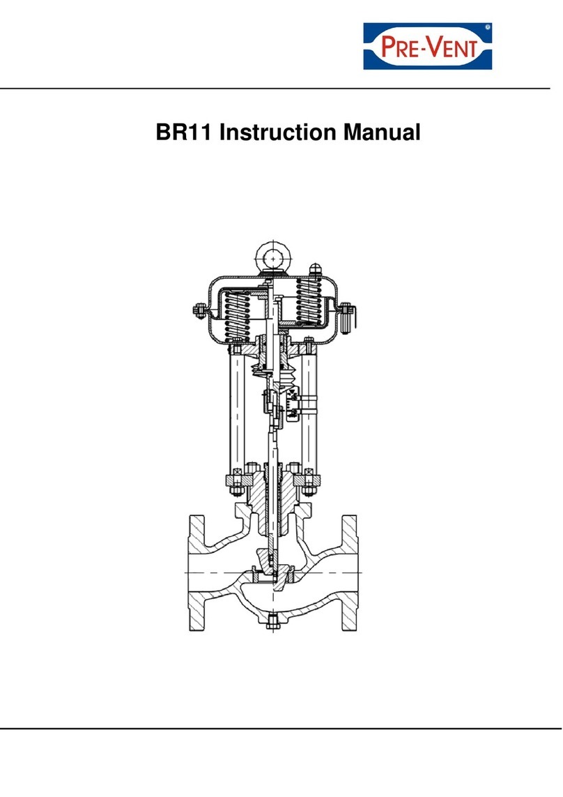
Designation and part name
Number on
the
drawing
Part name Number on the drawing Part name
1 Valve body 33 Guide sleeve
2 Valve seat 34 O-ring
3 Seat gasket 35 O-ring
4 Plug 36 Connecting plate
4A Plug 37 Screw
5 Guide sleeve 38 Spring
5B Guide sleeve 39 Gasket
6 Gasket 40 Bottom diaphragm case
6A Gasket 41 Nut
6B Gasket 42 Diaphragm
6B2 Gasket 43 Diaphragm plate
7 Bonnet 44 Lug
7A Bonnet 45 Screw
8 Pin 46 Nut
8A Pin 47 Flat washer
9 Nut 48 Limit sleeve
10 Screw 49 Upper diaphragm case
11 Stem 50 Exhaust plug
11A Stem 51 Exhaust cover
12 Nut 52 Seal plate
13 Elastic washer 52B Seal plate
14 Flat washer 53 Bellows
15 Packing 53B Bellows
16 Press plate 54 Bellows connecting plate
17 O-Ring 54B Bellows connecting plate
18 Gasket for upper packing 55 Bracket
19 Screw plug 55B Bracket
20 Screw cap 56 Bellows seal plate
21 Pillars 56B Bellows seal plate
22 Stroke plate 57 Bellows guide plate
23 Nut 57B Bellows guide plate
24 Screw 58 Pin
25 Column clamping ring 59 Bottom stem
26 Clamping plate 60 Bottom bonnet
27 Nut 61 Screw
28 Screw 62 Nut
29 Connecting nut 63 Upper bonnet
30 Nut 64 Upper stem
31 Dustproof case 65 O-ring
32 Actuator stem

17
Manual Version 1.1 07.11.2019
Fig. 1 Control valve with standard bonnet and pneumatic actuator

18
Manual Version 1.1 07.11.2019
Fig. 2. Control valve DN 15...50 with bellows seal

19
Manual Version 1.1 07.11.2019
Fig. 3. Control valve DN 65...200 with bellows seal

20
Manual Version 1.1 07.11.2019
PRE-VENT GmbH
Sales - Production - Service
Piracher Straße 74
84489 Burghausen, Germany
fon +49 8677 98788-0
fax +49 8677 98788-80
Email:
Web: www.pre-vent.com
Manual version 1.1 07.11.2019
10.CONTACTING US
Details / specific information (Operating instructions with spare parts lists) are available for download
on our website.
Table of contents
Other preVent Control Unit manuals