Delta Controls DRP-T0B User manual

I
NSTALLATION
G
UIDE
DRP-T0B Rev 8.6 Installation Guide
Document Edition 1.3
Document Edition 1.3
Product Description
The DRP-T0B is used to interface to systems that do not
utilize a front-end system to display and configure information
and objects. This controller can be used to vie object and
system status, edit and configure objects that are setup in a
menu structure. Different menu structures can be created
relative to pass ord privileges as ell as system options such
as Set Time and Date or Reset.
This controller only communicates on LINKnet and has no I/O
other than the onboard temperature sensor. Programming for
equipment is done through GCL+ and programming for the
DRP-T0B is done ith MN (Menu) objects. This is done
through the System controller that the DRP-T0B is connected
to.
Important Information
The DRP-T0B is only supported on System level controllers ith 16 Mb of flash memory.
The DRP-T0B ill only ork ith firm are version 3.33 Release 2 and higher.
ORCAvie OWS and controller firm are must all be of the same version number (i.e. 3.33) to
be compatible. When upgrading any of these products from older versions (i.e. 3.22 or 3.30),
you must upgrade all the remaining products.
Packa e Contents
Product: DRP-T0B (Rev 8.6)
DRP-T0B (Rev 8.6) Installation Guide
T o pin connector (AMP643817-2) 18 gauge (orange color)
T o pin connector (AMP643820-2) 24 gauge ( hite color) for RS-485 connection
2 #6 x 1” scre s
1 Service Tool cable
Related Documents
Delta Controls Wiring Guidelines
ORCAvie Operator Guide
ORCAvie Technical Reference Manual

Delta Controls
Pa e 2 of 12
Release Notes for related Firm are
Required Tools
AMP Tool (Part Number DTT970)
Wire Cutter
Phillips scre driver
Cautions or Warnin s
This controller is an Electro-statically sensitive device. Proper ESD protection (ground strap)
should be used hen installing this product so that damage to the product does not occur.
Equipment damage or loss of data may occur if these procedures are not follo ed as specified.
Installations requirin CE conformance: All iring for CE rated products must use an extra lo
voltage (SELV) or protective extra lo voltage (PELV) transformer. Use safety-isolating
transformers, (Class II transformer) per EN61558. The transformer must be rated for 100% duty
cycle.

Document Edition 1.3
Pa e 3 of 12
Mountin
The DRP-T0B is housed in a plastic enclosure ith a removable back piece. It can be mounted on a standard
North American 1110 electrical box as ell as some standard international electrical boxes. This controller also
comes equipped ith a snap on back plate that can be used for quick mounting to any surface or used for
handheld operation.
To remove the base from the controller, back off the t o back plate scre s as sho n. These should only be
backed off enough to separate the base from the Room Controller they should not be removed.
The base can then be separated from the controller. Open the controller slightly as sho n until you feel the
hinges on the left side release.

Delta Controls
Pa e 4 of 12
The back piece can be mounted to an appropriate electrical box, cabinet or all. The diagram belo sho s the
base ith the iring opening and mounting holes above, belo and on either side of the opening There are also
mounting holes on each corner of the back plate. The mounting holes above and belo the iring opening align
ith a standard electrical box. The four mounting holes at each edge of the back plate or the 2 holes on each
side of the opening can be used for mounting directly onto a all if an electrical box is not used (it is
recommended that plastic scre anchors – size 10-12 1” - be used. Larger steel all anchors may be visible
under the back plate mounting pads).
If the controller is being mounted ith the back plate there are t o holes on either side of the back plate at the
top. The back plate also has one large hole designed for hanging the controller.
To reattach the base, insert the hinged side first and then fold the t o sections together. Tighten the scre s to
fasten the base to the controller.
Do not over tighten the scre s on the controller. This may lead to damage to the housing or
scre holes.

Document Edition 1.3
Pa e 5 of 12
Board Layout

Delta Controls
Pa e 6 of 12
Wirin General
All iring must conform to NEC and local codes and regulations. Use earth ground isolating step-do n Class 2
transformers. Do not use autotransformers. Determine supply transformer rating by summing total VA of product
and output loads.
Risk of Electric Shock or Fire
More than one disconnect s itch may be required to de-energize the
equipment before servicing.
Input Class 2 Po er Supplies are interconnected. Use only Class 2
sources suitable for interconnections.
All terminals are acceptable for Class 2 Circuit connections only
Use copper conductors only
Power
This product is designed to use a 24VAC or 24VDC Class 2 po er supply. The controller can be po ered from
a transformer or from the Service Tool Port of the System Controller if the supplied cable is used. A single
transformer may be used to po er multiple controllers and/or auxiliary field devices (actuators, etc.) provided
the follo ing conditions are met:
All devices MUST be ½ ave rectified. Mixing po er bet een ½ ave and full ave rectified devices
ill damage both the transformer and connected equipment.
The transformer is properly sized, including line losses for the total VA requirements.
Polarity is observed bet een controllers ( ith respect to 24~ and Gnd).
The transformer secondary is fused for its maximum rated load (4A max for Class 2 circuits).
When po er is applied to the controller, all of the LCD segments ill appear on the
display for a fe seconds.

Document Edition 1.3
Pa e 7 of 12
Network Communication
The controller communicates on Delta Controls LINKnet net ork through the Service Tool Port or an RS-485
connection.
MS/TP (RS485) Wirin
For detailed information on LINKnet iring refer to Delta Controls Wiring Guidelines.
The proper specified cabling must be used to ensure reliable communications. (22-24 AWG
t isted pair, 100-120 ohms impedance, 17 pF/ft or lo er capacitance, ith a braided or aluminum
foil shield.)
Controllers should al ays be ired together in a daisy-chain fashion. Attempting to connect them
using a starred or bus configuration ill cause problems on the net ork.
Net orks ith a total length greater than 4000 ft or ith more than 50 controllers require a
repeater (RPT-768).
LINKnet net orks that have only 1-2 controllers, and have less then 100 ft of cable length do not
require net ork terminators.
When using this product special consideration must taken into ho the product is installed. The follo ing are
guidelines on ho to apply this product.
The DRP-T0B must be connected to a DSC controller. The DAC controllers do not have enough
memory to support the functionality required.
The DRP-T0B communicates only on LINKnet.
The Service Tool Port on all controllers (except the DLC) is internally connected to NET1. This
means that if you ant to connect the controller to NET2 the supplied Service Tool Cable cannot
be used. The controller must be hard ired ith the connections in the back on the controller.
If using an Ethernet DSC the DRP-T0B can be connected to the DSC ith the supplied Service
Tool Cable.
If using a non Ethernet DSC that is net orked, the DRP-T0B must be connected using the
connections on the back of the controller.
The follo ing diagram sho s the net ork configuration hen using an Ethernet DSC.

Delta Controls
Pa e 8 of 12
The follo ing diagram sho s the net ork configuration hen using a non Ethernet DSC.

Document Edition 1.3
Pa e 9 of 12
Usin the AMP Tool
1. Insert the AMP connector into the cartridge of the AMP tool as sho n. The AMP connector and tool
cartridge are keyed so that it can only be inserted one ay, ith the ire connections pointing to ard
the handle of the tool.
2. Line up the first ire terminal on the connector ith the round notch on the AMP Tool.
3. Insert the ire into the slot so that it seats against the bottom edge of the cartridge. Squeeze and
release the trigger of the AMP tool. The AMP connector ill automatically advance to the next ire slot.
Repeat the procedure until all the ires have been terminated into the AMP connector.
4. When all the ires have been inserted and crimped to the connector, the connector can be removed
easily by sliding the connector out of the AMP Tool cartridge.

Delta Controls
Pa e 10 of 12
Indicators
LED Function Description
Scan CPU Scan Indicator This red LED flashes at a rate relative to the CPU scan rate.
Net ork
(NET1)
MS/TP (RS485)
Communication
Status Indicators
The green LED flashes to indicate hen the controller is
transmitting out the port, and the red LED flashes to indicate hen
the controller is receiving data through the port. If communication
is good, both LEDs ill flash at a high rate.
Product Specifications
Power Requirements 24 VAC 50/60Hz or 10-35 VDC Class 2
Power Consumption 5 VA
Ambient Ratin s 32° to 120°F (0° to 50°C), 10 to 90% RH (non condensing)
Communication Ports
NET1 LINKnet
Communication: 76800 bps
Service
Port RJ-11 Jack
Inputs 1 Internal Input configured for the follo ing input type:
10 KΩ Thermistor
Technolo y 32 bit processor
1 MB (8 megabit) Flash Memory
256 KB SRAM memory
Listin s UL 916 Listed
BTL Listed ( ith V3.30 firm are only)
Compliance CE
FCC

Document Edition 1.3
Pa e 11 of 12
CE - DECLARATION OF CONFORMITY
According to ISO/IEC Guide 22 and EN 45014
Manufacturer's Name: Delta Controls
Manufacturer's Address: 17850 56
th
Avenue
Surrey, British Columbia
Canada
V3S 1C7
Declares that the product (s):
Product Name: Room Controller
Model Numbers: DRP-T0B
Product Options: All
Conforms to the follo ing Product Specifications:
EN 55022:1994 Limits and Methods: ITE Disturbances
EN 55022:1994 Radiated and Conducted Emissions Class B
EN 50082-1:1997 Generic Immunity: Residential
EN 61000-4-3:1996 RF EMF Immunity Level A
ENV 50204:1995 RF EMF Immunity (Keyed Carrier) Level A
EN 61000-4-6:1996 Conducted Immunity Level A
EN 61000-4-4:1995 EFT/Burst Immunity Level B
EN 61000-4-2:1995 +A1:1999 ESD Immunity Level B
EN 61000-4-5:1995 Surge Immunity Level B
EN 61000-4-11:1994 Voltage Dips / Interruptions Level B/C/C
Supplementary Information
The product(s) here ith comply ith the requirements of the EMC Directive 89/336/EEC. The
product(s) ere tested in a typical configuration.
Lee Dickson
Quality Assurance Manager

Delta Controls
Pa e 12 of 12
FCC Compliance Information
This equipment has been tested and found to comply ith the limits for a Class B digital device, pursuant to part
15 of the FCC Rules. These limits are designed to provide reasonable protection against harmful interference
hen the equipment is operated in a commercial environment. This equipment generates, uses, and can radiate
radio frequency energy and, if not installed and used in accordance ith the instruction manual, may cause
harmful interference to radio communications. Operation of this equipment in a residential area is likely to cause
harmful interference in hich case the user ill be required to correct the interference at his o n expense.
Industry Canada Compliance Statement
ICES-003 This Class B digital apparatus meets all requirements of the Canadian Interference-Causing
Equipment Regulations
Cet appareil numérique de la Classe B Respecte toutes les exigences du Règlement sur le matérial
brouiller du Canada.
This product conforms to the follo ing UL requirements:
UL916: Energy Management Equipment
Table of contents
Other Delta Controls Controllers manuals
Delta Controls
Delta Controls DLC-G1212 User guide
Delta Controls
Delta Controls eZV-440 User guide
Delta Controls
Delta Controls DSC-1280 User manual
Delta Controls
Delta Controls eZFC-424R4-24 User guide
Delta Controls
Delta Controls Red5-PLUS/EDGE-11 Series User manual
Delta Controls
Delta Controls Red5-PLUS/EDGE-6 Series User manual
Delta Controls
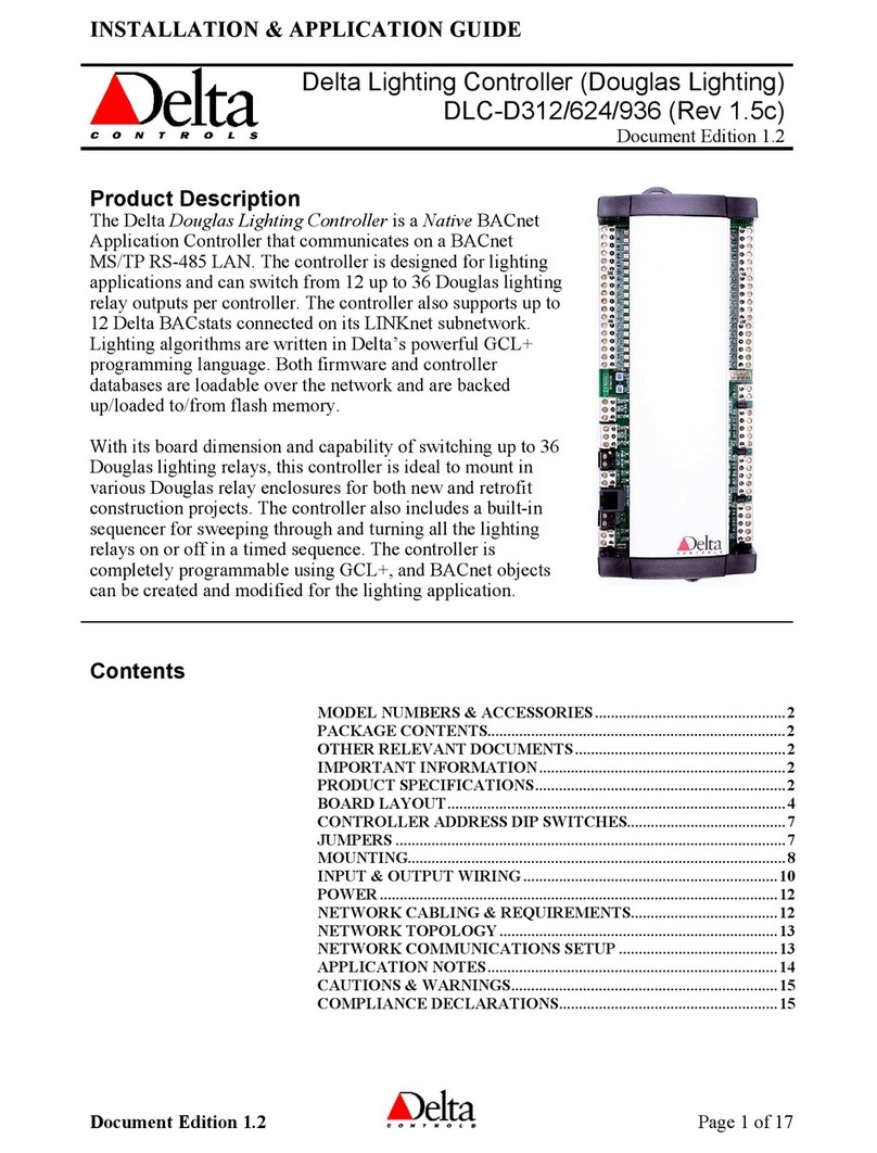
Delta Controls DLC-D312 User guide

