DigiSpec DTT-PRO Installation manual

DTTDTT
DTTDTT
DTT-Pr-Pr
-Pr-Pr
-Proo
oo
o
Digital Date / Time Titler
Operation Manual
May 2011
TM

2
DTTDTT
DTTDTT
DTT-Pr-Pr
-Pr-Pr
-Proo
oo
o
TO PREVENT ELECTRIC SHOCK, DO NOT REMOVE THE
COVER. DO NOT EXPOSE THE EQUIPMENT TO RAIN OR
MOISTURE. NO USER SERVICEABLE PARTS ARE INSIDE.
REFER SERVICING TO QUALIFIED PERSONNEL.
CAUTION!
RISK OF ELECTRICAL SHOCK!
DO NOT OPEN!
WARNING!
THISEQUIPMENTGENERATES,USES,ANDCANRADIATERADIOFRE-
QUENCY ENERGY AND IF NOT INSTALLED AND USED IN ACCOR-
DANCE WITH THE INSTRUCTION MANUAL MAY CAUSE INTERFER-
ENCE TO RADIO COMMUNICATIONS. IT HAS BEEN TESTED AND
FOUND TO COMPLY WITH THE LIMITS FOR A CLASS A COMPUTING
DEVICE PURSUANT TO SUBPART J OF PART 15 OF FCC RULES,
WHICH ARE DESIGNED TO PROVIDE REASONABLE PROTECTION
AGAINST SUCH INTERFERENCE WHEN OPERATED IN A COMMER-
CIAL ENVIROMENT. OPERATION OF THIS EQUIPMENT IN A RESI-
DENTIALAREA IS LIKELY TO CAUSE INTERFERENCE IN WHICH CASE
THE USER AT HIS/HER OWN EXPENSE WILL BE REQUIRED TO TAKE
WHATEVER MEASURES MAY BE REQUIRED TO CORRECT THE IN-
TERFERENCE.

3
CONTENTS
Introduction..................................................................................................................................................4
Features&Specifications.......................................................................................................................4
Features...........................................................................................................................................4
Specifications................................................................................................................................4
Connections...................................................................................................................................5
FrontPanel.....................................................................................................................................5
RearConnector.............................................................................................................................5
OperatingMode.............................................................................................................................6
ProgrammingMode......................................................................................................................6
TITLERSETUP...............................................................................................................................6
TIME-DATE......................................................................................................................................7
T-D SETTING.......................................................................................................................7
TIMEFORMAT.....................................................................................................................8
DATEFORMAT..................................................................................................................8
DST........................................................................................................................................8
EXIT.......................................................................................................................................9
DISPLAY...........................................................................................................................................9
TITLER...............................................................................................................................10
TIME-DATE........................................................................................................................10
VIDEOLOSS.....................................................................................................................10
VLOUTPUT...........................................................................................................11
TIME-DATE............................................................................................................11
CAPTURE.............................................................................................................12
VLMESSAGE.......................................................................................................12
EXIT.........................................................................................................................12
GRAYSCALE....................................................................................................................13
BORDER...........................................................................................................................13
EXIT.....................................................................................................................................14
VideoLossDetection............................................................................................................................14
MasterReset............................................................................................................................................14
Warranty....................................................................................................................................................15
FIGURES
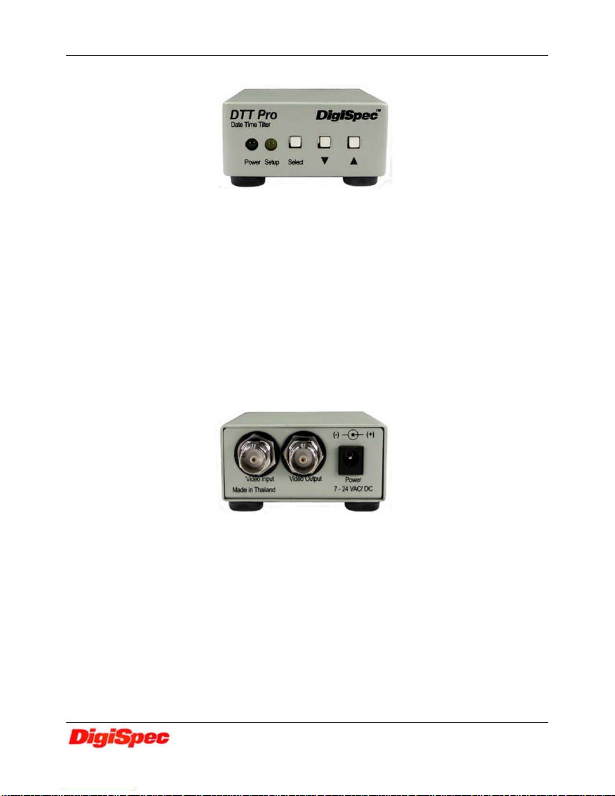
Figure 1: DTT-Pro Front Indicator LEDs and Programming Push buttons...............................5
Figure2:DTT-Pro Rear Connections..................................................................................................5

4
SPECIFICATION
Video VideoInput /Output BNC - 1 VP-P Input +/- 20%, 1V P-POutput 75 Ohm Term. or UnTerm.
VideoFormat NTSC/EIAorPAL/CCIR
DisplayTitler Format 20Alpha-NumericCharacterOn/OffSelectable
Date-TimeFormat On/OffSelectable
MMM-DD-YY HH:MM:SSA(A-AM, P-PM) 12Hr
MMM-DD-YYHH:MM:SS 24Hr
DD-MMM-YY HH:MM:SSA(A-AM, P-PM) 12Hr
DD-MMM-YYHH:MM:SS 24Hr
YY-MMM-DD HH:MM:SSA(A-AM, P-PM) 12Hr
YY-MMM-DDHH:MM:SS 24Hr
Clock Accuracy +/- 5 ppm
On-ScreenWidth 75% of activedisplay width
CharacterHeight 12 lines (5.8% of total image height)
Control / Programming
ControlInterface 3 Front Panel Buttons: Select, Up, and Down
StatusIndicators 2 Front PanelLEDs:Power(Greeen), Setup (Yellow)
Earth Grounding ScrewTerminal onBottom ofUnit
Back-UpBattery InternalRechargeableNiMH battery
Warranty 2 Years Parts and Labor
Size / Weight / Power
Size 3 3/8” D x 2 5/8” W x 1 1/8” H
85mm D x 62mm W x 30mm H
Weight 9 oz / .28 Kg
Power Multi Voltage Input 7.5-24 V DC @ 65mAor 24VAC @ 100 mA
2.1mmx 5.5mmDCPower Connector-Center Positive
INTRODUCTION
TheDTT-Pro single-channel Date-Time-Titleroverlaysdate, time andcameraidentificationonto a videoimage,
identifying precisely when and where an event has taken place. The output signal may be displayed on a monitor,
recordedon aVCR/DVR, orprintedon avideo printer.Thecharacters havefull programmability in8 grayscales along
withbackground in 8grayscales. In theeventthe video inputfailsor not usedtheDTT-Prowill outputacomposite video
imagewith theT/D Titleinformationvisible.Full 7.5-24VDCorAC Operation.Power input fullprotected from surgeand
lightningwith screwterminal earthground.
The DTT-Pro uses a precision crystal-controlled clock for unparalleled +/-5 ppm accuracy. Compatible with
both color and monochrome cameras NTSC/EIAor PAL/CCIR formats, its compact size and low power consumption
makeit perfect forportableand covertapplications.Fully programmable forallUS andEuropeanTime/Date formats for
worldcompliance.
FEATURES
Displays Hours, Minutes and Seconds
Titles up to 20 Characters
CharacterBorder Selectable8grayscale
CharacterColor Selectable8 grayscale
Video Signal Loss Detection
CompositeVideo Outputwithout VideoInput
PowerFailureIndicator
LowVoltage, LowPowerAC/DC
NTSC / PALJumper Selectable
Workswith Coloror Monochrome Cameras
Informationcan be PositionedAnywhereOn-Screen
FEATURES & SPECIFICATIONS
DTT-Pro (DATE/TIME TITLER)
5
TheDTT-Prooperatesfrom amultivoltageinput 7.5V to 24VDC 65mAor24VAC100mA.Thepower
input connector is a standard 2.1mm x 5.5mm DC Coax power jack, must have positive (+) on the
centerandnegative (- orground)ontheouter shell. Theunitisreverseprotected for correctpolarityand
is indicated by the Green Power LED being lit on the front panel.
Rear Connectors
Front Panel
CONNECTIONS
Video
Input/Output Thevideo input andoutput are locatedon the rearofthe unit.(seeFigure 2).Thevideo input connects
tothevideosource via the leftBNC connector.Thevideooutputconnects to adisplay,recording device,
switcher,orother equipment via therightBNCconnector. Boththeinputand outputare1V P-Pinto75
ohmsunbalancedEIAstandardRS-170A/NTSCorCIR/PALvideoformat. Improperinputtermination
orlooping will causethe video leveltobe toolowand effect thetext insertion. Thevideooutput is1VP-
Pwhether terminated with75 ohm ornot and candrivetwo 75ohmterminated loadswithoutdegrada-
tion.Additionaloutput load willcause thelevelto decreaseproportionally.
Power Input
Power Green Signifies power is supplied to the unit
Setup Yellow This Yellow LED willlight whenever goingtothe Programmingmode
Programming push buttons
Select button Press this button to go to programming mode
Downbutton In the Operatingmodepress thisbuttonto movedownthe Titleand Date-Time overlayon the screen.
In the Programming mode press this button to move down the cursor or change some setting.
Upbutton In the Operatingmode press thisbutton tomoveup theTitle and Date-Timeoverlay onthescreen.
In the Programming mode press this button to move up the cursor or change some setting.
LED Indicators
Figure 1: DTT-Pro Front Indicator LEDs and Programming Push buttons
Figure 2: DTT-Pro Rear Connections
DTT-Pro (DATE/TIME TITLER)
6
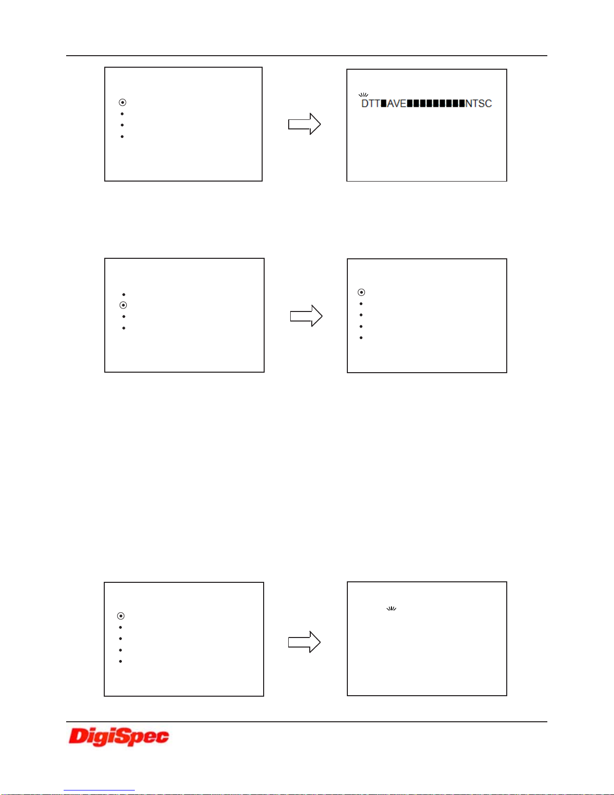
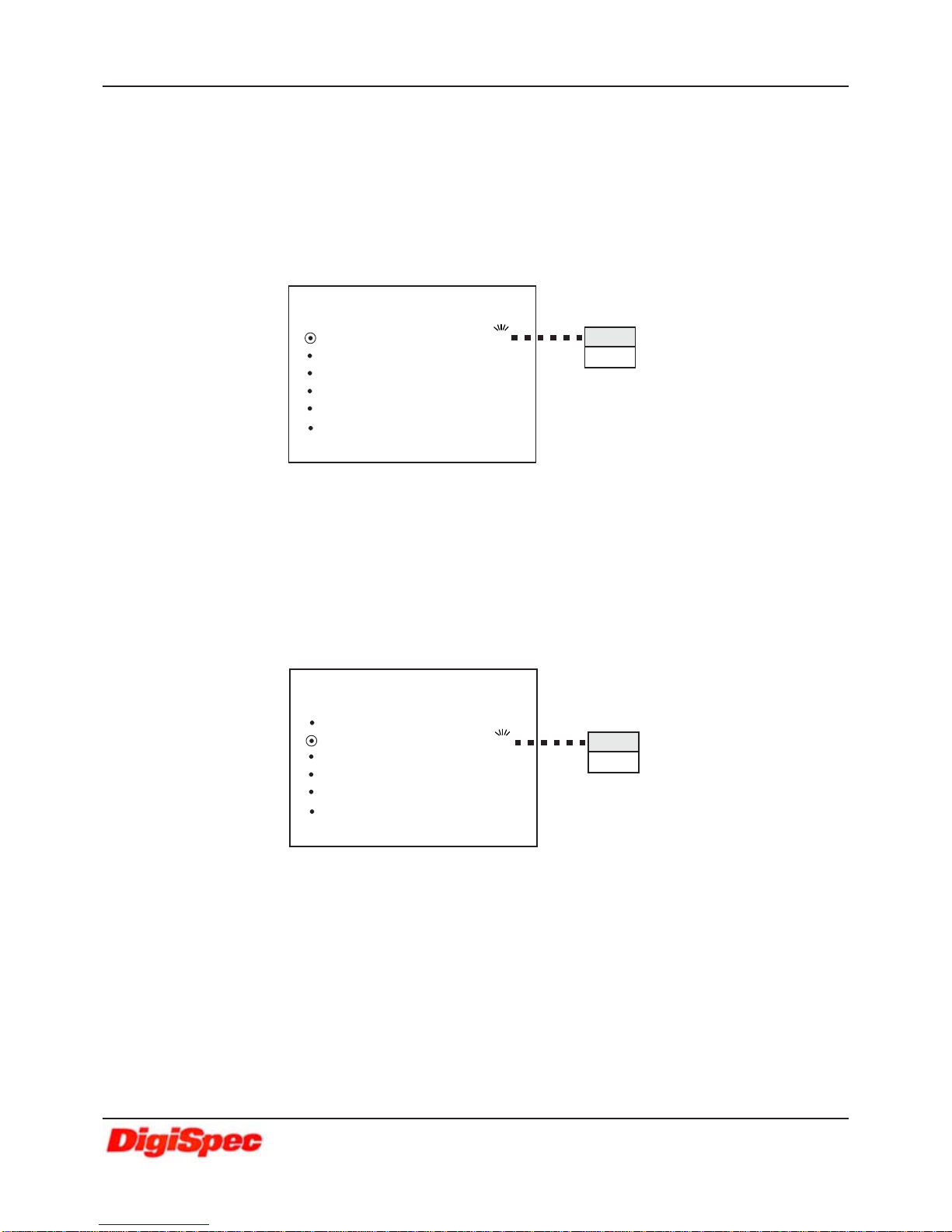
PROGRAMMING
TITLER SETUP
Move the cursor by pressing the “UP” or “Down” button to the “TITLER SETUP” and press the“Select” button . The
“TITLERSETUP” menu willapprearandthefirst character willflashandaspace character isdisplayedasablock. Press
the“Up”or “Down”button toscrollthroughthe available characters.Whenthedesired character isdisplayedselectit by
press the “Select” button. This will set the selected character and move the cursor to the next character to the right.
Pressthe “Select”buttonand the cursorwillsequence throughall20positions andthenexitthe “TITLE SETUP”and go
back to the “MAIN MENU” by pressing the “Select” button from the end of the sequence.
PROGRAMMING MODE
TheDTT-Pro is programmedbypressingthe“Select”buttonwhileinoperating mode thenthe“MAIN MENU”will appear
and the Setup indicator (Yellow LED) will light. Press the “UP” or “Down” buttons to move the cursor up or down and
press the “Select” button to select the current line item.
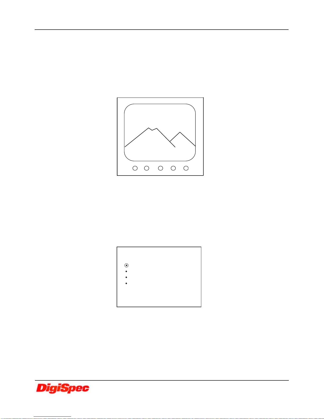
OPERATING MODE
TheDTT-Prosingle-channelDate-Time-Titleroverlaysdate,time and titleontoavideoimage,identifying precisely when
and where an event has taken place. The output signal may be displayed on a monitor, recorded on a VCR, DVR or
printedona video printer.
Press “UP” or“Down” buttonto moveup or downthe Titleand Date-Time displaythat overlayson thescreen.
Press “Select”button forgoing totheProgramming mode
NOTE : Title and Date-Time can setting ON or OFF .Please refer to page 10.
DTT AVE NTSC
JAN-01-08 8:00:00A
MAINMENU
TITLER SETUP
TIME - DATE
DISPLAY
EXIT
DTT-Pro (DATE/TIME TITLER)
7
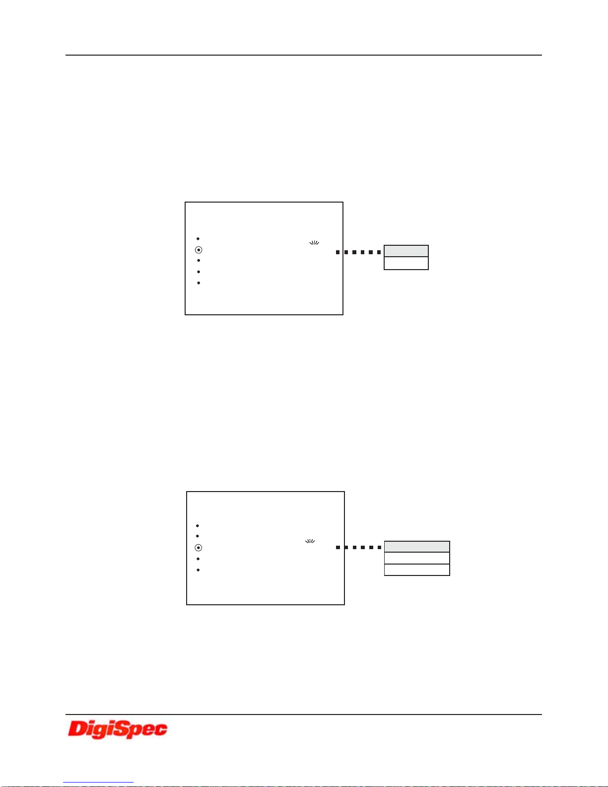
PROGRAMMING
TIME-DATE
Move the cursor by pressing the “Up” or “Down” button to the “TIME-DATE” selection and press the “Select” button.
The“TIME-DATE”menuwillapprear.
TME-DATE SETTING
Movethe cursorbypressing the “Up”or “Down”buttons to access the“TIME-DATE”selectionand pressthe
“Select” button . The “TIME-DATE” menu will apprear and the month will flash. Press the “Up” or “Down” to
scroll through the available date and time formats. Press the “Select” button to select and move the cursor
followingthesequence below.
There are 6 prompts associated with this set-up screen and they sequence in the order displayed:
MMM : Month displayed as (JAN, FEB, MAR,...... NOV, DEC)
DD : Date(1-31)
YY : Year (00-99). Note: the year 2000 is 00
HH : Hours(1-12 withAM/PM, or00-23, dependingon 12 or 24 time format)
MM : Minutes(00-59)
SS : Seconds(00-59)
T-D SETTING
TIME FORMAT 12 Hour
DATE FORMAT MMM-DD-YY
DST OFF
EXIT
TIIME-DATE T-DSETTING
JAN-01-08 8:00:00 A
TITLER SETUP
TIME - DATE
DISPLAY
EXIT
MAINMENU T-D SETTING
TIME FORMAT 12 Hour
DATE FORMAT MMM-DD-YY
DST OFF
EXIT
TIIME-DATE
TITLER SETUP
MAINMENU
TITLER SETUP
TIME - DATE
DISPLAY
EXIT
DTT-Pro (DATE/TIME TITLER)
8
DST (DAYLIGHT SAVING TIME)
Movethe cursor bypressingthe“Up”or“Down”buttons to accessthe“DST”selectionandpress the “Select”
button. The “DST” will flash. Change this by pressing the “Up” or “Down” buttons and press the “Select”
button to select “USA” , “CANADA” , “AUSTRALIA” , “TASMANIA” or ”OFF” DST. This mode automatically
adjusts for daylight saving time, a 1-hour decrease in the Fall and a 1-hour increase in the Spring for the
selectedcountries orterrritories.
PROGRAMMING
DATE FORMAT
Move the cursor by pressing the “Up” or “Down” buttons to access the “DATE FORMAT” and press the
“Select”button.Then the dateformatwillflash. Change thisbypressingthe “Up” or“Down” buttons andpress
the “Select” button to select “MMM-DD-YY” , “YY-MMM-DD” or ”DD-MMM-YY” date format. This setting will
effect date display in the operating display and the video loss display.
MMM-DD-YY Thedate willdisplay inthe MMM-DD-YYformat inthe operatingscreen andthe video loss
display.
YY-MMM-DD The date will display in theYY-MMM-DD format in the operating display and the video loss
display.
DD-MMM-YY The date will display in the DD-MMM-YY format in the operating display and the video loss
display.
TIME FORMAT
Movethecursor by pressingthe“Up”or “Down”buttontoaccess the “TIME FORMAT”and press the “Select”
button.The timeformat will flash.Change this selectionby pressingthe“Up” or“Down” buttonandpress the
“Select” button to select “12 Hour” or ”24 Hour” time format .
12 Hour Displays Time in the 12 Hour format in the operating screen and video loss display
warningscreen
24 Hour DisplaysTime inthe 24Hour format in operating screenand videoloss display
warningscreen.
T-D SETTING
TIME FORMAT 12 Hour
DATE FORMAT MMM-DD-YY
DST OFF
EXIT
TIIME-DATE
12Hour
24Hour
T-D SETTING
TIME FORMAT 12 Hour
DATE FORMAT MMM-DD-YY
DST OFF
EXIT
TIIME-DATE
MMM-DD-YY
YY-MMM-DD
DD-MMM-YY
DTT-Pro (DATE/TIME TITLER)

9
PROGRAMMING
EXIT
Move the cursor by pressing the “Up” or “Down” buttons to access the “EXIT” and press the
“Select” button to go back to the “MAIN MENU”
OFF Turnoff the daylightsavingtime function
USA Second Sunday of March after 2:00 a.m. (+1 hr)
FirstSunday ofNovemberafter 2:00 a.m. (-1 hr)
Canada Second Sunday of March after 2:00 a.m. (+1 hr)
FirstSunday ofNovemberafter 2:00 a.m. (-1 hr)
Australia Last Sunday of October after 2:00 a.m. (+1 hr)
Last Sunday of March after 3:00 a.m. (-1 hr)
Tasmania Last Sunday of October after 2:00 a.m. (+1 hr)
Last Sunday of March after 3:00 a.m. (-1 hr)
DISPLAY
Movethe cursorbypressing the“Up” or“Down”buttons toaccessthe “DISPLAY”menuand pressthe“Select”button.
The“DISPLAY” menu willapprear.
TITLER SETUP
TIME - DATE
DISPLAY
EXIT
MAINMENU TITLER ON
TIME-DATE ON
VIDEO LOSS
GRAYSCALE
BORDER
EXIT
DISPLAY
T-D SETTING
TIME FORMAT 12 Hour
DATE FORMAT MMM-DD-YY
DST OFF
EXIT
TIIME-DATE
TITLER SETUP
TIME - DATE
DISPLAY
EXIT
MAINMENU
T-D SETTING
TIME FORMAT 12 Hour
DATE FORMAT MMM-DD-YY
DST OFF
EXIT
TIIME-DATE
OFF
USA
CANADA
AUSTRALIA
TASMANIA
DTT-Pro (DATE/TIME TITLER)
10
PROGRAMMING
TIME-DATE
Movethe cursor by pressingthe“Up” or“Down”button to“TIME-DATE”andpress the “Select”button.Then
the time-date will flash .Change by pressing the “Up” or “Down” button and press “Select” button for select
“ON”or ”OFF”titlerdisplay on theoperating screen.
ON : Turn on time and date display on the screen in operating mode
OFF : Turn off time and date display on the screen in operating mode
TITLER
Move the cursor by pressing the “Up” or “Down” buttons to access the “TITLER” and press “Select” button.
Then the titler will flash. Change by pressing the “Up” or “Down” buttons and then press “Select” button to
select “ON” or ”OFF” titler display on the operating screen.
ON : Turn on the titler display on the screen in the operating mode
OFF : Turn off the titler display on the screen in the operating mode
TITLER ON
TIME-DATE ON
VIDEO LOSS
GRAYSCALE
BORDER
EXIT
DISPLAY ON
OFF
VIDEO LOSS
Move the cursor by pressing the “Up” or “Down” buttons to access the “VIDEO LOSS” menu and press the
“Select”button.The “VIDEO LOSS”menuwill apprear.
TITLER ON
TIME-DATE ON
VIDEO LOSS
GRAYSCALE
BORDER
EXIT
DISPLAY
ON
OFF
DTT-Pro (DATE/TIME TITLER)

11
VL OUTPUT (Video Loss Output)
Movethe cursorby pressing the“Up”or “Down”button to “VL OUTPUT”andpress “Select”button . Thenthe
videoloss output willflash.Change by press“Up”or “Down”buttonand press “Select”buttonfor select“RED”
,“BLUE” or ”VIDEO”.
RED :Video losswarningwith redbackground color whenvideo loss
BLUE :Video losswarningwith bluebackground color whenvideo loss
VIDEO :Theinputvideois passedthroughtheDTT-Pro continuouslywhetherthereisa videolosscondition or
normalcondition.Thiswill allowdevicesin linewiththe DTT-Pro tocontinue to recordor to maketheir
own decision if video is lost or not.
TIME-DATE
Movethe cursorby pressing the“Up”or “Down” button to“TIME-DATE”and press “Select” button.Thenthe
Time-Datewill flash .Changebypressing the“Up”or “Down”buttonandpress “Select”buttonforselect “ON”
or”OFF”the Time-Datedisplay on thevideo loss screen.
ON : Turn on time and date display on the screen in video loss mode
OFF : Turn off time and date display on the screen in video loss mode
PROGRAMMING
TITLER ON
TIME-DATE ON
VIDEO LOSS
GRAYSCALE
BORDER
EXIT
DISPLAY
VL OUTPUT RED
TIME-DATE ON
CAPTURE ON
TITLER ON
VL MESSAGE ON
EXIT
VIDEOLOSS
RED
BLUE
VIDEO
VL OUTPUT RED
TIME-DATE ON
CAPTURE ON
TITLER ON
VL MESSAGE ON
EXIT
VIDEOLOSS
VL OUTPUT RED
TIME-DATE ON
CAPTURE ON
TITLER ON
VL MESSAGE ON
EXIT
VIDEOLOSS
ON
OFF
DTT-Pro (DATE/TIME TITLER)

12
PROGRAMMING
Movethe cursor by pressingthe“Up” or“Down”button to “TITLER”andpress “Select”button.Thenthe titler
will flash. Change by pressing the “Up” or “Down” button and press “Select” button for select “ON” or ”OFF”
titler display on the Video Loss Screen .
ON : Turn on the titler display on the screen in the video loss mode
OFF : Turn off the titler display on the screen in the video loss mode
Movethe cursor by pressingthe “Up”or “Down”button to“VL MESSAGE” andpress “Select”button. Then
theVL message willflash.Change by pressingthe“Up”or “Down” button andpress“Select” buttonforselect
“ON” or ”OFF” the Video Loss message display on the video loss screen .
ON : Turn on the “VIDEO LOSS” message that display on screen in the video loss mode
OFF : Turn off the “VIDEO LOSS” message that display on screen in the video loss mode
Move the cursor by pressing the “Up” or “Down” button to “CAPTURE” and press “Select” button. Then the
capturewillflash. Change bypressingthe “Up”or“Down” buttonandpress“Select”button for selectdateand
time frozen “ON” or ”OFF” in the Video Loss Screen .
ON : Date and time that show in video loss screen will frozen at the time that video loss occur.
OFF : Date and time that show in video loss screen will not frozen.
VL MESSAGE
TITLER
CAPTURE
VL OUTPUT RED
TIME-DATE ON
CAPTURE ON
TITLER ON
VL MESSAGE ON
EXIT
VIDEOLOSS
ON
OFF
VL OUTPUT RED
TIME-DATE ON
CAPTURE ON
TITLER ON
VL MESSAGE ON
EXIT
VIDEOLOSS
ON
OFF
VL OUTPUT RED
TIME-DATE ON
CAPTURE ON
TITLER ON
VL MESSAGE ON
EXIT
VIDEOLOSS
ON
OFF
DTT-Pro (DATE/TIME TITLER)

13
PROGRAMMING
Movethe cursor by pressingthe “Up” or“Down” button to“GRAYSCALE” and press “Select”button.Then
the“GRAYSCALE”menuwillappear. Press“Up”or“Down” buttontochangethe character colorin8levels of
grayscalecolor andpress“Select”button forselectingdesiredgray scale. Settingthiswill effect thecharacter
colorin theOperating Display Mode.
Movethe cursor bypressing the “Up” or “Down” button to“BORDER” andpress “Select”button .Then the
“BORDER” menu will appear.Press“Up”or“Down” button tochangethe character bordercolorin 8levelsof
gray scale color and press “Select” button for selecting the desired gray scale border color. Setting this will
effectwith character bordercolor in OperatingDisplay Mode.
Movethe cursorbypressing the “Up”or“Down” buttons toaccess the“EXIT”and pressthe “Select” button
to go back to the “DISPLAY” menu
EXIT
GRAYSCALE
BORDER
VL OUTPUT RED
TIME-DATE ON
CAPTURE ON
TITLER ON
VL MESSAGE ON
EXIT
VIDEOLOSS
TITLER ON
TIME-DATE ON
VIDEO LOSS
GRAYSCALE
BORDER
EXIT
DISPLAY
TITLER ON
TIME-DATE ON
VL OUTPUT RED
GRAYSCALE
BORDER
EXIT
DISPLAY
Color of character will
change following gray
scale select.
AAAAAAAAAAAAAAAAAAAA
AAAAAAAAAAAAAAAAAAAA
AAAAAAAAAAAAAAAAAAAA
GRAYSCALE
TITLER ON
TIME-DATE ON
VL OUTPUT RED
GRAYSCALE
BORDER
EXIT
DISPLAY
Color of character border
will change following border
gray scale select.
AAAAAAAAAAAAAAAAAAAA
AAAAAAAAAAAAAAAAAAAA
AAAAAAAAAAAAAAAAAAAA
BORDER
DTT-Pro (DATE/TIME TITLER)

14
EXIT
Move the cursor by pressing the “Up” or “Down” buttons to the “EXIT” and press the “Select” button to go
backto the“MAIN MENU”
Video Loss Detection
Whenthevideogoesmissingfromthe DTT-Pro, a red warningbackground(alongwiththe“VLOUTPUT“settingpage11)
willbedisplayed withthemessageflashing “VIDEO LOSS”inlarge characters. TheDateandTime whenthevideowent
missing will also be inserted under the “VIDEO LOSS” message. This will warn an operator of the video loss condition
andgivethetimeanddateofthisoccurrence.Ifthevideo is recorded to tape, thedateandtimewillprovidewhenthevideo
losshad occurred.
Press the “UP” or “Down” button to move up or down the Video Loss message, Title and Date-Time display on the
screen.
Press “Select” buttonfor going tothe Programmingmode
PROGRAMMING
Powerdown DTT-Proby takingoutthe power line.Then pressandhold the“Up” button andplug in thepower. Holdthe
“Up”button untilthe Copyright andVersion displayappear onthescreen.
Theinternalrechargeable NiMH batteryneedsafull24 Hrchargeiffullydischarged to befullychargedand hold memory
backup for 8 weeks.
Master Reset
JAN-01-10 8:00:00A
VIDEO LOSS
DTT AVE NTSC
NOTE : The Video Loss Message, Title and Date-Time can be set to ON or OFF. Please refer to page 11 and 12.
TITLER SETUP
TIME - DATE
DISPLAY
EXIT
MAINMENU
TITLER ON
TIME-DATE ON
VL OUTPUT RED
GRAYSCALE
BORDER
EXIT
DISPLAY
WARNING!
DOING A MASTER RESET CLEARS ALL PROGRAMMING AND
THE DTT-Pro DEFAULTS TO THE FACTORY SETTINGS.
DTT-Pro (DATE/TIME TITLER)

15
LIMITED WARRANTY
(Terms and Conditions)
For 2 Years from the date of shipment, Seller warrants to Buyer that the Product is free from defects in material or workmanship
under normal use and service. Equipment manufactured by other than Seller but furnished by Seller carries the same warranty
to Buyer as Seller receives from the other manufacturer, notwithstanding any provision to the contrary. If Buyer has specified a
particular manufacturer’s product which is not the brand standardly supplied by Seller, Buyer shall look only to the other
manufacturer’s warranty and Seller shall not warrant such item.
EXCLUSIONS. Seller’s warranty does not cover the following :
1. In-transit damage claims, improper handling by carrier or post office.
(Only the consignee of the shipment can file a claim with the common carrier.)
2. Damages caused by incorrect use, modification, carelessness, improper storage, hostile operating conditions, or
unauthorized service, installation or repairs without proper training from the Seller.
3. Damages caused by fire, flood, lightning, collision, acts of God or other events beyond the control of Seller.
4. Products or parts thereof that have had serial numbers removed, altered or defaced.
5. Products returned without an RMA number and sales or delivery receipt showing the date of original purchase.
6. Use of components that do not meet Seller’s specifications.
7. External parts such as cabinets or keypads.
8. Periodic maintenance and adjustments resulting from normal use.
NON-WARRANTY CLAIMS
In the event Buyer makes a warranty claim and Seller’s warranty does not apply, Buyer shall reimburse Seller for all reasonable
expenses incurred by Seller in diagnosing the installation/repair problem.
BUYER’S EXCLUSIVE REMEDIES
If the Product supplied shall fail to conform to the contract or any applicable warranty, Buyer shall immediately notify Seller of such
condition and afford Seller a reasonable opportunity to inspect said Product. Seller shall, at its option, either repair or replace
such nonconforming Product. Seller shall not be responsible for labor charges for removal or installation of such equipment or
material or charges for transportation, handling and shipping except as provided in Seller’s written service policy. No Product
shall be returned without Seller’s prior written consent.
LIMITED WARRANTY
WARRANTIES EXCLUDED, SELLER EXPRESSLY DISCLAIMS AND EXCLUDES ANY EXPRESS OR IMPLIED
WARRANTY OR MERCHANTABILITY OR FITNESS FOR A PARTICULAR PURPOSE WHICH EXCEEDS OR IS
INCONSISTENT WITH THE WARRANTY HEREIN EXPRESSLY SET FORTH.
All of the foregoing constitute Buyer’s sole and exclusive remedy and Seller’s sole and exclusive liability for supplying noncon-
forming or defective Product.
RETURNS
AVE products are fully inspected and carefully packed to ensure you are delivered a quality product in good condition. If you are
not fully satisfied with our product, returns of standard stocking items with no restocking fee can be made within thirty (30) days
of invoice to Buyer. All such returns must have prior consent of Seller by obtaining an RMA number and must include the sales
or delivery receipt showing the date of original purchase and be in an unused condition contained in its original packaging. Any
other returns must have prior written consent of Seller and are subject to a restocking fee of fifteen percent (15%) and freight
charges.
RMA NUMBER
The RMA (Return Material Authorization) number must be obtained by contacting Seller prior to the shipment of the product for
return. The RMA number is valid only for 15 days from the date of issue. The RMA number must be clearly displayed on all
shipping labels.
SELLER SHALL NOT BE LIABLE FORANY SPECIAL, DIRECT INCIDENTAL OR CONSEQUENTIALDAMAGES OF
A COMMERCIAL NATURE ARISING OUT THE USE OF OR INABILITY TO USE SELLER’S PRODUCT BY REASON
OF THE FACT THAT SUCH PRODUCT DOES NOT CONFORM TO THE CONTRACT OR TO ANY EXPRESS OR
IMPLIED WARRANTY. SELLER’S MAXIMUM LIABILITY SHALL BE LIMITED TO THE COST OF REPAIR AND/OR
REPLACEMENT OF THE PRODUCT CLAIMED TO BE DEFECTIVE OR NONCONFORMING, SUBJECT TO SELLER’S
RIGHT OF REMOVAL AND RETURN OF PRODUCT.
DTT-Pro (DATE/TIME TITLER)

16
DigiSpec Inc.DigiSpec Inc.
DigiSpec Inc.DigiSpec Inc.
DigiSpec Inc.
1906 Treble Dr.
Humble, Texas 77338
Tel: 281-540-6665 Fax: 281-540-6972
Email: [email protected]
Web Site: www.digispecvideomotion.com
TM
Table of contents


