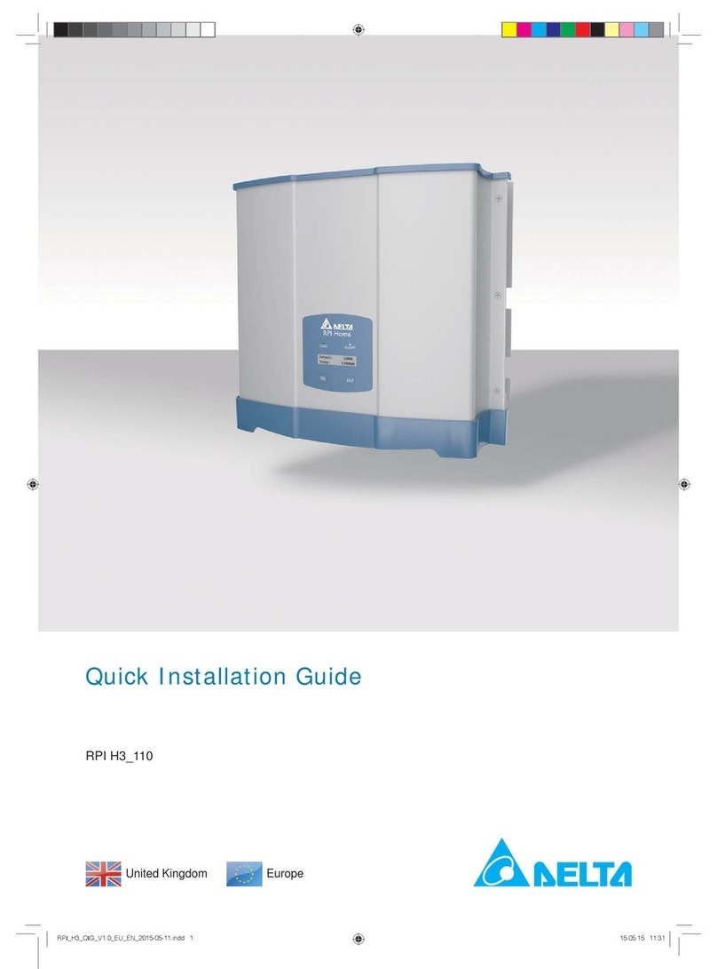
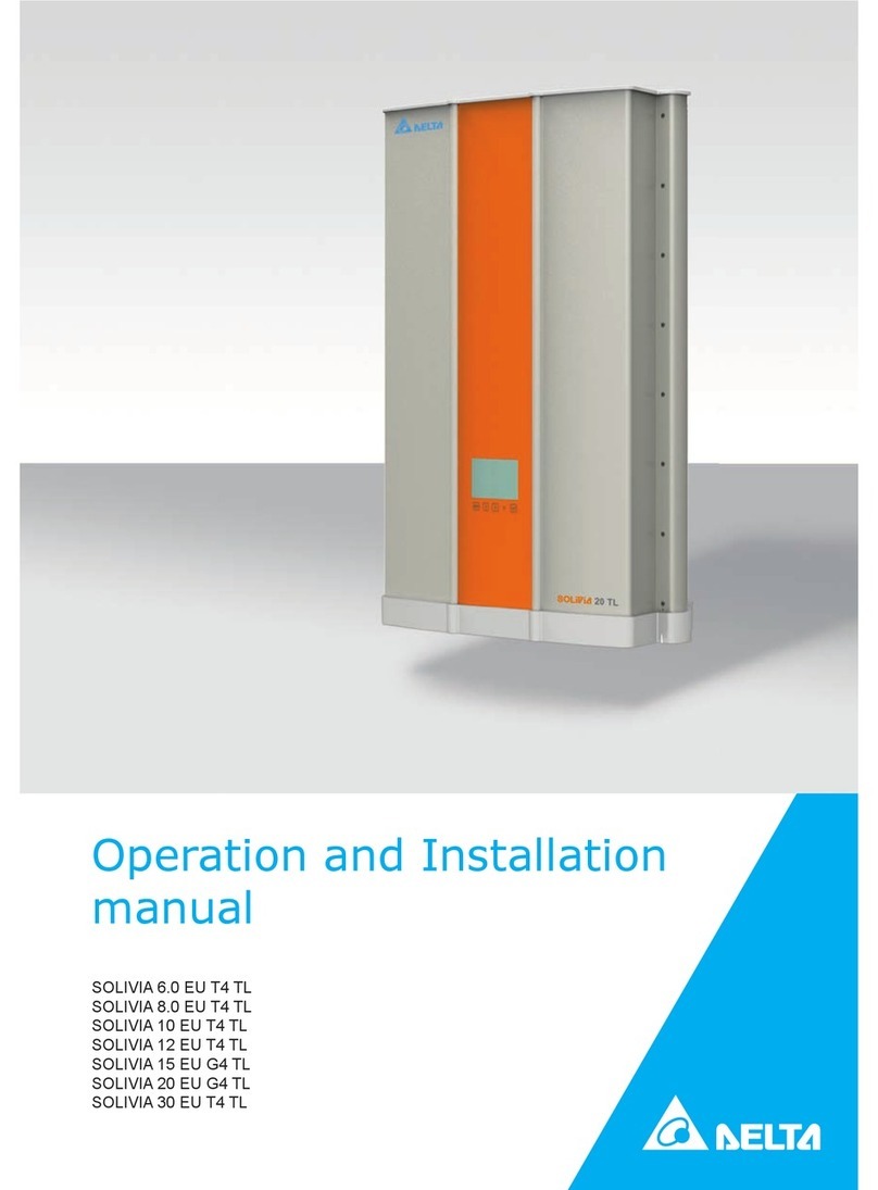
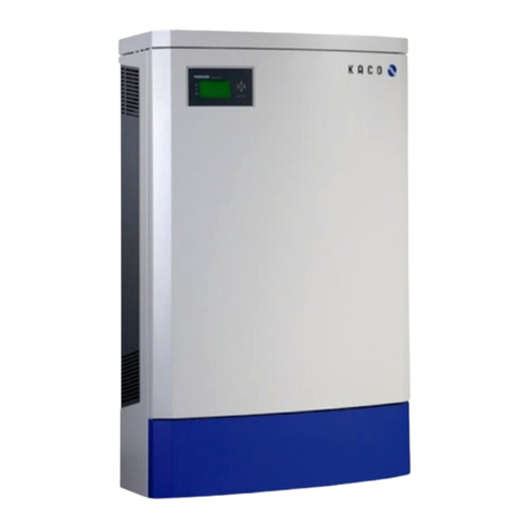
Delta Energy Systems Solivia 3.6 EU G4 TR Specification sheet

Operation and Installation Manual for
SOLIVIA 2.0 EU G4 TR
SOLIVIA 2.5 EU G4 TR
SOLIVIA 3.0 EU G4 TR
SOLIVIA 3.3 EU G4 TR
SOLIVIA 3.6 EU G4 TR
SOLIVIA 5.0 EU G4 TR

Operation and Installation Manual for SOLIVIA 2.0/2.5/3.0/3.3/3.6/5.0 EU G4 TR
2
This manual applies to the following solar inverter types:
●SOLIVIA 2.0 EU G4 TR
●SOLIVIA 2.5 EU G4 TR
●SOLIVIA 3.0 EU G4 TR
●SOLIVIA 3.3 EU G4 TR
●SOLIVIA 3.6 EU G4 TR
●SOLIVIA 5.0 EU G4 TR
This manual can be amended at any time.
The latest version of this manual is available at www.solar-inverter.
com.
Delta Energy Systems (Germany) GmbH
Tscheulinstraße 21
79331 Teningen
Germany
© Copyright – Delta Energy Systems (Germany) GmbH – All rights
reserved.
This manual is included with our solar inverter and is intended for
use by the installer and end user.
The technical instructions and illustrations in this manual are to be
treated as condential and no part of this manual may be repro-
duced without prior written permission from Delta Energy Systems.
Maintenance technicians and end users may not release the infor-
mation contained in this manual, and may not use it for purposes
not directly associated with the proper use of the solar inverter.
All information and specications can be modied without prior
notice.

3
Operation and Installation Manual for SOLIVIA 2.0/2.5/3.0/3.3/3.6/5.0 EU G4 TR
Table of Contents
Table of Contents
1. About This Manual . . . . . . . . . . . . . . . . . . . . . . . . . . . . . . . . . . . . . . . . . . . . . . . . . . . . 6
1.1 Purpose of This Manual . . . . . . . . . . . . . . . . . . . . . . . . . . . . . . . . . . . . . . . . . . . . . . 6
1.2 Target audience of this manual . . . . . . . . . . . . . . . . . . . . . . . . . . . . . . . . . . . . . . . . . . 6
1.3 Warnings and Symbols. . . . . . . . . . . . . . . . . . . . . . . . . . . . . . . . . . . . . . . . . . . . . . . 6
1.4 Conventions Used in This Document . . . . . . . . . . . . . . . . . . . . . . . . . . . . . . . . . . . . . . . 6
1.4.1 Order of Instructions . . . . . . . . . . . . . . . . . . . . . . . . . . . . . . . . . . . . . . . . . . 6
1.4.2 User buttons and LEDs . . . . . . . . . . . . . . . . . . . . . . . . . . . . . . . . . . . . . . . . 6
1.4.3 Information on Display . . . . . . . . . . . . . . . . . . . . . . . . . . . . . . . . . . . . . . . . . 6
2. Intended purpose . . . . . . . . . . . . . . . . . . . . . . . . . . . . . . . . . . . . . . . . . . . . . . . . . . . . . 7
3. General Safety Instructions . . . . . . . . . . . . . . . . . . . . . . . . . . . . . . . . . . . . . . . . . . . . . . . 9
4. Unpacking . . . . . . . . . . . . . . . . . . . . . . . . . . . . . . . . . . . . . . . . . . . . . . . . . . . . . . . . 10
5. Product Description . . . . . . . . . . . . . . . . . . . . . . . . . . . . . . . . . . . . . . . . . . . . . . . . . . .11
5.1 Overview of Components and Connections . . . . . . . . . . . . . . . . . . . . . . . . . . . . . . . . . . . .11
5.2 Type Plate . . . . . . . . . . . . . . . . . . . . . . . . . . . . . . . . . . . . . . . . . . . . . . . . . . . . 12
5.3 Status LEDs . . . . . . . . . . . . . . . . . . . . . . . . . . . . . . . . . . . . . . . . . . . . . . . . . . . 14
5.4 Display and Buttons . . . . . . . . . . . . . . . . . . . . . . . . . . . . . . . . . . . . . . . . . . . . . . . 14
5.4.1 Overview . . . . . . . . . . . . . . . . . . . . . . . . . . . . . . . . . . . . . . . . . . . . . . . 14
5.4.2 Display Layout . . . . . . . . . . . . . . . . . . . . . . . . . . . . . . . . . . . . . . . . . . . . 14
5.4.3 Buttons . . . . . . . . . . . . . . . . . . . . . . . . . . . . . . . . . . . . . . . . . . . . . . . . 14
5.4.4 General Menu Structure . . . . . . . . . . . . . . . . . . . . . . . . . . . . . . . . . . . . . . . 14
5.4.5 "Go to Menu" function . . . . . . . . . . . . . . . . . . . . . . . . . . . . . . . . . . . . . . . . 15
5.4.6 Button combinations . . . . . . . . . . . . . . . . . . . . . . . . . . . . . . . . . . . . . . . . . 15
5.4.7 Navigating the Menu . . . . . . . . . . . . . . . . . . . . . . . . . . . . . . . . . . . . . . . . . 15
5.4.8 Selecting a Submenu . . . . . . . . . . . . . . . . . . . . . . . . . . . . . . . . . . . . . . . . 15
5.4.9 Exiting a Menu . . . . . . . . . . . . . . . . . . . . . . . . . . . . . . . . . . . . . . . . . . . 15
5.4.10 Setting Values . . . . . . . . . . . . . . . . . . . . . . . . . . . . . . . . . . . . . . . . . . . . 16
5.5 Electrical Connections . . . . . . . . . . . . . . . . . . . . . . . . . . . . . . . . . . . . . . . . . . . . . . 18
5.5.1 Overview . . . . . . . . . . . . . . . . . . . . . . . . . . . . . . . . . . . . . . . . . . . . . . . 18
5.5.2 DC connections and DC isolating switch . . . . . . . . . . . . . . . . . . . . . . . . . . . . . . 20
5.5.3 AC connection
. . . . . . . . . . . . . . . . . . . . . . . . . . . . . . . . . . . . . . . . . . . . 20
5.5.4 RS485 interface (EIA485) . . . . . . . . . . . . . . . . . . . . . . . . . . . . . . . . . . . . . . 20
5.5.5 USB interface . . . . . . . . . . . . . . . . . . . . . . . . . . . . . . . . . . . . . . . . . . . . 20
6. Operating Behavior . . . . . . . . . . . . . . . . . . . . . . . . . . . . . . . . . . . . . . . . . . . . . . . . . . . 21
6.1 General Principle of Operation . . . . . . . . . . . . . . . . . . . . . . . . . . . . . . . . . . . . . . . . . . 21
6.2 Impact of DC Input Voltage . . . . . . . . . . . . . . . . . . . . . . . . . . . . . . . . . . . . . . . . . . . 21
6.3 Conguring Permanent Active and Reactive Power Reduction . . . . . . . . . . . . . . . . . . . . . . . . . 21
6.4 Functions Affecting Operating Behavior . . . . . . . . . . . . . . . . . . . . . . . . . . . . . . . . . . . . . 21
6.5 Balancing Asymmetrical Grid Loads . . . . . . . . . . . . . . . . . . . . . . . . . . . . . . . . . . . . . . . 21
6.6 Data Analysis and Communication. . . . . . . . . . . . . . . . . . . . . . . . . . . . . . . . . . . . . . . . 21
6.7 Characteristic Curves . . . . . . . . . . . . . . . . . . . . . . . . . . . . . . . . . . . . . . . . . . . . . . 23
7. Installation. . . . . . . . . . . . . . . . . . . . . . . . . . . . . . . . . . . . . . . . . . . . . . . . . . . . . . . . 24
7.1 Planning the Installation . . . . . . . . . . . . . . . . . . . . . . . . . . . . . . . . . . . . . . . . . . . . . 24
7.1.1 General Instructions . . . . . . . . . . . . . . . . . . . . . . . . . . . . . . . . . . . . . . . . . 24
7.1.2 Ambient Conditions . . . . . . . . . . . . . . . . . . . . . . . . . . . . . . . . . . . . . . . . . 25
7.1.3 Consideration of Asymmetrical Grid Load . . . . . . . . . . . . . . . . . . . . . . . . . . . . . . 25
7.2 Mounting Solar Inverter . . . . . . . . . . . . . . . . . . . . . . . . . . . . . . . . . . . . . . . . . . . . . 27
7.2.1 Required Tools and Accessories . . . . . . . . . . . . . . . . . . . . . . . . . . . . . . . . . . . 27
7.2.2 Installing Mounting Plate . . . . . . . . . . . . . . . . . . . . . . . . . . . . . . . . . . . . . . . 27
7.2.3 Mounting Solar Inverter . . . . . . . . . . . . . . . . . . . . . . . . . . . . . . . . . . . . . . . 28

Operation and Installation Manual for SOLIVIA 2.0/2.5/3.0/3.3/3.6/5.0 EU G4 TR
4
Table of Contents
7.3 Grid Connection . . . . . . . . . . . . . . . . . . . . . . . . . . . . . . . . . . . . . . . . . . . . . . . . . 28
7.3.1 General Instructions . . . . . . . . . . . . . . . . . . . . . . . . . . . . . . . . . . . . . . . . . 28
7.3.2 Required Tools and Accessories . . . . . . . . . . . . . . . . . . . . . . . . . . . . . . . . . . . 29
7.3.3 Establishing Connection . . . . . . . . . . . . . . . . . . . . . . . . . . . . . . . . . . . . . . . 29
7.4 Connecting the PV Modules . . . . . . . . . . . . . . . . . . . . . . . . . . . . . . . . . . . . . . . . . . . 30
7.4.1 General Instructions . . . . . . . . . . . . . . . . . . . . . . . . . . . . . . . . . . . . . . . . . 30
7.4.2 Required Tools and Accessories . . . . . . . . . . . . . . . . . . . . . . . . . . . . . . . . . . . 31
7.4.3 Establishing Connection . . . . . . . . . . . . . . . . . . . . . . . . . . . . . . . . . . . . . . . 31
7.4.4 Grounding DC Side . . . . . . . . . . . . . . . . . . . . . . . . . . . . . . . . . . . . . . . . . 32
7.5 Connecting RS485 (EIA485) - Optional . . . . . . . . . . . . . . . . . . . . . . . . . . . . . . . . . . . . . 32
7.5.1 General Instructions . . . . . . . . . . . . . . . . . . . . . . . . . . . . . . . . . . . . . . . . . 32
7.5.2 Required Tools and Accessories . . . . . . . . . . . . . . . . . . . . . . . . . . . . . . . . . . . 33
7.5.3 Connecting Individual Solar Inverters . . . . . . . . . . . . . . . . . . . . . . . . . . . . . . . . 33
7.5.4 Connecting Multiple Solar Inverters . . . . . . . . . . . . . . . . . . . . . . . . . . . . . . . . . 33
8. Commissioning . . . . . . . . . . . . . . . . . . . . . . . . . . . . . . . . . . . . . . . . . . . . . . . . . . . . . 34
8.1 Before You Begin. . . . . . . . . . . . . . . . . . . . . . . . . . . . . . . . . . . . . . . . . . . . . . . . . 34
8.2 Selecting the Correct Commissioning Procedure . . . . . . . . . . . . . . . . . . . . . . . . . . . . . . . . 34
8.3 Commissioning for EN 50438 and VDE 0126 Grids . . . . . . . . . . . . . . . . . . . . . . . . . . . . . . . 35
8.4 Commissioning for VDE AR N 4105 Grids . . . . . . . . . . . . . . . . . . . . . . . . . . . . . . . . . . . . 38
8.5 Commissioning in Italy for PV Systems Below 6 kW. . . . . . . . . . . . . . . . . . . . . . . . . . . . . . . 41
8.6 Commissioning by Loading Settings from Other Solar Inverter . . . . . . . . . . . . . . . . . . . . . . . . . 44
8.7 Commissioning After Replacing Solar Inverter. . . . . . . . . . . . . . . . . . . . . . . . . . . . . . . . . . 47
9. Production Information . . . . . . . . . . . . . . . . . . . . . . . . . . . . . . . . . . . . . . . . . . . . . . . . . 50
9.1 Overview . . . . . . . . . . . . . . . . . . . . . . . . . . . . . . . . . . . . . . . . . . . . . . . . . . . . . 50
9.2 Current Data . . . . . . . . . . . . . . . . . . . . . . . . . . . . . . . . . . . . . . . . . . . . . . . . . . . 50
9.3 Other Statistics . . . . . . . . . . . . . . . . . . . . . . . . . . . . . . . . . . . . . . . . . . . . . . . . . . 50
9.4 Deleting Statistics . . . . . . . . . . . . . . . . . . . . . . . . . . . . . . . . . . . . . . . . . . . . . . . . 51
10. Settings . . . . . . . . . . . . . . . . . . . . . . . . . . . . . . . . . . . . . . . . . . . . . . . . . . . . . . . . . 52
10.1 Overview . . . . . . . . . . . . . . . . . . . . . . . . . . . . . . . . . . . . . . . . . . . . . . . . . . . . . 52
10.2 Display language. . . . . . . . . . . . . . . . . . . . . . . . . . . . . . . . . . . . . . . . . . . . . . . . . 52
10.3 Date and time . . . . . . . . . . . . . . . . . . . . . . . . . . . . . . . . . . . . . . . . . . . . . . . . . . 53
10.4 Date and time formats . . . . . . . . . . . . . . . . . . . . . . . . . . . . . . . . . . . . . . . . . . . . . . 53
10.5 Backlighting, contrast . . . . . . . . . . . . . . . . . . . . . . . . . . . . . . . . . . . . . . . . . . . . . . 54
10.6 RS485 (EIA485) Settings . . . . . . . . . . . . . . . . . . . . . . . . . . . . . . . . . . . . . . . . . . . . 54
10.7 Currency and Credit per kWh . . . . . . . . . . . . . . . . . . . . . . . . . . . . . . . . . . . . . . . . . . 55
10.8 Reset Statistics. . . . . . . . . . . . . . . . . . . . . . . . . . . . . . . . . . . . . . . . . . . . . . . . . . 55
10.9 Active Power Control. . . . . . . . . . . . . . . . . . . . . . . . . . . . . . . . . . . . . . . . . . . . . . . 56
10.9.1 Overview . . . . . . . . . . . . . . . . . . . . . . . . . . . . . . . . . . . . . . . . . . . . . . . 56
10.9.2 Active Power Reduction . . . . . . . . . . . . . . . . . . . . . . . . . . . . . . . . . . . . . . . 56
10.9.3 Active Power by Frequency P(f) . . . . . . . . . . . . . . . . . . . . . . . . . . . . . . . . . . . 57
10.10 Reactive Power Control . . . . . . . . . . . . . . . . . . . . . . . . . . . . . . . . . . . . . . . . . . . . . 58
10.10.1 Overview . . . . . . . . . . . . . . . . . . . . . . . . . . . . . . . . . . . . . . . . . . . . . . . 58
10.10.2 Power Factor by Active Power cos φ (P). . . . . . . . . . . . . . . . . . . . . . . . . . . . . . . 58
10.10.3 Constant Power Factor cos φ . . . . . . . . . . . . . . . . . . . . . . . . . . . . . . . . . . . . 60
10.11 Local Control (Italy only) . . . . . . . . . . . . . . . . . . . . . . . . . . . . . . . . . . . . . . . . . . . . . 60
10.12 Shading (extended MPP tracker) . . . . . . . . . . . . . . . . . . . . . . . . . . . . . . . . . . . . . . . . 61
10.13 Insulation and grounding monitoring . . . . . . . . . . . . . . . . . . . . . . . . . . . . . . . . . . . . . . . 61
10.14 Standard menu. . . . . . . . . . . . . . . . . . . . . . . . . . . . . . . . . . . . . . . . . . . . . . . . . . 62
10.15 Changing Grid . . . . . . . . . . . . . . . . . . . . . . . . . . . . . . . . . . . . . . . . . . . . . . . . . . 62

5
Operation and Installation Manual for SOLIVIA 2.0/2.5/3.0/3.3/3.6/5.0 EU G4 TR
Table of Contents
11. Saving and Loading Data and Settings . . . . . . . . . . . . . . . . . . . . . . . . . . . . . . . . . . . . . . . . 63
11.1 Before You Begin. . . . . . . . . . . . . . . . . . . . . . . . . . . . . . . . . . . . . . . . . . . . . . . . . 63
11.2 Organize les . . . . . . . . . . . . . . . . . . . . . . . . . . . . . . . . . . . . . . . . . . . . . . . . . . 63
11.3 Firmware Updating . . . . . . . . . . . . . . . . . . . . . . . . . . . . . . . . . . . . . . . . . . . . . . . . 64
11.4 Saving Settings . . . . . . . . . . . . . . . . . . . . . . . . . . . . . . . . . . . . . . . . . . . . . . . . . 65
11.5 Loading Settings . . . . . . . . . . . . . . . . . . . . . . . . . . . . . . . . . . . . . . . . . . . . . . . . . 66
11.6 Saving Swap Data . . . . . . . . . . . . . . . . . . . . . . . . . . . . . . . . . . . . . . . . . . . . . . . . 67
11.7 Creating Reports . . . . . . . . . . . . . . . . . . . . . . . . . . . . . . . . . . . . . . . . . . . . . . . . . 68
11.8 Service . . . . . . . . . . . . . . . . . . . . . . . . . . . . . . . . . . . . . . . . . . . . . . . . . . . . . . 68
12. Diagnostics and Troubleshooting . . . . . . . . . . . . . . . . . . . . . . . . . . . . . . . . . . . . . . . . . . . 69
12.1 Messages on Current Operating Status . . . . . . . . . . . . . . . . . . . . . . . . . . . . . . . . . . . . . 69
12.2 Analyzing Failures . . . . . . . . . . . . . . . . . . . . . . . . . . . . . . . . . . . . . . . . . . . . . . . . 71
12.2.1 Procedure for External Events . . . . . . . . . . . . . . . . . . . . . . . . . . . . . . . . . . . . 71
12.2.2 Procedure for Internal Events . . . . . . . . . . . . . . . . . . . . . . . . . . . . . . . . . . . . 72
12.3 Overview of Failure Messages/Troubleshooting . . . . . . . . . . . . . . . . . . . . . . . . . . . . . . . . . 73
12.4 Message Logs . . . . . . . . . . . . . . . . . . . . . . . . . . . . . . . . . . . . . . . . . . . . . . . . . . 75
12.4.1 "External events" log . . . . . . . . . . . . . . . . . . . . . . . . . . . . . . . . . . . . . . . . . 75
12.4.2 "Internal Events" Log. . . . . . . . . . . . . . . . . . . . . . . . . . . . . . . . . . . . . . . . . 75
12.4.3 Log for VDE AR N 4105 . . . . . . . . . . . . . . . . . . . . . . . . . . . . . . . . . . . . . . . 76
12.4.4 "Change Events" Log . . . . . . . . . . . . . . . . . . . . . . . . . . . . . . . . . . . . . . . . 76
12.5 Current Grid Settings. . . . . . . . . . . . . . . . . . . . . . . . . . . . . . . . . . . . . . . . . . . . . . . 77
12.6 Autotest for Italy . . . . . . . . . . . . . . . . . . . . . . . . . . . . . . . . . . . . . . . . . . . . . . . . . 77
13. Maintenance and Repair . . . . . . . . . . . . . . . . . . . . . . . . . . . . . . . . . . . . . . . . . . . . . . . . 79
14. Decommissioning, Transport, Storage, Disposal. . . . . . . . . . . . . . . . . . . . . . . . . . . . . . . . . . . 79
14.1 Decommissioning . . . . . . . . . . . . . . . . . . . . . . . . . . . . . . . . . . . . . . . . . . . . . . . . 79
14.2 Packaging . . . . . . . . . . . . . . . . . . . . . . . . . . . . . . . . . . . . . . . . . . . . . . . . . . . . 79
14.3 Transport . . . . . . . . . . . . . . . . . . . . . . . . . . . . . . . . . . . . . . . . . . . . . . . . . . . . . 79
14.4 Storage. . . . . . . . . . . . . . . . . . . . . . . . . . . . . . . . . . . . . . . . . . . . . . . . . . . . . . 79
14.5 Disposal . . . . . . . . . . . . . . . . . . . . . . . . . . . . . . . . . . . . . . . . . . . . . . . . . . . . . 79
15.TechnicalSpecications . . . . . . . . . . . . . . . . . . . . . . . . . . . . . . . . . . . . . . . . . . . . . . . . 80
16. Appendix . . . . . . . . . . . . . . . . . . . . . . . . . . . . . . . . . . . . . . . . . . . . . . . . . . . . . . . . 82
16.1 Order numbers . . . . . . . . . . . . . . . . . . . . . . . . . . . . . . . . . . . . . . . . . . . . . . . . . . 82
16.2 Overview of Menu Structure . . . . . . . . . . . . . . . . . . . . . . . . . . . . . . . . . . . . . . . . . . . 83

1. About This Manual
Operation and Installation Manual for SOLIVIA 2.0/2.5/3.0/3.3/3.6/5.0 EU G4 TR
6
1. About This Manual
This manual will help you become familiar with the solar inverter.
Observe the safety regulations applicable for each country. You can
help keep the product durable and reliable during its use by han-
dling it carefully. These are the basic requirements for optimal use
of the solar inverter.
1.1 Purpose of This Manual
This manual is part of the product. Store the manual in a safe
place.
Read the manual carefully and thoroughly and follow the instruc-
tions contained therein. This manual contains important informa-
tion on the installation, commissioning and operation of the solar
inverter.
Observe this information for safe use (see “3 General Safety
Instructions”, p. 9).
The installer and the operator must have access to this manual and
must be familiar with the safety instructions.
The solar inverter can be safely and normally operated if installed
and used in accordance with this manual. Delta Energy Systems is
not responsible for damage incurred by failure to comply with the
installation and operating instructions in this manual.
1.2 Target audience of this manual
This manual is aimed at qualied electricians.
Only Chapters “9 Production Information”, p. 50 and “12 Diag-
nostics and Troubleshooting”, p. 69 pertain to the user. All other
activities may only be performed by qualied electricians.
1.3 Warnings and Symbols
The following section explains the warnings and symbols used in
this manual.
DANGER
Indicates an extremely hazardous situation. An accident
will result in death or serious injury.
WARNING
Indicates a very hazardous situation. An accident can
result in death or serious injury.
CAUTION
Indicates a hazardous situation. An accident can result in
mild to moderate injury.
ATTENTION
Indicates a hazardous situation that can result in property
damage.
NOTE
Contains general information on using the solar inverter. A
note does not indicate hazardous situations.
This symbol warns of a risk of electric shock due
to high voltage.
This symbol is a warning of general hazards.
1.4 Conventions Used in This Document
1.4.1 Order of Instructions
Numbered instructions must be performed in the specied order.
1. Step
→When the solar inverter reacts to a step, this reaction is
marked with an arrow.
2. Step
3. Step
The end of instructions is designated as follows:
þEnd of instructions
Instructions consisting of only one step are shown as follows:
►Step
1.4.2 User buttons and LEDs
User buttons and LEDs are shown in this document as follows:
User buttons on solar inverter:
ESC
button.
LEDs on solar inverter: Failure LED
LED symbol Meaning
LED stays on.
LED ashes.
LED is off.
1.4.3 Information on Display
Information shown on the solar inverter display includes menus,
settings and messages.
This information is shown in this manual as follows:
Menu names: User settings menu
Parameter names: Cos phi parameter.

7
Operation and Installation Manual for SOLIVIA 2.0/2.5/3.0/3.3/3.6/5.0 EU G4 TR
2. Intended purpose
EN
2. Intended purpose
This EU-series solar inverter may be used in the following coun-
tries:
NOTE
This list may change due to ongoing certication
processes. If you have any questions, please
contact the Delta Support Team.
Country Standard SOLIVIA
2.0 2.5 3.0 3.3 3.6 5.0
Belgium Synergrid C10/11 2012 x x x x x x
Bulgaria VDE 0126 x x x x x
Czech Republic x x x x x
Denmark VDE AR 4105 xxxxxx
France French islands 60 Hz, UTE 15 712-1 x x x x x
Germany VDE AR 4105 xxxxxx
Great Britain G59-2 230 V + 240 V x x x x x x
G83-1 x x x x x
Greece Greece/islands, Greece/continent x x x x x
Italy CEI 0-21:2012.06 for PV systems ≤ 6 kW xxxxx
CEI 0-21:2012.06 for PV systems > 6 kW x x x x x
Netherlands VDE 0126 + EN 50438 x x x x x x
Poland EN 50438
Portugal EN 50438 x x x x x
Romania VDE 0126 x x x x
Slovakia VDE 0126 x x x x x
Spain Spanish islands, RD661, RD1699 x x x x x
The solar inverter may only be used as intended.
Proper use of the solar inverter meets the following criteria:
●Use in stationary PV systems connected to the local power
grid for converting the direct current in the PV system to alter-
nating current and feeding it into the grid
● Use within the specied power range (see “15 Technical Speci-
cations”, p. 80) and under the specied ambient conditions
(indoor area or covered outdoor area with up to IP65)
Any of the following uses of the solar inverter is considered
improper:
●Isolated operation The solar inverter has anti-islanding and
other monitoring features.
●Use in mobile PV systems.

2. Intended purpose
Operation and Installation Manual for SOLIVIA 2.0/2.5/3.0/3.3/3.6/5.0 EU G4 TR
8

9
Operation and Installation Manual for SOLIVIA 2.0/2.5/3.0/3.3/3.6/5.0 EU G4 TR
3. General Safety Instructions
EN
3. General Safety Instructions
DANGER
Risk of death by electrocution
Potentially fatal voltage is applied to the solar
inverter during operation. This potentially fatal
voltage is still present for ve minutes after all
power sources have been disconnected.
►Never open the solar inverter.
►Always disconnect the solar inverter from
power before installation, open the DC isolat-
ing switch and make sure neither can be
accidentally reconnected.
► Wait at least ve minutes until the capacitors
have discharged.
DANGER
Risk of death or serious injury from electro-
cution
Potentially fatal voltage may be applied to the DC
connections of the solar inverter.
►Never disconnect the PV modules when the
solar inverter is powered.
►First switch off the grid connection so that
the solar inverter cannot feed energy into the
grid.
►Then open the DC isolating switch.
►Make sure the DC connections cannot be
accidentally touched.
●The solar inverter can be safely and normally operated if
installed and used in accordance with this manual (see
IEC 62109-5.3.3). Delta Energy Systems is not responsible
for damage incurred by failure to observe the installation and
operating instructions in this manual. For this reason, be sure
to observe and follow all instructions!
●Installation and commissioning may only be performed by
qualied electricians using the installation and commissioning
instructions found in this manual.
●The solar inverter must be disconnected from power and the
PV modules before any work on it can be performed.
●The solar inverter has a high leakage current value (see
“15 Technical Specications”, p. 80). The ground wire must
be connected before commissioning.
●Do not remove any warning signs that the manufacturer has
installed on the solar inverter.
●Improper handling of the solar inverter my result in physical
injury and damage to property. For this reason, observe and
follow all general safety instructions and warnings.
●The solar inverter contains no components that must be main-
tained or repaired by the operator or installer. All repairs must
be performed by Delta Energy Systems. Opening the cover
will void the warranty.
●Do not disconnect any cables when the solar inverter is pow-
ered due to risk of a fault arc.
●To prevent lightning strikes, follow the relevant regulations ap-
plicable in your country.
●The surface of the solar inverter can become very hot.
●The solar inverter is very heavy (see “15 Technical Specica-
tions”, p. 80). The solar inverter must be lifted and carried
by at least two people.
●Only devices in compliance with SELV (EN 69050) may be
connected to the RS485 and USB interfaces.
● All connections must be sufciently insulated in order to com-
ply with the IP65 protection rating. Unused connections must
be closed by placing cover caps on the solar inverter.

4. Unpacking
Operation and Installation Manual for SOLIVIA 2.0/2.5/3.0/3.3/3.6/5.0 EU G4 TR
10
4. Unpacking
WARNING
Risk of injury due to weight
The weight of the solar inverter (see “15 Techni-
cal Specications”, p. 80) can cause injury if
not handled properly.
►The solar inverter must be lifted and carried
by at least two people.
(b)
(e)
(c) (d)
(f)
➀
➁
➂
➄
➅
►Check the scope of delivery for completeness:
– Mounting plate (a)
– Operation and installation manual (b)
– Wieland RST25i3S AC plug (c)
– 2 M6 nuts and 2 M6 washers (d)
– "Power limit" label (e)
– Solar inverter (f)
►Check all parts for signs of damage!
►Store the packaging in a safe place!
(a)
➃

11
Operation and Installation Manual for SOLIVIA 2.0/2.5/3.0/3.3/3.6/5.0 EU G4 TR
5. Product Description
EN
5. Product Description
5.1 Overview of Components and Connections
➀
➁
➃
➂
Fig. 5.1: Solar Inverter Components and Connections
No. Component/Connection Description
➀Status LEDs See Chapter “5.3 Status LEDs”, p. 14
➁Display and Buttons See Chapter “5.4 Display and Buttons”, p. 14
➂Type Plate See Chapter “5.2 Type Plate”, p. 12
➃Electrical Connections See Chapter “5.5 Electrical Connections”, p. 18

5. Product Description
Operation and Installation Manual for SOLIVIA 2.0/2.5/3.0/3.3/3.6/5.0 EU G4 TR
12
5.2 Type Plate
AC nom. output voltage:
AC nom. output frequency:
AC max. continuous output current:
AC max. continuous output power:
AC power factor
DC operating volt. range:
DC operating volt. range (MPP):
DC max. input voltage:
DC max. operating current:
DC max. current per string:
XX
YYWW
LLLMMMXXYYWWZZZZZZ
www.solar-inverter.com
Designed in: Germany
Made in: production plant
Rev:
Date code:
S/N:
SOLIVIA2.0EUG4TR
EOE45010459
SN: LLLMMMXXYYWWZZZZZZ
125-600V
150-480V
600V
15A
17A
230V
50Hz
11.0A
2000VA
Cap 0.8~Ind 0.8
VDE 0126-1-1 (D)
VDE-AR-N-4105
Country specific standards and settings:
see manual
IP class: IP65
Safety class:1
Ambient temp: -25°C...+70°C, derating >55°C
5min.
Fig. 5.2: SOLIVIA 2.0 EU G4 TR type plate
AC nom.output voltage:
AC nom.output frequency:
AC max. continuous output current:
AC max. continuous output power:
AC power factor
DC operating volt. range:
DC operating volt. range (MPP):
DC max. input voltage:
DC max. operating current:
DC max. current per string:
XX
YYWW
LLLMMMXXYYWWZZZZZZ
www.solar-inverter.com
Designed in: Germany
Made in: production plant
Rev:
Date code:
S/N:
SOLIVIA2.5EUG4
EOE46010288
SN: LLLMMMXXYYWWZZZZZZ
125-600V
150-480V
600V
18.2A
17A
230V
50Hz
15.5A
2500VA
Cap 0.8~Ind 0.8
VDE 0126-1-1 (D)
VDE-AR-N-4105
Country specific standards and settings:
see manual
IP class: IP65
Safety class: 1
Ambient temp: -25°C...+70°C, derating >55°C
5min.
Fig. 5.3: SOLIVIA 2.5 EU G4 TR type plate
AC nom.output voltage:
AC nom.output frequency:
AC max. continuous output current:
AC max. continuous output power:
AC power factor:
DC operating volt. range:
DC operating volt. range (MPP):
DC max. input voltage:
DC max. operating current:
DC max. current per string:
XX
YYWW
LLLMMMXXYYWWZZZZZZ
www.solar-inverter.com
Designed in: Germany
Made in: production plant
Rev:
Date code:
S/N:
SOLIVIA3.0EUG4
EOE46010287
SN: LLLMMMXXYYWWZZZZZZ
125-600V
150-480V
600V
22.0A
17A
230V
50Hz
15.5A
3000VA
Cap 0.8~Ind 0.8
VDE 0126-1-1 (D)
VDE-AR-N-4105
Country specific standards and settings:
see manual
IP class: IP65
Safety class: 1
Ambient temp: -25°C...+70°C, derating >55°C
5min.
Fig. 5.4: SOLIVIA 3.0 EU G4 TR type plate
AC nom.output voltage:
AC nom.output frequency:
AC max. continuous output current:
AC max. continuous output power:
AC power factor:
DC operating volt. range:
DC operating volt. range (MPP):
DC max. input voltage:
DC max. operating current:
DC max. current per string:
XX
YYWW
LLLMMMXXYYWWZZZZZZ
www.solar-inverter.com
Designed in: Germany
Made in: production plant
Rev:
Date code:
S/N:
SOLIVIA3.3EUG4TR
EOE46010252
SN: LLLMMMXXYYWWZZZZZZ
125-600V
150-480V
600V
24.0A
17A
230V
50Hz
15.5A
3300VA
Cap 0.8~Ind 0.8
VDE 0126-1-1 (D)
VDE-AR-N-4105
Country specific standards and settings:
see manual
IP class: IP65
Safety class: 1
Ambient temp: -25°C...+70°C, derating >55°C
5min.
Fig. 5.5: SOLIVIA 3.3 EU G4 TR type plate

13
Operation and Installation Manual for SOLIVIA 2.0/2.5/3.0/3.3/3.6/5.0 EU G4 TR
5. Product Description
EN
AC nom.output voltage:
AC nom.output frequency:
AC max. continuous output current:
AC max. continuous output power:
AC power factor
DC operating volt. range:
DC operating volt. range (MPP):
DC max. input voltage:
DC max. operating current:
DC max. current per string:
XX
YYWW
LLLMMMXXYYWWZZZZZZ
www.solar-inverter.com
Designed in: Germany
Made in: production plant
Rev:
Date code:
S/N:
SOLIVIA3.6EUG4
EOE46010316
125-600V
170-480V
600V
22.0A
17A
230V
50Hz
16.0A
3600VA
Cap 0.8~Ind 0.8
VDE 0126-1-1(D)
VDE-AR-N-4105
Country specific standards and settings:
see manual
IP class: IP65
Safety class: 1
Ambient temp: -25°C...+70°C, derating >55°C
Fig. 5.6: SOLIVIA 3.6 EU G4 TR type plate
AC nom.output voltage:
AC nom.output frequency:
AC max. output current:
AC nom. output power:
DC operating volt. range (MPP):
DC max. input voltage:
DC max. operating current:
DC max. current per string:
XX
YYWW
LLLMMMXXYYWWZZZZZZ
www.solar-inverter.com
Designed in: Germany
Made in: production plant
Rev:
Date code:
S/N:
SOLIVIA5.0EUG4TR
EOE46010253
SN: LLLMMMXXYYWWZZZZZZ
150-480V
600V
37A
18A
230 220V
50 60Hz
27.2 28.5A
5000W
IEC 60950-1
EN 50178
IEC 62103
IEC 62109-1 and IEC 62109-2
Country specific standards and settings:
see manual
IP class: IP65
Safety class: 1
Ambient temp: -20°C...+70°C, derating >55°C
5min
Fig. 5.7: SOLIVIA 5.0 EU G4 TR type plate
Meaning of Information on Type Plate
Warning Symbols on Type Plate Meaning of Warning Symbols
5 min
Risk of death by electrocution
Potentially fatal voltage is present when the solar inverter is in operation that remains for ve
minutes after being disconnected from power.
Never open the solar inverter. The solar inverter contains no components that must be main-
tained or repaired by the operator or installer. Opening the cover will void the warranty.
Read the manual before working with the solar inverter and follow the instructions contained in
the manual.
Risk of injury from high temperatures
When in operation, the housing of the solar inverter can become very hot.
Only touch the housing of the solar inverter (outside of the control panel) with safety gloves.
The control panel itself is protected by a special surface.
DC operating volt. range DC operating volt. range
DC operating volt. range (MPP) DC operating volt. range (MPP)
DC max. input voltage DC max. input voltage
DC max. operating current DC max. operating current
DC max. current per string DC max. current per string
AC nom. output voltage AC nom. output voltage
AC nom. output frequency AC nom. output frequency
AC max. continuous output current AC max. continuous output current
AC max. continuous output power AC max. apparent power
AC power factor AC power factor (cos φ)
IP class IP class
Safety class Safety class
Ambient temperature/derating Ambient temperature/derating

5. Product Description
Operation and Installation Manual for SOLIVIA 2.0/2.5/3.0/3.3/3.6/5.0 EU G4 TR
14
5.3 Status LEDs
Operation
Earth Fault
Failure
➀
➁
➂
Fig. 5.8: Status LEDs
No. Label Designation Color
➀OperatiOn Operation Green
➁earth Fault Earth fault Red
➂Failure Failure Yellow
Information on the LED messages can be found in “12 Diagnostics
and Troubleshooting”, p. 69.
5.4 Display and Buttons
5.4.1 Overview
ESC
➀
➁
Fig. 5.9: Overview of Display and Buttons
No. Designation
➀Display
➁Control Buttons
5.4.2 Display Layout
➔
Display settings
Date and time
Language: English
-------------------
100 Install settings
Fig. 5.10: Display
The display has four rows of 20 characters each.
The rst row contains the name and number of the currently dis-
played menu.
The second to fourth rows show the menu elements.
A small arrow in the third row shows the currently selected menu
item.
5.4.3 Buttons
Symbol Use
ESC
●Exit current menu.
●Cancel value setting.
●Move upwards in menu.
●Set value (increase)
●Move downwards in menu.
●Set a value (decrease).
●Select menu item.
● Open congurable value for editing.
●Finish editing (adopt set value).
5.4.4 General Menu Structure
The menus have up to three levels:
[Main menu]
...
300 USB features
400 Production Info
410 Current Data
411 Current Overview
412 Current Data AC
...
420 Day Statistics
430 Week Statistics
...
500 User Settings
...
Most menu names consist of a three-digit number and a menu title.
An overview of the complete menu structure can be found in Chap-
ter “16.2 Overview of Menu Structure”, p. 83.

15
Operation and Installation Manual for SOLIVIA 2.0/2.5/3.0/3.3/3.6/5.0 EU G4 TR
5. Product Description
EN
5.4.5 "Go to Menu" function
NOTE
You can use the "Go to Menu" function to directly
navigate to a particular menu.
A list of the available menu numbers can be
found in “16.2 Overview of Menu Structure”,
p. 83.
1. To start the Go to Menu function, press the
ESC
button for at
least three seconds.
→Go to Menu opens.
➔
411 Current data
Menu: 411
Go to menu
2. Press the button to enter the menu number.
→ The rst digit ashes.
Use the buttons to set the rst digit of the menu number.
→You can only set menu numbers that actually exist. The
name of the associated menu is displayed in the fourth
display row.
3. Once you have set the rst digit, press the button.
→ The second digit ashes.
4. Enter the second and third digit in the same manner.
5. Press the button.
→The menu corresponding to the entered menu number is
displayed.
5.4.6 Button combinations
The table lists special button combinations for the display buttons.
Buttons Action
ESC
Pressing the
ESC
and buttons at the same time
displays the 100 Install Settings menu where
you can change the display language to be used,
see “10.2 Display language”, p. 52.
Pressing the buttons at the same time
displays 800 Standard Menu, where you can set
the "standard menu", see “10.14 Standard menu”,
p. 62.
5.4.7 Navigating the Menu
Use the buttons to navigate in a menu.
Use the button to move down in the menu, and the button to
move up.
➔
Options
Install settings
-------------------
SOLIVIA ##
➔
USB features
Options
Install settings
-------------------
SOLIVIA ##
➔
USB features
Options
Install settings
-------------------
Production info
SOLIVIA ##
5.4.8 Selecting a Submenu
►In order to open a submenu, press the button.
➔
USB features
Options
Install settings
Production info
User settings
SOLIVIA ##
➔
Day statistics
Current data
-------------------
400 Production info
5.4.9 Exiting a Menu
►Press the
ESC
button to return to the higher menu.
➔
Day statistics
Current data
-------------------
400 Production info
ESC
➔
USB features
Options
Install settings
Production info
User settings
SOLIVIA ##

5. Product Description
Operation and Installation Manual for SOLIVIA 2.0/2.5/3.0/3.3/3.6/5.0 EU G4 TR
16
5.4.10 Setting Values
You can set various parameters on the display. Use the but-
tons to change the parameter values.
The button increases the value of the parameter.
The button decreases the value of the parameter.
The
ESC
button can be used to cancel the setting, and the original
value is then displayed.
The button applies the new parameter value.
The example on the next page illustrates the procedure for chang-
ing the value of a parameter.
Example: Setting the date
Buttons Action Result
ESC
1. Press the
ESC
button until the main menu is displayed.
2. In the main menu, select Install Settings using the buttons.
➔
Options
Install settings
-------------------
SOLIVIA ##
3. Press the button to open 100 Install Settings.
➔
Date and time
Language: English
-------------------
100 Install settings
4. Select Date and Time using the buttons.
➔
Display settings
Date and time
Language: English
-------------------
100 Install settings
5. Press the button to open 110 Date and Time.
➔
Time: 14:26:51
Date: 25.05.2012
-------------------
110 Date and time
6. Select Date using the buttons.
➔
Time: 14:26:51
Date: 25.05.2012
-------------------
110 Date and time
7. Press the button to begin conguration.
→ The digits for the rst value (in this case the month) will ash.
➔
Time: 14:26:51
Date: 25.05.2012
-------------------
110 Date and time
-------------------
-------------------
-------------------
-------------------
-------------------
-------------------
-------------------
-------------------
-------------------
-------------------
-------------------
-------------------
-------------------
-------------------
-------------------
-------------------
-------------------
-------------------
-------------------
110 Date and time
110 Date and time
110 Date and time
110 Date and time
110 Date and time
110 Date and time
110 Date and time
110 Date and time
110 Date and time
110 Date and time
110 Date and time
110 Date and time
110 Date and time
110 Date and time
110 Date and time
110 Date and time
110 Date and time
Time: 14:26:51
Time: 14:26:51
Time: 14:26:51
Time: 14:26:51
Time: 14:26:51
➔
Date: 25.05.2012
Date: 25.05.2012
Date: 25.05.2012
Date: 25.05.2012
Date: 25.05.2012
Date: 25.05.2012
Date: 25.05.2012
Date: 25.05.2012
Date: 25.05.2012
Date: 25.05.2012
Date: 25.05.2012
Date: 25.05.2012
Date: 25.05.2012
Date: 25.05.2012
Date: 25.05.2012
Date: 25.05.2012
Date: 25.05.2012
Time: 14:26:51
Time: 14:26:51
Time: 14:26:51
Time: 14:26:51
Time: 14:26:51
Time: 14:26:51
Time: 14:26:51
Time: 14:26:51
Time: 14:26:51
Time: 14:26:51
Time: 14:26:51
Time: 14:26:51
Time: 14:26:51
Time: 14:26:51
8. Select the month using the buttons.
➔
Time: 14:26:51
Date: 12.05.2012
-------------------
110 Date and time
-------------------
-------------------
-------------------
-------------------
-------------------
-------------------
-------------------
-------------------
-------------------
-------------------
-------------------
-------------------
-------------------
-------------------
-------------------
-------------------
-------------------
-------------------
-------------------
110 Date and time
110 Date and time
110 Date and time
110 Date and time
110 Date and time
110 Date and time
110 Date and time
110 Date and time
110 Date and time
110 Date and time
110 Date and time
110 Date and time
110 Date and time
110 Date and time
110 Date and time
110 Date and time
110 Date and time
Time: 14:26:51
Time: 14:26:51
Time: 14:26:51
Time: 14:26:51
Time: 14:26:51
➔
Date: 12.05.2012
Date: 12.05.2012
Date: 12.05.2012
Date: 12.05.2012
Date: 12.05.2012
Date: 12.05.2012
Date: 12.05.2012
Date: 12.05.2012
Date: 12.05.2012
Date: 12.05.2012
Date: 12.05.2012
Date: 12.05.2012
Date: 12.05.2012
Date: 12.05.2012
Date: 12.05.2012
Date: 12.05.2012
Date: 12.05.2012
Time: 14:26:51
Time: 14:26:51
Time: 14:26:51
Time: 14:26:51
Time: 14:26:51
Time: 14:26:51
Time: 14:26:51
Time: 14:26:51
Time: 14:26:51
Time: 14:26:51
Time: 14:26:51
Time: 14:26:51
Time: 14:26:51
Time: 14:26:51
9. Press the button to apply the new value.
→ The digits for the second value (in this case the day) ash.
➔
Time: 14:26:51
Date: 12.05.2012
-------------------
110 Date and time
-------------------
-------------------
-------------------
-------------------
-------------------
-------------------
-------------------
-------------------
-------------------
-------------------
-------------------
-------------------
-------------------
-------------------
-------------------
-------------------
-------------------
-------------------
-------------------
110 Date and time
110 Date and time
110 Date and time
110 Date and time
110 Date and time
110 Date and time
110 Date and time
110 Date and time
110 Date and time
110 Date and time
110 Date and time
110 Date and time
110 Date and time
110 Date and time
110 Date and time
110 Date and time
110 Date and time
Time: 14:26:51
Time: 14:26:51
Time: 14:26:51
Time: 14:26:51
Time: 14:26:51
➔
Date: 12.05.2012
Date: 12.05.2012
Date: 12.05.2012
Date: 12.05.2012
Date: 12.05.2012
Date: 12.05.2012
Date: 12.05.2012
Date: 12.05.2012
Date: 12.05.2012
Date: 12.05.2012
Date: 12.05.2012
Date: 12.05.2012
Date: 12.05.2012
Date: 12.05.2012
Date: 12.05.2012
Date: 12.05.2012
Date: 12.05.2012
Time: 14:26:51
Time: 14:26:51
Time: 14:26:51
Time: 14:26:51
Time: 14:26:51
Time: 14:26:51
Time: 14:26:51
Time: 14:26:51
Time: 14:26:51
Time: 14:26:51
Time: 14:26:51
Time: 14:26:51
Time: 14:26:51
Time: 14:26:51
10. Select the day using the buttons.
➔
Time: 14:26:51
Date: 12.01.2012
-------------------
110 Date and time
-------------------
-------------------
-------------------
-------------------
-------------------
-------------------
-------------------
-------------------
-------------------
-------------------
-------------------
-------------------
-------------------
-------------------
-------------------
-------------------
-------------------
-------------------
-------------------
110 Date and time
110 Date and time
110 Date and time
110 Date and time
110 Date and time
110 Date and time
110 Date and time
110 Date and time
110 Date and time
110 Date and time
110 Date and time
110 Date and time
110 Date and time
110 Date and time
110 Date and time
110 Date and time
110 Date and time
Time: 14:26:51
Time: 14:26:51
Time: 14:26:51
Time: 14:26:51
Time: 14:26:51
➔
Date: 12.01.2012
Date: 12.01.2012
Date: 12.01.2012
Date: 12.01.2012
Date: 12.01.2012
Date: 12.01.2012
Date: 12.01.2012
Date: 12.01.2012
Date: 12.01.2012
Date: 12.01.2012
Date: 12.01.2012
Date: 12.01.2012
Date: 12.01.2012
Date: 12.01.2012
Date: 12.01.2012
Date: 12.01.2012
Date: 12.01.2012
Time: 14:26:51
Time: 14:26:51
Time: 14:26:51
Time: 14:26:51
Time: 14:26:51
Time: 14:26:51
Time: 14:26:51
Time: 14:26:51
Time: 14:26:51
Time: 14:26:51
Time: 14:26:51
Time: 14:26:51
Time: 14:26:51
Time: 14:26:51
11. Press the button to apply the new value.
→ The digits for the last value (in this case the year) ash.
➔
Time: 14:26:51
Date: 12.01.2012
-------------------
110 Date and time
-------------------
-------------------
-------------------
-------------------
-------------------
-------------------
-------------------
-------------------
-------------------
-------------------
-------------------
-------------------
-------------------
-------------------
-------------------
-------------------
-------------------
-------------------
-------------------
110 Date and time
110 Date and time
110 Date and time
110 Date and time
110 Date and time
110 Date and time
110 Date and time
110 Date and time
110 Date and time
110 Date and time
110 Date and time
110 Date and time
110 Date and time
110 Date and time
110 Date and time
110 Date and time
110 Date and time
Time: 14:26:51
Time: 14:26:51
Time: 14:26:51
Time: 14:26:51
Time: 14:26:51
➔
Date: 12.01.2012
Date: 12.01.2012
Date: 12.01.2012
Date: 12.01.2012
Date: 12.01.2012
Date: 12.01.2012
Date: 12.01.2012
Date: 12.01.2012
Date: 12.01.2012
Date: 12.01.2012
Date: 12.01.2012
Date: 12.01.2012
Date: 12.01.2012
Date: 12.01.2012
Date: 12.01.2012
Date: 12.01.2012
Time: 14:26:51
Time: 14:26:51
Time: 14:26:51
Time: 14:26:51
Time: 14:26:51
Time: 14:26:51
Time: 14:26:51
Time: 14:26:51
Time: 14:26:51
Time: 14:26:51
Time: 14:26:51
Time: 14:26:51
Time: 14:26:51
Time: 14:26:51

17
Operation and Installation Manual for SOLIVIA 2.0/2.5/3.0/3.3/3.6/5.0 EU G4 TR
5. Product Description
EN
Buttons Action Result
12. Select the year using the buttons.
➔
Time: 14:26:51
Date: 12.01.2013
-------------------
110 Date and time
-------------------
-------------------
-------------------
-------------------
-------------------
-------------------
-------------------
-------------------
-------------------
-------------------
-------------------
-------------------
-------------------
-------------------
-------------------
-------------------
-------------------
-------------------
-------------------
110 Date and time
110 Date and time
110 Date and time
110 Date and time
110 Date and time
110 Date and time
110 Date and time
110 Date and time
110 Date and time
110 Date and time
110 Date and time
110 Date and time
110 Date and time
110 Date and time
110 Date and time
110 Date and time
110 Date and time
Time: 14:26:51
Time: 14:26:51
Time: 14:26:51
Time: 14:26:51
Time: 14:26:51
➔
Date: 12.01.2013
Date: 12.01.2013
Date: 12.01.2013
Date: 12.01.2013
Date: 12.01.2013
Date: 12.01.2013
Date: 12.01.2013
Date: 12.01.2013
Date: 12.01.2013
Date: 12.01.2013
Date: 12.01.2013
Date: 12.01.2013
Date: 12.01.2013
Date: 12.01.2013
Date: 12.01.2013
Date: 12.01.2013
Time: 14:26:51
Time: 14:26:51
Time: 14:26:51
Time: 14:26:51
Time: 14:26:51
Time: 14:26:51
Time: 14:26:51
Time: 14:26:51
Time: 14:26:51
Time: 14:26:51
Time: 14:26:51
Time: 14:26:51
Time: 14:26:51
Time: 14:26:51
13. Press the button to apply the new value.
þThe value is adopted and the editing mode is exited.
➔
Time: 14:26:51
Date: 12.01.2013
-------------------
110 Date and time

5. Product Description
Operation and Installation Manual for SOLIVIA 2.0/2.5/3.0/3.3/3.6/5.0 EU G4 TR
18
5.5 Electrical Connections
5.5.1 Overview
➄➃➂
➁➀
Fig. 5.11: Electrical Connections for SOLIVIA 2.0, 2.5 EU G4 TR
➄➃➂
➁➀
Fig. 5.12: Electrical Connections for SOLIVIA 2.0, 2.5, 3.0, 3.3, 3.6 EU G4 TR

19
Operation and Installation Manual for SOLIVIA 2.0/2.5/3.0/3.3/3.6/5.0 EU G4 TR
5. Product Description
EN
➄➃➂➁➀
Fig. 5.13: Electrical Connections for SOLIVIA 5.0 EU G4 TR
No. Designation Description
➀DC connections See Chapter “5.5.2 DC connections and DC isolating switch”, p. 20
➁DC isolating switch See Chapter “5.5.2 DC connections and DC isolating switch”, p. 20
➂USB interface See Chapter “5.5.5 USB interface”, p. 20
➃AC connection See Chapter “5.5.3 AC connection”, p. 20
➄RS485 interfaces See Chapter “5.5.4 RS485 interface (EIA485)”, p. 20

5. Product Description
Operation and Installation Manual for SOLIVIA 2.0/2.5/3.0/3.3/3.6/5.0 EU G4 TR
20
5.5.2 DC connections and DC isolating switch
Fig. 5.14: DC connections and DC isolating switch for
SOLIVIA 2.0, 2.5 EU G4 TR
Fig. 5.15: DC connections and DC isolating switch for SOLIVIA
3.0, 3.3, 3.6 EU G4 TR
Fig. 5.16: DC connections and DC isolating switch for SOLIVIA
5.0 EU G4 TR
The DC connections are used for connecting the PV module
string(s) to the solar inverter.
The integrated DC isolating switch can separate the solar inverter
from the DC voltage of the PV modules.
The maximum permissible input current is 29 A for each DC con-
nection.
Connection type: Multi-contact MC4 plug, paired plug (DC+) and
socket (DC-)
Solar Inverter Number of DC inputs
SOLIVIA 2.0, 2.5 EU G4 TR 2
SOLIVIA 3.0, 3.3, 3.6 EU G4 TR 3
SOLIVIA 5.0 EU G4 TR 4
5.5.3 AC connection
The AC connection is used for connecting the solar inverter to the
grid.
The connection is made using a triple-core cable (L, N, PE).
Connection type: Wieland RST25i3s, plug supplied in the scope of
delivery.
5.5.4 RS485 interface (EIA485)
The solar inverter has two RS485 interfaces to which a PC or a
monitoring system can be connected.
The RS485 interfaces are internally wired 1:1. This means that both
RS485 interfaces can be used as an input or an output.
If multiple solar inverters are connected together, each solar
inverter must have a unique ID (identication number). Monitoring
systems require the ID to recognize each solar inverter in a PV
system.
The last solar inverter must have an RS485 termination resistor
connected, which can be ordered from Delta (see “16.1 Order num-
bers”, p. 82).
The ID can be congured during commissioning (see “8 Commis-
sioning”, p. 34) and can be changed at any time during operation
(see “10.6 RS485 (EIA485) Settings”, p. 54).
Connection type: 2 x RJ45
5.5.5 USB interface
The USB interface is used for saving and loading data and reports.
Supported functions:
● Updating rmware
●Saving and loading settings
●Saving swap data
●Creating reports
●Service
See “11 Saving and Loading Data and Settings”, p. 63 for a
detailed description of the functions.
Connection type: USB A
Table of contents
Other Delta Energy Systems Inverter manuals
Popular Inverter manuals by other brands
SolarMax
SolarMax 3600SP instruction manual
SMA
SMA Sunny Central 500CP-JP installation manual

Islandaire
Islandaire EZ Series Engineering manual
SMA
SMA SUNNY TRIPOWER STORAGE X 30 Quick reference guide
NEP
NEP BDM-300 Installation and operation manual

Spectrum Technologies
Spectrum Technologies 3999WD product manual

Pyle
Pyle Power Inverter PNVU400 owner's manual
NXP Semiconductors
NXP Semiconductors UM11603 user manual
Siemens
Siemens simovert master drive operating instructions

Elenco Electronics
Elenco Electronics FG-500K Assembly and instruction manual
SolarEdge
SolarEdge SEK-AU I Series Quick installation guide
Eltek Valere
Eltek Valere PWS Series user manual
