Hephzibah Veltz Energy SPC-3000S User manual
SPC-3000S
Grid Connected
Solar Inverter
INSTRUCTION MANUAL
072015ver.1

2Your Smart Energy Solution
CONTENTS
Safety Instructions ······································································ 3
Installation Precautions ································································ 4
Precautions in Use ······································································· 5
Product Overview ······································································· 6
Product Specifications ··································································7
Product Features ·········································································8
Block Diagram ············································································ 9
Installation Site ··········································································10
Terminal Connection ···································································10
Wiring ·······················································································11
Display ······················································································14
Operation ··················································································14
Function ····················································································15
Checks and Measures ··································································15
Failures and Corrective Actions ···················································· 16
Warranty ··················································································· 17
Memo ······················································································ 18
▶Thank you for purchasing VELTZ’s Grid Connected Solar Inverter.
Please read this manual before using the product.
▶After reading the manual, keep it at an easily accessible location for users.
▶Be sure to familiarize with ‘Safety Instructions’ for proper usage of product.
▶The product warranty is included in this manual.
▶The specifications of this manual are subject to change without prior notice for
quality improvement.
3
www.veltzenergy.com
Veltz Energy Product Instruction Manual
Safety Instructions
▶The safety instructions are written for you to use the product safely and correctly so as to prevent
accidents or dangers from occurring during product operations. You must comply with these instructions.
▶The precautions are divided into two types: ‘Caution’ and ‘Warning’, which have the following
meanings. You must comply with them for safety purposes.
If you violate these instructions, it may cause serious injury or death.Warning
Warning
Warning
Caution
If you violate these instructions, it may cause slight injury or product damage.
• Do not operate the machine while the front cover is open. The high-voltage terminal or the
charging components are exposed during this time and may cause electric shock.
• Do not operate switches with wet hands. Otherwise, it may cause electric shock.
• Do not open the front cover while power is applied or when the machine is in operation.
Otherwise, it may cause electric shock.
• Even when the power is switched off, do not open the front cover except for during regular
inspections only. Even if the power is disconnected, the voltage is still kept inside the inverter for
a long period of time,
and may cause electric shock if operator comes into contact with the current.
• Before wiring or performing regular inspections, disconnect the power and wait for more than
10minutes before verifying that the DC voltage in the inverter is fully discharged using a measuring
device such as multi-tester. Otherwise, it may cause electric shock.
• Do not use cables of which the coating is damaged. Otherwise, it may cause electric shock.
• Do not use cables at locations under heavy objects where these objects may rest or could fall on.
Otherwise, it may damage cable coating and cause electric shock.
• Do not install the machine near any flammable materials. Otherwise, it may cause fire.
• When the inverter is out of order, disconnect its input power (solar cell) and output power (AC power).
Otherwise, it may cause fire due to secondary accidents.
• Do not touch the inverter while the power is connected or for a few minutes after the power is
disconnected. Otherwise, you may suffer burns by the machine’s high-temperature.
• If there is any defect in the inverter, even if after it is completely installed, do not supply it with power.
Otherwise, it may cause electric shock.
• Be careful that foreign objects including screws, metal materials, water, or oil will not be in contact
with the inverter. Otherwise, it may cause fire.

4Your Smart Energy Solution
• Install the machine as specified in the user manual.
• The machine can be installed both indoors and outdoors.
• Install the machine away from direct sunlight or high-temperature heating sources
without moisture or dust.
• When installing the machine indoor, keep any objects at least 20cm away from the
inverter’s top and bottom.
• When installing the machine outdoor, ensure it is at least 1m above ground.
• The installation must be performed only by qualified technicians.
• Do not put heavy objects on the machine.
• Do not spray flammable materials on the machine or put it near flammable materials.
• The installation direction must comply with the criteria in this manual.
• The inverter is a precision machine. Do not drop or strongly impact it.
• Apply Type 3 (200V) Grounding Work to the inverter.
• Do not use other electric home appliances near this machine. Otherwise, the appliances
may fail to operate.
• When separating the PCB for installation or repair, put it on the conductor. Otherwise,
the machine may be damaged by static electricity.
Use a holder if necessary; pay special attention to sharp edges.
•Install the solar power (D) breaker first. Install the inverter while the solar power is off,
and connect the solar power prior to operating the inverter.
If the inverter is in operation while the solar power (D) is on, it may damage the inverter
or cause malfunction.
•Wrong terminal connection may cause damage to the inverter.
•Connect DC connector according to polarity (+/-). See ‘Installation’ in Page 7.
•Connect AC connector by separating power and ground wire. See ‘Installation’ in Page 7.
•Wiring and inspection must be performed by qualified technicians.
•Install the body of the inverter prior to wiring (connector connection).
•Verify various setting values before operation.
Installation Precautions
Installation
Wiring
Adjustment
when trial run

5
www.veltzenergy.com
Veltz Energy Product Instruction Manual
• Transport the product in a proper way according to its weight.
• Verify that there are no defects in the appearance of the product.
• Do not pile the product higher than the stated restrictions.
• Do not open the front cover while the product is being transported.
• he inverter is a precision machine. Do not drop or strongly impact it.
If the machine is damaged and/or out of control, the mechanical device may not
respond to regular commands. To avoid this situation, additional safety devices
such as an emergency brake should be installed.
The pictures hereof are shown in a state where the front cover or a circuit breaker is
removed. When you operate the machine, you must attach the front cover or the circuit
breaker to the machine as prescribed in the specifications prior to operation in accordance
with the user manual.
Do not perform a mega test (insulation resistance measuring) for the inverter control
circuit. Refer to ‘Checks and Measures’ on Page 13 for proper maintenance procedures.
Please dispose the machine as industrial waste when it is no longer in use.
• If Auto Operation is set as the default, and when power is applied to
the machine, it will operate automatically.
• When the fault is reset, the inverter will begin its operation after the standby time is
completed Therefore, identify the cause of the faults
and then operate the fault reset switch.
• Do not remodel the inside of the product.
• If parameters are initialized, reset the required parameters before operation. After
parameter initialization, the parameter value is changed to the factory default setting.
Precautions in Use
Transport
Fault
Prevention
Measures
General
Details
Any misuse of the inverter may cause malfunction or reduce its service lifespan. In the
worst case, it may seriously damage the inverter and/or cause injury to the operator.
Be sure to read and fully understand the user manual before using the product.
Maintenance
and Parts
Replacement
Disuse
Usage

6Your Smart Energy Solution
Product Overview External Drawing
SPC-3000S
346 mm 153mm
445 mm
98
153

7
www.veltzenergy.com
Veltz Energy Product Instruction Manual
MODEL SPC-3000S
Max.input power
Max.input voltage
Rated input voltage
MPPT voltage range
Max. input current
Number of MPPT inputs
Strings per MPPT input
Rated output power
Nominal grid voltage
Grid frequency
Number of grid phase(s)
Maximum current
Max. efficiency
Input disconnection switch
AC short-circuit current protection
Current Harmonic Distortion(THDi)
Power factor
European efficiency
Grid monitoring
(OV/UV/OF/UF)
AC surge-arrester integrated
Ground-fault monitoring
Dimensions (W/H/D)
Weight
Operating temperature
Galvanic isolation
Degree of protection
Cooling concept
Data Interface
Self-consumption at night
3250W
17A(one input only)
346/445/154mm
15kg
1
600V
370V
150-480V
1
3100W(@ 230V,50Hz)
220,230,240V
50/60 Hz
1
16A
97.2%
Yes
Yes
< 5%
>0.99 (@ rated output power)
96.5%
Yes
Yes
Yes
-10℃ ~ ± 50℃
NO (transformerless)
IP 65
Natural convection
RS485
< 0.5 W
Input
( D C )
Output
(AC)
Efficiency
Protection
General
Data
Product Specifications
8Your Smart Energy Solution
The machine conducts high-efficiency power conversion by the PWM
method using IGBT semiconductor and has a higher than 96%
high-efficiency rated output.
The inverter power circuit is optimally designed according to the home EMC
standard. (CE IEC/EN 61000-4-11)
SPC-3000S inverter is a transformerless solar inverter designed to apply to
industrial buildings and housings.
The optimization of inverter components has made it possible to reduce
defect factors, remove inverter cooling fans, and implement high reliability
and low noise capabilities.
If the capacity of the solar cell module is required to be increased, you can
easily expand the inverter capacity by connecting new inverters in parallel
without additional equipment.
High-performance digital control function makes it easier to control the
system, monitor and display the operation, input/output, and abnormality
status of the inverter by using LED keypad. If there are any abnormalities,
this function will stop the inverter. This device will detect the solar cell
module voltage and automatically operates or stops the inverter according
to its status.
The solar cell is characterized by creating non-uniformed DC depending
on temperature, humidity, climatic environment, and solar radiation. The
inverter controls the solar cell module to maintain the maximum power point
by applying MPPT function.
The photovoltaic system is a power system that can be installed anywhere
where with direct sunlight. The system makes it possible to build distributed
power in accordance with the unit of housings and solar power plant
requirements. Therefore, it is a power generation method that can be
applied economically.
The machine can easily and safely connect solar cell and system power by
applying a dedicated connector. It displays the inverter status in real time
through the front LED keypad.
Product Features
High-efficiency Power
Conversion and the
Easiness of Installation
and Operation
Electromagnetic
Compatibility (EMC)
Transformerless
Inverter
High Reliability and
Low Noise
Easiness of Parallel
Op-eration
Digital Control
MPPT
Maximum Power Point
Tracking) Control
Distributed Power
System and Economics

9
www.veltzenergy.com
Veltz Energy Product Instruction Manual
Block Diagram
10 Your Smart Energy Solution
• Do not install the inverter in a place where there is vibration.
• The inverter’s lifespan is greatly affected by ambient temperature. The ambient temperature of its
installation location should not exceed the allowable temperature (-10 ~ 50℃).
• Keep it away from hot and humid locations. (Less than 90% relative humidity, and no dewfall.)
• Install it in a place away from direct sunlight.
• The inverter is a high temperature heating element. Therefore,
it should be installed on flame-retardant material surfaces.
• Ensure sufficient space around the inverter to facilitate heat dissipation.
• Avoid places where there are oil mist, flammable gas, textile dust, dirt, and moisture.
• Stand and install the inverter firmly using bolts.
• Install it at locations where there is no salt.
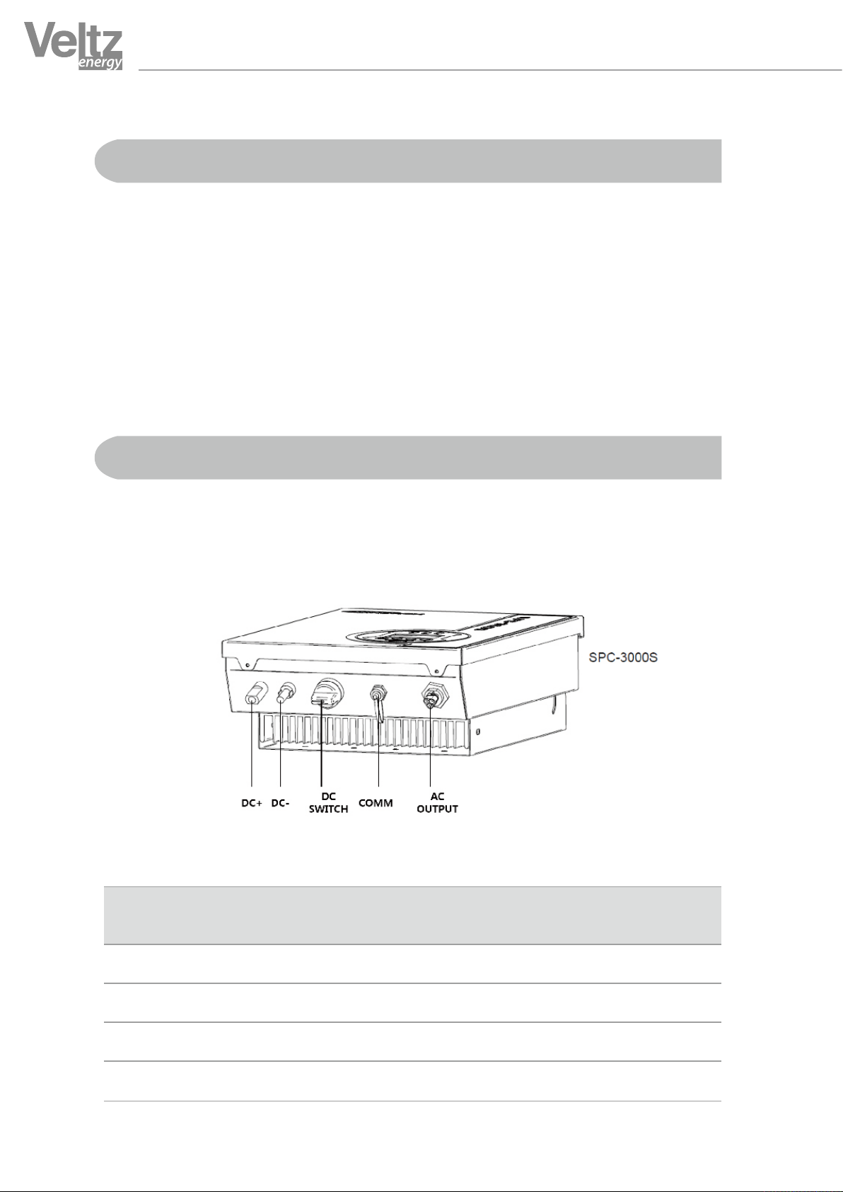
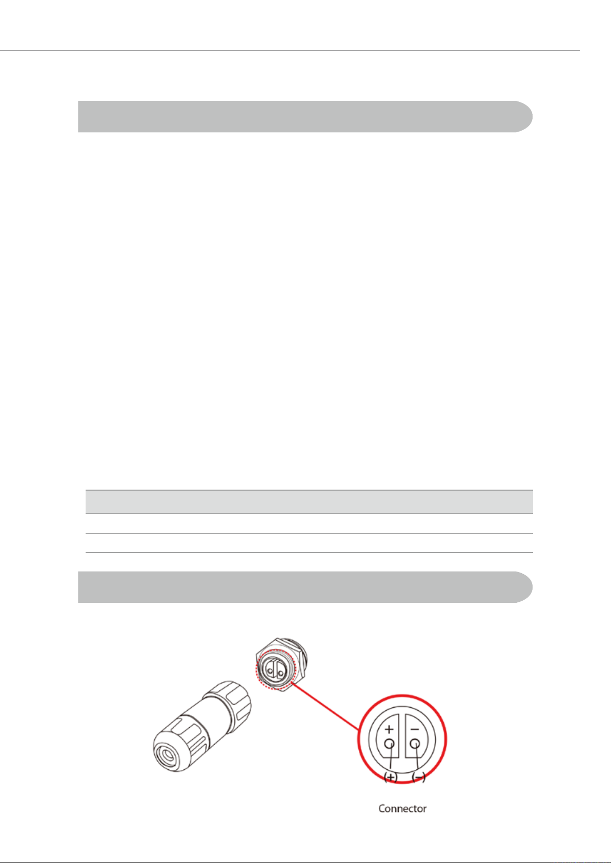
As shown below, connector joints are on the bottom of the inverter. Read the terminal connection
diagram carefully before connecting connectors.
Installation Site
Terminal Connection
Terminal
Symbol Terminal Name
DC + Solar Input Power (+)
Connect it with the positive pole (+) of solar cell powe
Connect it with the negative pole (-) of solar cell power.
Connect the inverter output with KOPEC system and the ground wire.
Connect it with the monitoring system signal line.
DC - Solar Input Power (-)
AC System Power Terminal
RS485 Communication Terminal
Terminal Description
11
www.veltzenergy.com
Veltz Energy Product Instruction Manual
Wiring
Terminal Connection For Monitoring
Precautions when wiring the main circuit
RS485C Communication Terminal and Connector
- Connect the input terminal [+] of the inverter to the (+) connector, and the input terminal [-] of the
inverter to the (-) connector. Be careful to connect the terminals with their respective
connectors or risk burnout due to wrong wiring of the inverter.
- Do not separate the connector from the inverter during operation.
- If wiring should be changed due to occurrence of inappropriate matters, verify that the keypad LCD
is off before wiring. Immediately after power-off, the capacitor in the inverter is still charged with high
voltage. Therefore, it may still be dangerous.
- To prevent electric shock, apply Type 3 Grounding and less than 100Ω grounding resistance to the
inverter. Connect the inverter to its dedicated grounding terminal. Do not use the case or chassis screw
for the grounding terminal.
- Use the dedicated grounding wire. Connect the inverter to a grounding point close to the inverter if
possible. Use grounding wires with dimensions greater than that as shown below and
perform wiring using the shortest wire length as possible.
- Verify the maximum input voltage of the inverter and the output voltage of the solar cell array.
If the output voltage of the solar cell array exceeds the maximum input voltage of the inverter, the
inverter may be at risk for serious damages.
- When wiring the solar cell module, it is necessary to set the output voltage with the consideration of
the temperature coefficient. If the output voltage of the solar cell array is set without considering the
temperature coefficient, depending on the existing air temperature,
input overvoltage or undervoltage to the inverter may occur.
Capacity
1.5~3kW
5kW
Ground Wire Dimension (㎟)
4.0
5.0
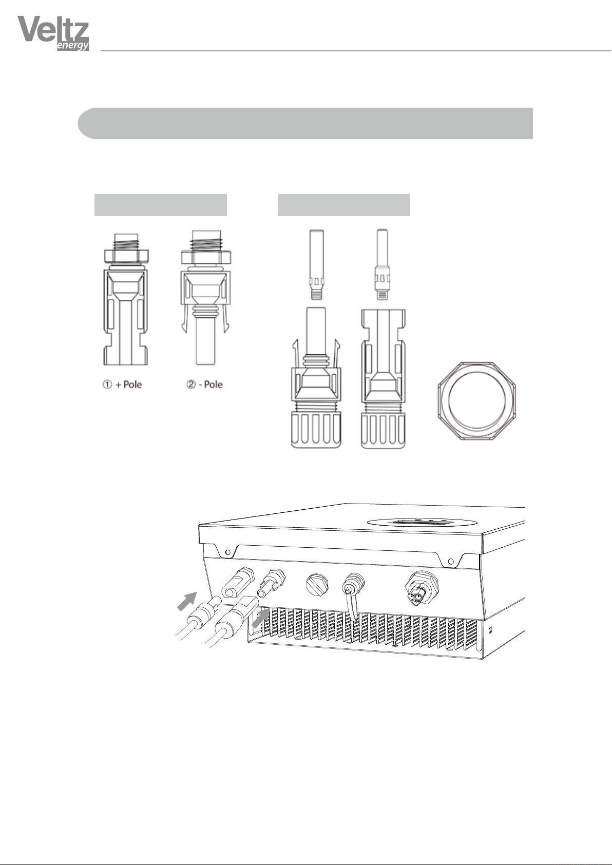
12 Your Smart Energy Solution
DC+ DC- COMM
DC SWITCH
AC OUTPUT
PV INPUT
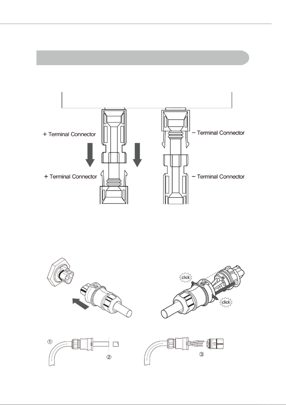
◆ DC Connector Configuration and Installation
◆ How to connect cable terminals and connectors
◆ Terminal connection may be implemented by using terminals and connectors only as shown above.
◆ Caution
- When connecting terminals and connectors, verify that “Click” sound has been made.
Pull both ends to verify that they cannot be separated.
-Before assembling, verify that the terminal is compatible with the connector
①Terminal used to
connect cable and
connector
②Connect with
lower connector as
shown below.
Wiring
Inverter Connector PV Connector
13
www.veltzenergy.com
Veltz Energy Product Instruction Manual
◆ How to connect inverter and connector
◆ How to connect AC connector
* Caution: Connect only with the same electrode as shown : +/+, -/-
Wiring

14 Your Smart Energy Solution
Display
▒ LCD Function
▒ LED BUTTON
▒ LED Function
①
②
②
②
③
③
③
④
④
① Display the current power generation
and the cumulative power generation.
(P: Current Power Generation, E: Cumulative
Power Generation, D: Daily Power Generation)
② Display the input voltage (V) and current (A).
③ Display the output voltage (V), current (A),
and frequency (㎐).
④ Display the power generation by a graph.
① MENU KEY - SETUP - LED Contrast
- Comm Address setting nformation
- Fault Log
- Reset
- Return To Main Display
② UP KEY
③ DOWN KEY
④ ENTER KEY
① POWER: Light up when the power is supplied.
② ALARM: Light up when the inverter is abnormal.
③ RUN: Indicate while the inverter is in operation.
①
①

15
www.veltzenergy.com
Veltz Energy Product Instruction Manual
Operation
▒ Check points before check
▒ Automatic Operation
Verify the wiring and installation status of the inverter.
In particular, verify that the solar cell input polarity is properly connected, including the system line connection.
Supply the solar cell DC power for inverter. When the direct current is supplied,
the inverter will verify the AC power status automatically and will then operate through the
driving countdown process of 300 seconds.
(If necessary, install a DC breaker on the outside of the inverter.)
(By installing the DC breaker, the solar cell power will be supplied to the inverter.)
Whether or not the system voltage is normal is determined by the difference between normal
voltage and abnormal voltage. If the value is smaller or greater than the specified value,
you should stop the inverter. If the system voltage frequency exceeds the specified value,
you should stop the inverter.
To allow the inverter to start power generation in the normal grid status, operate the inverter to the
grid after the completion of the driving countdown process.
The solar cell module output will vary subject to ambient temperature, humidity, and amo unt of sunlight. The
MPPT algorithm should be smoothly implemented. This product has almost no current pulsation. When the
solar cell voltage reaches the stop-voltage level and can no longer drive the inverter,
the inverter will stop. The total generation electricity is cumulatively memorized for you to verify.
When an error occurs that halts the inverter, the inverter will display the relevant messages.
When the cause of error is resolved, the system will begin operation again after the standby time.
If the same problem occurs or the inverter would not function properly, please contact the head office.
When shipped from the factory, the default setting is set to the auto mode.
If the solar cell module voltage rises above the set value (ie: during sunrise), the inverter will automatically
begin operation. At sunset, the solar cell module voltage will fall. If it is less than the set voltage,
the inverter will stop automatically. The system power is always monitored. If there is any abnormality, the
inverter will stop automatically.
◆ System Monitoring
◆ MPPT Control and Total Generation Electricity
◆ Initialization and Emergency Measures
Function

16 Your Smart Energy Solution
Failures and Corrective Actions
Error No. LCD Display System Fault Description Measures
Over Grid Current
Over Temperature
Over Leak Current
Over PV Current
Over PV volt
Error Grid volt
Error Grid
Freq
Insulation
Fault Insulation
3
30
40
4
6
10
8
50
The inverter output Current has
exceed the rated current
The inverter internal temperature
has exceed the rated temperature
Current leakge has occurred
PV array current has exceeded the
rated current
PV array Voltage has exceeded the
rated voltage
The systeme voltage is out of the
specified range
The system frequency is out of the
specified range
The inverter has detected an
earth fault in the PV array.
Wait until the system operates
again in the stop mode.
When re-operation is
not conducted, contact the
after-sales service center.
Wait until the system operates
again in the stop mode.
When re-operation is
not conducted, contact the
after-sales service center.
Identify the PV array
status before operation.
When re-operation is not
conducted, contact the
after-sales service center.
Identify the system power
status before operation.
When re-operation is not
conducted, contact the
after-sales service center.
If any error occurs, this product will display the related messages and automatically stop the operation.
The error message will be displayed on the keypad LCD.
▒ A/S Repair
Identify whether there is any error in the inverter. If there is any fault, you should identify its date, time, and
message. Identify the following prior to inquiring the service center.
1) Model Name
2) Serial No.
3) Purchasing Place
4) Purchasing Year
5) Warranty
6) Fault Matters

17
www.veltzenergy.com
Veltz Energy Product Instruction Manual
memo

18 Your Smart Energy Solution
memo

19
www.veltzenergy.com
Veltz Energy Product Instruction Manual
memo

(Juan-dong) 86, 71beon-gil, Gilpa-ro, Nam-gu, Incheon, Korea
TEL: 82-32-509-5835~7 / 1577-0747
FAX: 82-32-502-5519
A/S Inquiry: 82-32-509-5835
Website: http://www.veltzenergy.com
Table of contents
Popular Inverter manuals by other brands


 Service manual")


Epever
Epever IP350-12 user manual

Fullwat
Fullwat PDA300S user manual

WindTronics
WindTronics AURORA PVI-3.0-OUTD-W quick start guide

Kramer
Kramer TOOLS 810B user manual

Texas Instruments
Texas Instruments TIDM-2014 Design guide

Link electronics
Link electronics Master Analog Generator SPG-812/SD Specification sheet


