Delta Energy Systems RPI H3_110 User manual

Quick Installation Guide
RPI H3_110
United Kingdom Europe
RPI_H3_QIG_V1.0_EU_EN_2015-05-11.indd 1 15.05.15 11:31

2Quick installation guide for RPI H3 inverters
© Copyright – Delta Energy Systems (Germany) GmbH – All
rights reserved.
This manual is included with our solar inverter and is intended for
use by the installer and end user.
The technical instructions and illustrations in this manual are
WREHWUHDWHGDVFRQ¿GHQWLDODQGQRSDUWRIWKLVPDQXDOPD\EH
reproduced without prior written permission from Delta Energy
Systems. Maintenance technicians and end users may not
release the information contained in this manual, and may not
use it for purposes not directly associated with the proper use of
the solar power inverter.
$OOLQIRUPDWLRQDQGVSHFL¿FDWLRQVFDQEHPRGL¿HGZLWKRXWSULRU
notice.
This manual applies for solar inverters models:
ƔRPI H3_110
ZLWK¿UPZDUHYHUVLRQDSP: 2.02 / RED: 2.01 / COMM: 2.05
If you experience deviations between the descriptions in this
quick installation guide and the information on the inverter dis-
play, please check www.solar-inverter.com for a quick installation
JXLGHWKDWPDWFKHVWKH¿UPZDUHYHUVLRQRQWKHLQYHUWHU7KH
standard manual can also be downloaded from www.solar-
inverter.com.
Delta Energy Systems (Germany) GmbH
Tscheulinstrasse 21
79331 Teningen
Germany
Table of contents
1 General safety instructions . . . . . . . . . . . . . . . . . . . . . . . . . . . . . . . . . 3
2 Components of the inverter . . . . . . . . . . . . . . . . . . . . . . . . . . . . . . . . . 4
3 Information on the type label . . . . . . . . . . . . . . . . . . . . . . . . . . . . . . . . 5
4 Scope of delivery . . . . . . . . . . . . . . . . . . . . . . . . . . . . . . . . . . . . . . . 5
5 Planning the installation . . . . . . . . . . . . . . . . . . . . . . . . . . . . . . . . . . . 6
6 Mounting the inverter. . . . . . . . . . . . . . . . . . . . . . . . . . . . . . . . . . . . . 7
7 Connecting to the grid (AC) . . . . . . . . . . . . . . . . . . . . . . . . . . . . . . . . . 8
8 Connecting to the solar modules (DC) . . . . . . . . . . . . . . . . . . . . . . . . . . 10
9 Connecting digital inputs and dry contacts (optional). . . . . . . . . . . . . . . . . . 11
10 Connecting to a datalogger via RS485 . . . . . . . . . . . . . . . . . . . . . . . . . . 12
11 Commissioning - basic settings . . . . . . . . . . . . . . . . . . . . . . . . . . . . . . 14
12 Commissioning - further settings (optional) . . . . . . . . . . . . . . . . . . . . . . . 14
Inverter ID . . . . . . . . . . . . . . . . . . . . . . . . . . . . . . . . . . . . . . . . . . 14
Baud rate. . . . . . . . . . . . . . . . . . . . . . . . . . . . . . . . . . . . . . . . . . . 15
Date and time . . . . . . . . . . . . . . . . . . . . . . . . . . . . . . . . . . . . . . . . 16
Language . . . . . . . . . . . . . . . . . . . . . . . . . . . . . . . . . . . . . . . . . . 17
13 Technicaldata. . . . . . . . . . . . . . . . . . . . . . . . . . . . . . . . . . . . . . . . 18
Service Europe . . . . . . . . . . . . . . . . . . . . . . . . . . . . . . . . . . . . . . . 20
RPI_H3_QIG_V1.0_EU_EN_2015-05-11.indd 2 15.05.15 11:31

3
Quick installation guide for RPI H3 inverters
General Safety Instructions
1
DANGER
Risk of death by electrocution
Potentially fatal voltage is applied to the solar
inverter during operation. This potentially fatal
voltage is still present for 15 seconds after all
power sources have been disconnected.
ŹNever open the solar inverter.
ŹAlways disconnect the solar inverter from
power before installation, open the DC
disconnection switch and make sure neither
can be accidentally reconnected.
ŹWait at least 60 seconds until the capacitors
have discharged.
DANGER
Risk of death or serious injury from elec-
trocution
Potentially fatal voltage may be applied to the
DC connections of the solar inverter. When light
is falling on solar modules, they immediately start
producing energy. They do so, even when the
sun is not shining.
ŹNever disconnect the solar modules when the
solar inverter is powered.
ŹFirst switch off the grid connection so that
the solar inverter cannot feed energy into the
grid.
ŹTurn the DC disconnection switch to position
OFF.
ŹMake sure the DC connections cannot be
accidentally touched.
ƔRead this quick installation guide before you start installing
the inverter.
ƔThe solar inverter can be safely and normally operated if
installed and used in accordance with this manual (see
IEC 62109-5.3.3). Delta Energy Systems is not responsible
for damage incurred by failure to observe the installation and
commissioning instructions in this manual. For this reason,
be sure to observe and follow all instructions!
ƔInstallation and commissioning may only be performed by
TXDOL¿HGHOHFWULFLDQVXVLQJWKHLQVWDOODWLRQDQGFRPPLVVLRQ-
ing instructions found in this manual.
ƔThe solar inverter must be disconnected from power and the
solar modules before any work on it can be performed.
ƔThe solar inverter has a high leakage current value. The
ground wire must be connected before commissioning.
ƔDo not remove any warning signs that the manufacturer has
installed on the solar inverter.
ƔImproper handling of the solar inverter may result in physical
injury and damage to property. For this reason, observe and
follow all general safety instructions and warnings.
ƔThe solar inverter contains no components that must be
maintained or repaired by the operator or installer. All repairs
must be performed by Delta Energy Systems. Opening the
cover will void the warranty.
ƔDo not disconnect any cables when the solar inverter is pow-
ered due to risk of a fault arc.
ƔTo prevent lightning strikes, follow the relevant regulations
applicable in your country.
ƔThe surface of the solar inverter can become very hot dur-
ing operation. Use safety gloves when working on the solar
inverter.
ƔOnly devices in compliance with SELV (EN 69050) may be
connected to the RS485 interfaces.
Ɣ $OOFRQQHFWLRQVPXVWEHVXI¿FLHQWO\LQVXODWHGLQRUGHUWRFRP-
ply with the IP65 protection rating. Unused connections must
be closed by placing cover caps on the solar inverter.
RPI_H3_QIG_V1.0_EU_EN_2015-05-11.indd 3 15.05.15 11:31

4Quick installation guide for RPI H3 inverters
Components of the inverter
2
Label Designation Usage
LEDs
GRID Grid Green; lights up when the solar inverter feeds into the
grid
ALARM Alarm Red; Indicates an error, fault, or warning
Buttons
SEL Select Move to the next menu entry. Change a value. Cancel
value setting.
ENT Enter 6HOHFWPHQXLWHP2SHQFRQ¿JXUDEOHYDOXHIRUHGLWLQJ
Finish editing (adopt set value).
Display, buttons, LEDs
Type label
Electrical connectors
DC switch
DC Inputs
AC Connector
RS485
Digital inputs
and dry contacts
RPI_H3_QIG_V1.0_EU_EN_2015-05-11.indd 4 15.05.15 11:31

5
Quick installation guide for RPI H3 inverters
15 seconds
Risk of death by electrocution
Potentially fatal voltage is present when the solar inverter is in operation that remains for 15 seconds after being
disconnected from power.
Never open the solar inverter. The solar inverter contains no components that must be maintained or repaired by
the operator or installer. Opening the cover will void the warranty.
Read the manual delivered with the inverter before working with the solar inverter and follow the instructions
contained in the manual.
The housing of the inverter must be grounded if this is required by local regulations.
Regulatory Compliance Mark (RCM mark): The inverter is compliant with theAustralian Electrical Safety and
EMC standards. Applies only to Australia and New Zealand.
Information on the type label
3
Scope of delivery
4
AC Plug
Mounting plateInverter
Quick Installation Guide and
General Safety Instructions 2 mounting screws M4 to fasten the
inverter to the mounting plate
Quick Installation Guide
RPI H3_110
Europe
2 x
RPI_H3_QIG_V1.0_EU_EN_2015-05-11.indd 5 15.05.15 11:31

6Quick installation guide for RPI H3 inverters
Planning the installation
5
>30 cm >30 cm >30 cm
>50 cm
>50 cm
ŹEnsure adequate air circulation. Hot air must be able
WRGLVVLSDWHXSZDUG.HHSVXI¿FLHQWVSDFHDURXQG
each inverter.
ŹDo not install inverters directly above one another.
Otherwise, the upper inverter is warmed up by the
lower one.
ŹConsider the operating temperature range (see sec-
tion “Technical Data”).
When the operating temperature range is exceeded,
the solar inverter reduces the amount of power gener-
ated.
Ambient temperature and air circulation
Outdoor installations
ŹThe solar inverter has protection
degree IP65 and can be installed
indoors or in protected outdoor
areas (that means outdoor but
protected by a roof against direct
sun, rain or snow).
ŹMount the solar inverter vertically.
Where to mount the inverter
?
?
?
?
ᅛᅟᅟ
ŹMount the solar inverter so that the
LEDs and display can be easily seen
and that the buttons can be operated.
Make sure the reading angle and instal-
ODWLRQKHLJKWDUHVXI¿FLHQW
ŹAlways use the mounting plate
supplied with the inverter.
ŹCheck that the wall is capable of
bearing the heavy weight of the
inverter.
ŹUse dowels and screws that are
suitable for the wall material and
the heavy weight.
ŹMount the inverter on a vibration-
free wall to avoid disruptive
vibrations.
Ź 0RXQWWKHLQYHUWHURQDÀDWZDOO
only. Brick walls can cause prob-
lems if they are too bumpy.
ŹPossible noise emissions can be
disruptive when the inverter is
used in living areas or in buildings
with animals. Therefore, choose
your installation location carefully.
Mounting orientation
RPI_H3_QIG_V1.0_EU_EN_2015-05-11.indd 6 15.05.15 11:31
7
Quick installation guide for RPI H3 inverters
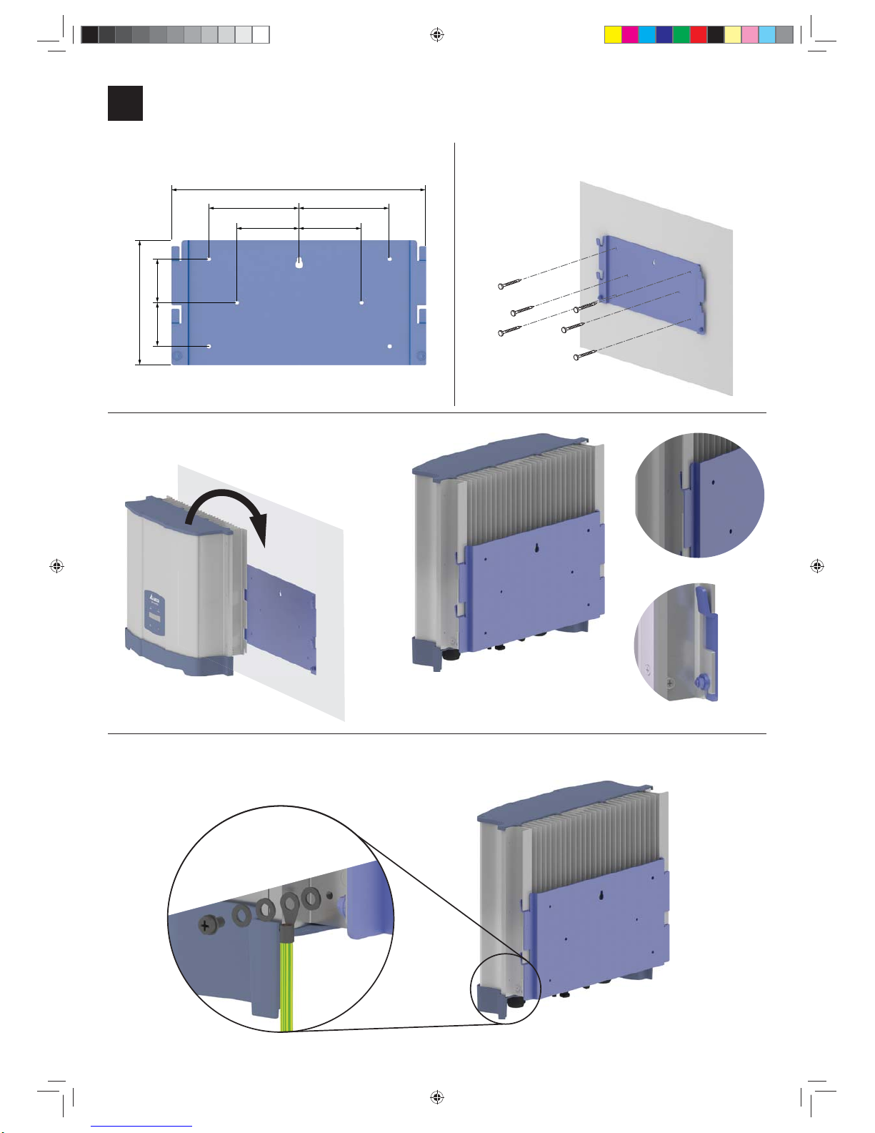
Mounting the inverter
6
392
145 145
200
7070
100100
ŹHang the inverter onto
the mounting plate.
ŹCheck that the rail of the inverter hangs
correctly in the mounting plate and screw
the inverter to the mounting plate.
ŹFasten the mounting plate
with 6 M5 screws to the wall.
12
3
4ŹGround the inverter housing.
Washer spring
Washer
M4 Screw
Grounding cable
Toothed ring
RPI_H3_QIG_V1.0_EU_EN_2015-05-11.indd 7 15.05.15 11:31

8Quick installation guide for RPI H3 inverters
Connecting to the grid (AC)
7
DANGER
Risk of death or serious injury from electrocu-
tion
ŹSet the DC disconnection switch to position OFF
before connecting or disconnecting the AC plug.
AC connector
The AC plug is included in the delivery box
2 = N 1 = L
= PE
Wiring the AC connector: 1 phase (L, N, PE)
Use wire end sleeves on each wire.
12 mm
52.5 mm
12 mm
55 mm (PE)
RPI_H3_QIG_V1.0_EU_EN_2015-05-11.indd 8 15.05.15 11:31

9
Quick installation guide for RPI H3 inverters
$OZD\VDGKHUHWRWKHVSHFL¿FUHJXODWLRQVDSSOLFDEOHLQ\RXUFRXQ-
try or region.
$OZD\VDGKHUHWRWKHVSHFL¿FUHJXODWLRQVGH¿QHGE\\RXUJULG
operator.
For the safety of the user and for the security of your installation,
install safety and protection devices that are required for your
installation environment (example: automatic circuit breaker and/
or overcurrent protection equipment).2
Use the proper upstream circuit breaker to protect the inverter:
Model Upstream Circuit Breaker
RPI H3 16 A
GNL
N
L
PE
to the
inverter
The inverter is not capable of feeding in DC residual currents due
WRLWVGHVLJQ7KH\IXO¿OOWKLVUHTXLUHPHQWLQDFFRUGDQFHZLWK',1
VDE 0100-712.
The possibilities of faults were examined by Delta without tak-
ing the integrated RCMU (residual-current monitoring unit) into
account. When examining these faults in terms of the current
valid installation standards, no danger in combination with a type
A upstream residual-current device (RCD) can occur. Therefore
faults that would otherwise require the use of a type B residual-
current device due to the inverter can be excluded.
The integrated all-pole sensitive RCMU provides additional
safety. RCD Type A can be used for this inverter, according to the
following table.
H3
Minimum tripping current of the RCD 30 mA *
Table: Recommended RCD Type A for one inverter
* see description in the note below
The value of the tripping current mainly depends
on the installation of the PV generator, the size of
the PV array and environmental conditions (e.g.
humidity).
Important information regarding safety AC cable requirements
Use properly sized wires (see table)
AC plug Wieland RST25i3S S1AZR2V
BG03 (96. 032.4154.3)
Current rating $
Min. / max. cable diameter 10 ... 14 mm
Min. / Max. wire diameter 0.75 ... 4 mm2
Recommended torque for termi-
nal screws 0.8 ... 1.0 Nm
Read and follow the instructions delivered with the AC plug.
7KH$&SOXJGHOLYHUHGZLWKWKHLQYHUWHUFDQEHXVHGZLWKÀH[LEOH
or rigid copper cable.
When calculating the cross section of the cable, consider:
Ɣmaterial used
Ɣthermal conditions
Ɣcable length
Ɣtype of installation
ƔAC voltage drop
Ɣpower losses in cable
$OZD\VIROORZWKHV\VWHPLQVWDOODWLRQUHTXLUHPHQWVGH¿QHGIRU
your country!
Grounding the inverter
The inverter must be grounded via the AC connector’s PE con-
ductor. To do this, connect the PE conductor to the designated
terminal of the AC plug.
WARNING
Dual Supply
Do not work on this equipment until it is isolated from
both mains and on site generation supplies
Isolate on-site Generating Unit(s) at ………………………………………………….
Isolate mains supply at………………………………………………………
Warnin
g
–Onl
y
p
ersons authorised b
y
the DNO ma
y
remove the main cut out fuse
Markings on the inverter
In some countries, the following labels have to be applied on the
front of each micro inverter. Please check applicable national and
local standards and regulations.
Warning
Two sources of voltage present
- distribution network
- photovoltaic panels
Isolate both sources before
carrying out any work
RPI_H3_QIG_V1.0_EU_EN_2015-05-11.indd 9 15.05.15 11:31

10 Quick installation guide for RPI H3 inverters
Connecting to the solar modules (DC)
8
It is recommended to use a spe-
cial open-end spanner for the
MC4 DC connectors if you need
to disconnect MC4 DC connectors
from the inverter. Otherwise you
might destroy the DC connectors.
ŹTo ensure protection degree IP65, cap all
unused connectors with the caps delivered
with the inverter.
DC connectors on the inverter Plugs for DC cable
abMultiContact
mm2mm
DC–
^
1,5/2,5 3-6 32.0010P0001-UR
5,5-9 32.0012P0001-UR
4/6 3–6 32.0014P0001-UR
5,5-9 32.0016P0001-UR
DC+ 1,5/2,5 3-6 32.0011P0001-UR
5,5-9 32.0013P0001-UR
4/6 3-6 32.0015P0001-UR
5,5-9 32.0017P0001-UR
a
b
DANGER
Risk of death or serious injury from electrocution
Potentially fatal voltage may be applied to the DC connections of the solar
inverter. When light is falling on solar modules, they immediately start pro-
ducing energy. They do so, even when the sun is not shining directly onto the
solar modules.
ŹTurn the DC disconnection switch to position OFF.
ŹNever disconnect the solar modules when the solar inverter is powered.
ŹFirst switch off the grid connection so that the solar inverter cannot feed
energy into the grid.
ŹMake sure the DC connections cannot be accidentally touched.
'&FDEOHVSHFL¿FDWLRQ
DC Inputs
+
–
DC2
–
+
DC1
ŹCheck the polarity of
the DC voltage before
you connect the solar
modules.
RPI_H3_QIG_V1.0_EU_EN_2015-05-11.indd 10 15.05.15 11:31

11
Quick installation guide for RPI H3 inverters
Connecting digital inputs and dry contacts (optional)
9
When your grid operator wants you to set a power
limitation, e.g. for the 70% regulation in Germany, you
need the Delta Service Software, which is available
from Delta.
If you need to wire dry contacts, digital inputs or RS485,
it is recommended to do this in a dry environment and
before you hang the inverter onto the wall. Reasons for
this are:
ŹYou will have to remove the covers from the
connection ports. Water could leak into the inverter.
ŹThe terminal blocks inside are not easily accessible.
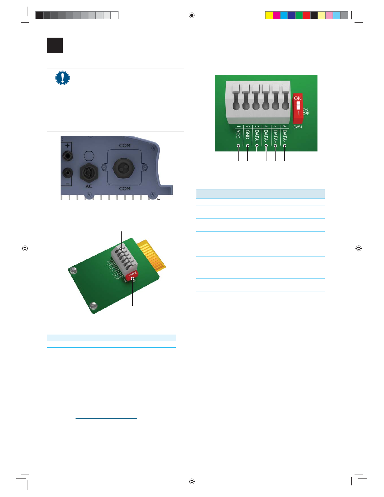
Connector for digital inputs and dry contacts
2
1
Pos. Designation
1 Dry contacts
2 Digital inputs and outputs
Digital inputs
654321
Pin Designation
1 Digital input 1 (DI1)
2 Digital input 2 (DI2)
3 Digital input 3 (DI3)
4 Digital input 4 (DI4)
5 Output 1 (O1)
6 Output 1 (O2)
Dry contacts
When the inverter is feeding into the grid, the dry contact is
closed.
Tips for wiring
ŹUnscrew and carefully pull out the terminal block of the dry
contacts.
ŹUnscrew and carefully pull out the terminal block of the
digital inputs.
RPI_H3_QIG_V1.0_EU_EN_2015-05-11.indd 11 15.05.15 11:31
12 Quick installation guide for RPI H3 inverters
Connecting to a datalogger via RS485
10
If you need to wire dry contacts, digital inputs
or RS485, it is recommended to do this in a dry
environment and before you hang the inverter
onto the wall.
Reasons for this are:
ŹYou will have to remove the covers from the
connection ports. Water could leak into the
inverter.
ŹThe terminal blocks inside are not easily
accessible.
RS485 port
2
1
Connectors on the RS485 card
Pos. Designation
1 RS485 terminal block
2 Switch for RS485 termination resistor
RS485 is used to connect the inverters of the PV plant via a data-
logger to a monitoring system.
VCC can be used for an external relais.
For connecting RS485, Pins 3 to 6 are used.
If you want to use SOLIVIA Monitor, the Internet based monitor-
ing from Delta, you will also need a SOLIVIA M1 G2 Gateway.
Default baud rate is 19200 which can be changed on the inverter
(see chapter “Setting the baud rate”, p. 15).
Pin assignment
214365
RS485 pin assignment
Pin Designation
1VCC
2GND
3 DATA+ (RS485)
4 DATA– (RS485)
5 DATA+ (RS485)
6 DATA– (RS485)
Data format
Baud rate 9600, 19200, 38400;
Standard: 19200
Data bits 8
Stop bit 1
Parity not applicable
RPI_H3_QIG_V1.0_EU_EN_2015-05-11.indd 12 15.05.15 11:31
13
Quick installation guide for RPI H3 inverters
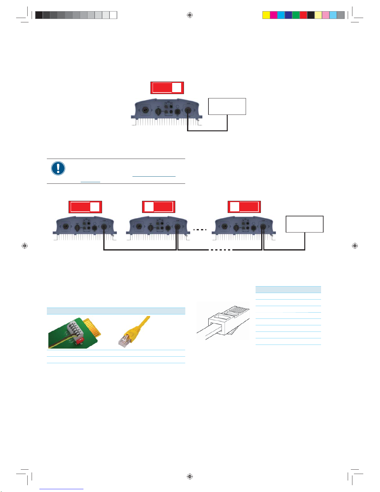
RS485
ONOFF
Datalogger
Termination resistor = ON
Connecting multiple inverters to a datalogger
RS485
ONOFF ONOFF ONOFF
Datalogger
Termination resistor = ON Termination resistor = OFF Termination resistor = OFF
Connecting a single inverter to a datalogger
ŹAls u meerdere omvormers via RS485 aansluit,
moet u een andere omvormer-ID voor elke
omvormer instellen. (zie “Setting the inverter
ID”, p. 14).
On the inverter you connect single wires, on the gateway you
have to use a RJ45 plug.
Connect inverter and gateway according to following table:
Inverter SOLIVIA Gateway M1 G2
Data+ (Terminal 3 or 5) TX_A (Pin 7)
Data- (Terminal 4 or 6) RX_B (Pin 6 or 8)
Connecting the inverter to a SOLIVIA Gateway M1 G2
Pin Assignment
18
1 Reserved
2 Reserved
3 Reserved
4GND
5 Reserved
6 RX_B
7TX_A
8 RX_B
Pin assignment of the RJ45 plug
Connecting to a Delta SOLIVIA Gateway M1 G2
If your datalogger has no integrated termination
resistor, switch on the termination resistor on the
¿UVWLQYHUWHULQWKH56OLQH
RPI_H3_QIG_V1.0_EU_EN_2015-05-11.indd 13 15.05.15 11:31
14 Quick installation guide for RPI H3 inverters
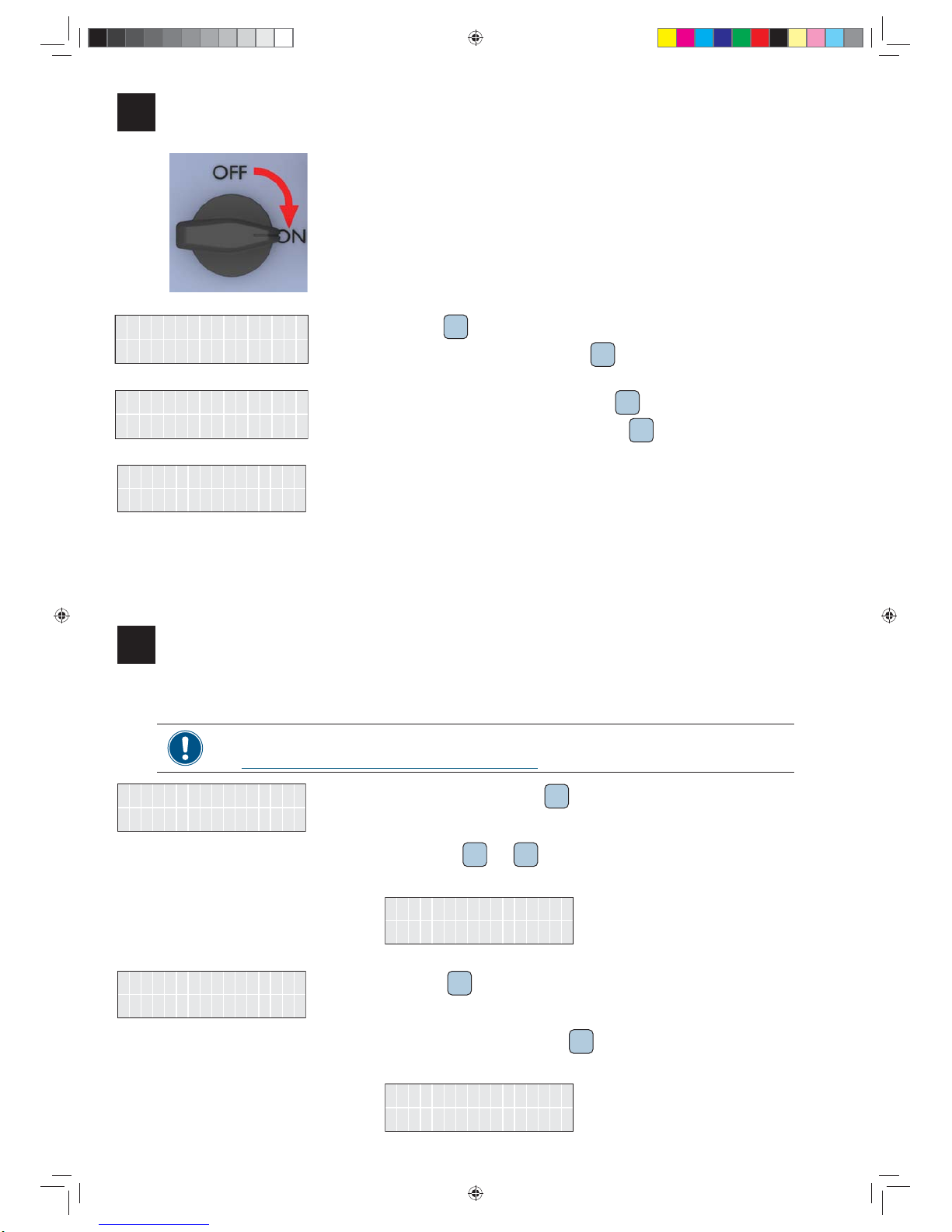
Commissioning - basic settings
11
To execute commissioning, the inverter needs to be pow-
ered either by AC (the grid) or DC (the solar modules)
$IWHUSRZHULQJXSWKHLQYHUWHUIRUWKH¿UVWWLPHWKH
inverter enters the commissioning mode and the Select
language dialog is shown.
Next / Enter
UK G83-2 1. Use the button SEL to select your country or grid.
7RFRQ¿UP\RXUVHOHFWLRQSUHVVWKHEXWWRQ ENT .
N / Y
Exit ? 2. 7R¿QLVKWKHFRXQWU\VHOHFWLRQSUHVVWKHEXWWRQ ENT .
To select another country or grid, press the button SEL and repeat step 1.
;7KHEDVLFVHWXSLV¿QLVKHG7KHPDLQPHQXLVVKRZQ
3.0 kVA
Inverter
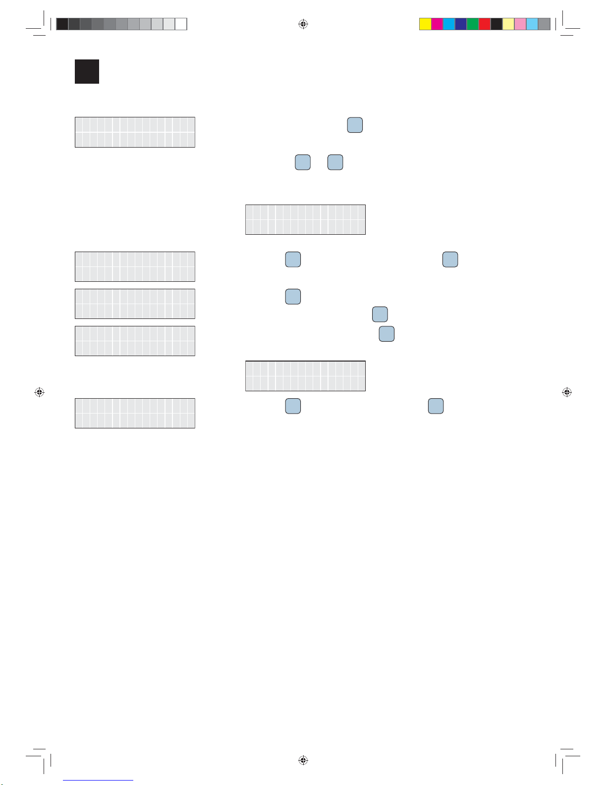
Setting the inverter ID
If your PV plant contains multiple inverters, for each of the inverters a different inverter ID has to be set.
The inverter ID is needed to identify each inverter via RS485. For a description of the RS485 connection,
see “Connecting to a datalogger via RS485 (optional)”, p. 12.
ID : 1
Inverter 1. In the main menu, use the button SEL to select Inverter ID.
2. Press the buttons SEL and ENT at the same time and hold them for at least 3 seconds.
ĺThe menu to change the inverter ID is shown.
ID = 1 ?
Setting ID:
ID = 2 ?
Setting ID: 3. Use the button SEL to change the inverter ID.
4. 7RFRQ¿UPWKHYDOXHSUHVVWKHEXWWRQ ENT .
ĺThe new inverter ID is shown in the main menu.
ID : 2
Inverter
Commissioning - Further settings (optional)
12
RPI_H3_QIG_V1.0_EU_EN_2015-05-11.indd 14 15.05.15 11:31
15
Quick installation guide for RPI H3 inverters
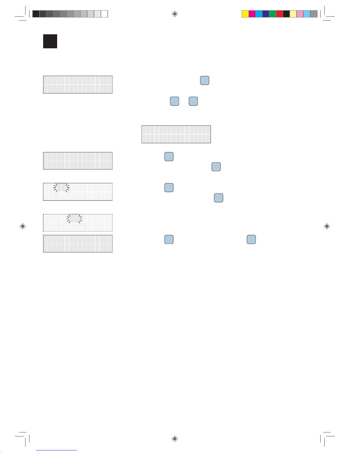
Setting the baud rate
UK G83-2
Country 1. In the main menu, use the button SEL to select Country.
2. Press the buttons SEL and ENT at the same time and hold them for at least 10 sec-
onds.
ĺFor a few seconds the following message is displayed.
Shut down
Inverter
19200
Baud rate 3. Use the button SEL to select Baud rate and press the button ENT .
Next / Enter
9600 4. Use the button SEL to select another baud rate.
To accept the selection, press the button ENT .
N / Y
9600 5. 7RFRQ¿UP\RXUVHOHFWLRQSUHVVWKHEXWWRQ ENT .
ĺThe new baud rate is shown.
9600
Baud rate
N / Y
Exit ? 6. Use the button SEL to select Exit ? and press the button ENT WR¿QLVK
Commissioning - Further settings (continued)
12
RPI_H3_QIG_V1.0_EU_EN_2015-05-11.indd 15 15.05.15 11:31
16 Quick installation guide for RPI H3 inverters
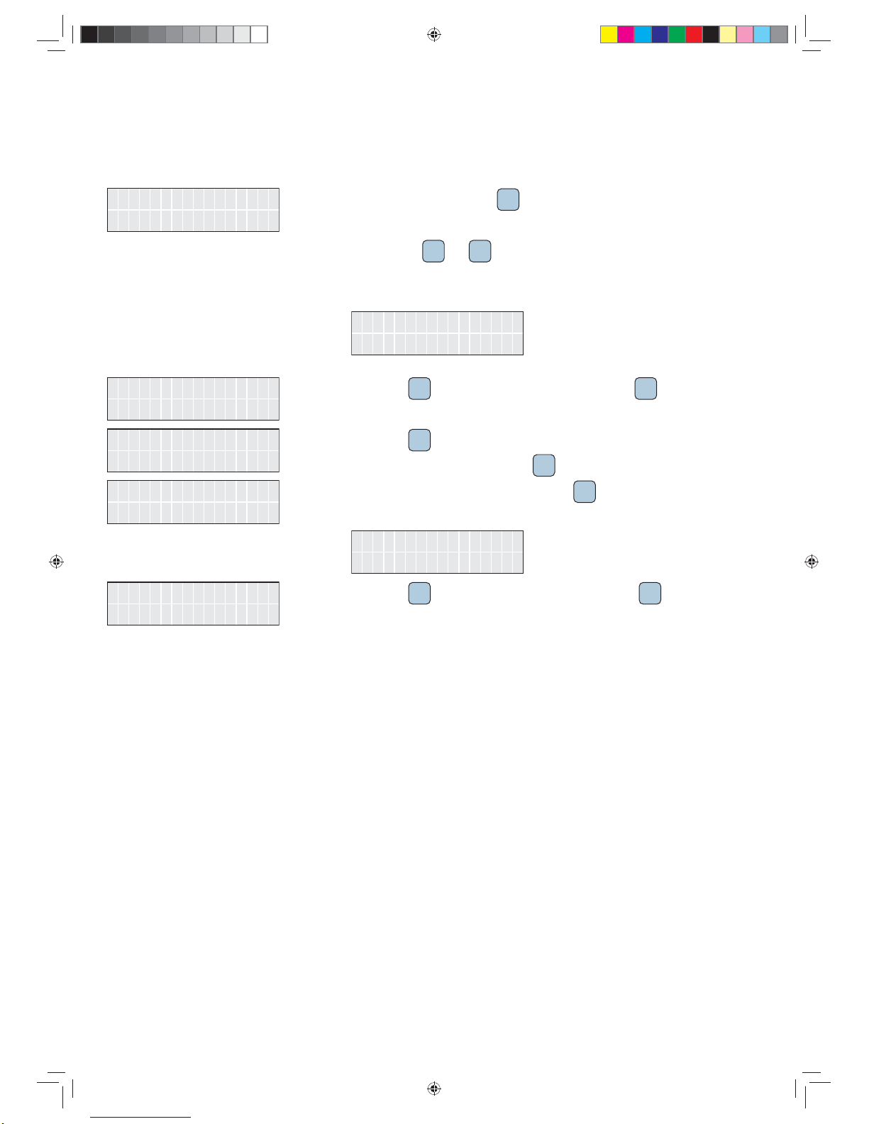
Setting date and time
UK G83-2
Country 1. In the main menu, use the button SEL to select Country.
2. Press the buttons SEL and ENT at the same time and hold them for at least 10 sec-
onds.
ĺFor a few seconds the following message is displayed.
Shut down
Inverter
14:05
26/11/2014 3. Use the button SEL to select the entry with time and date.
To change the setting, press the button ENT .
ĺ 7KHGD\LVÀDVKLQJ
14:05
26/11/2014
/11/2014
14:05
4. Use the button SEL to change the value.
7RFRQ¿UP\RXUVHWWLQJSUHVVWKHEXWWRQ ENT .
ĺ 7KHPRQWKLVÀDVKLQJ
14:05
26/11/2014
26/
/2014
14:05
5. Repeat step 3and 4for each value.
ĺ $IWHUFKDQJLQJWKHYDOXHIRUWKHPLQXWHVWKHÀDVKLQJVWRSV
N / Y
Exit ? 6. Use the button SEL to select Exit ? and press the button ENT WR¿QLVK
Commissioning - Further settings (continued)
12
RPI_H3_QIG_V1.0_EU_EN_2015-05-11.indd 16 15.05.15 11:31
17
Quick installation guide for RPI H3 inverters
Setting the language
UK G83-2
Country 1. In the main menu, use the button SEL to select Country.
2. Press the buttons SEL and ENT at the same time and hold them for at least 10 sec-
onds.
ĺFor a few seconds the following message is displayed.
Shut down
Inverter
English
Language 3. Use the button SEL to select Language and press the button ENT .
Next / Enter
Deutsch 4. Use the button SEL to select another language.
To accept the selection, press the button ENT .
N / Y
Deutsch 5. 7R¿QDOO\FRQ¿UP\RXUVHOHFWLRQSUHVVWKHEXWWRQ ENT .
ĺThe new language is used.
Deutsch
Die Sprache
Nein/Ja
Beenden ? 6. Use the button SEL to select Beenden ? and press the button ENT WR¿QLVK
RPI_H3_QIG_V1.0_EU_EN_2015-05-11.indd 17 15.05.15 11:31

18 Quick installation guide for RPI H3 inverters
Technical data
13
Input (DC) RPI H3
Maximum recommended PV power 3780 WP
Maximum input power 3200 W
Nominal power 3150 W
Voltage range 125 ... 550 VDC
Maximum input voltage 600 VDC 1)
MPP operating voltage range 125 ... 550 VDC
MPP operating voltage range with full power 320 ... 500 VDC
Nominal voltage 350 VDC
Startup voltage 150 VDC
Maximum input current 10 A
Maximum short circuit current in case of a failure 13.9 A
Number of MPP trackers 1
Number of DC inputs 2
Galvanic isolation No
Overvoltage category 2) II
Output (AC) RPI H3
Maximum apparent power 3000 VA
Nominal apparent power 3000 VA
Voltage range 3) 230 V -20%/+22%, 1-phase (L, N, PE or L, L, PE)
Nominal current 13 A
Maximum current 14.3 A
Inrush current 30 A / 1 ms
Maximum output fault current 16 A
Nominal frequency 50 / 60 Hz
Frequency range 3) 50 ± 5 Hz / 60 ± 5 Hz
Power factor adjustable 0.8 cap ... 0.8 ind
Total harmonic distortion <3%
DC current injection <0.25% rated current
Night-time consumption <1 W
Overvoltage category 2) III
1) Can be increased to 630 V
2) IEC 60664-1, IEC 62109-1
3) AC voltage and frequency range will be programmed according to the individual country requirements.
RPI_H3_QIG_V1.0_EU_EN_2015-05-11.indd 18 15.05.15 11:31

19
Quick installation guide for RPI H3 inverters
Mechanical Design RPI H3
Dimensions (W x H x D) 420 x 367 x 157 mm
Weight 15 kg
Cooling Natural convection
AC Connector type Wieland RST25i3S B1G M01
DC Connector type Multi-Contact MC4
Communication interfaces 2 x RS485, 1 x Dry contacts, 4 x Digital inputs
*HQHUDO6SHFL¿FDWLRQ RPI H3
Delta model name RPI H3_110
Delta part number RPI302N63E0000
0D[LPXPHI¿FLHQF\ 97.0%
(8HI¿FLHQF\ 96.2%
Operating temperature range -25 ... +60 °C
Operating temperature range without derating -25 ... +40 °C
Storage temperature range -25 ... +60 °C
Relative humidity 0 ... 95 %, non-condensing
Maximum operating altitude 2000 m above sea level
Standards and Directives RPI H3
Protection degree IP65
Safety class I
Pollution degree II
Overload behavior Current limitation; power limitation
Safety IEC 62109-1 / -2, CE compliance
EMC EN 61000-6-2, EN 61000-6-3
Immunity IEC 61000-4-2 / -3 / -4 / -5 / -6 / -8
Harmonics EN 61000-3-2
9DULDWLRQVDQGÀLFNHU EN 61000-3-3
Grid interfaces See www.solar-inverter.com
RPI_H3_QIG_V1.0_EU_EN_2015-05-11.indd 19 15.05.15 11:31
Service Europe
© Copyright – Delta Energy Systems (Germany) GmbH – All rights reserved.
15.05.2015 - $OOLQIRUPDWLRQDQGVSHFL¿FDWLRQVFDQEHPRGL¿HGZLWKRXWSULRUQRWLFH
5013227800 00
Austria service.oesterreich@solar-inverter.com 0800 291 512 (free call)
Belgium support.belgium@solar-inverter.com 0800 711 35 (free call)
Bulgaria support.bulgaria@solar-inverter.com +421 42 4661 333
Czech Republic podpora.czechia@solar-inverter.com 800 143 047 (free call)
Denmark support.danmark@solar-inverter.com 8025 0986 (free call)
France support.france@solar-inverter.com 0800 919 816 (free call)
Germany service.deutschland@solar-inverter.com 0800 800 9323 (free call)
Greece support.greece@solar-inverter.com +49 7641 455 549
Israel supporto.israel@solar-inverter.com 800 787 920 (free call)
Italy supporto.italia@solar-inverter.com 800 787 920 (free call)
Netherlands ondersteuning.nederland@solar-inverter.com 0800 022 1104 (free call)
Poland support.poland@solar-inverter.com +48 22 335 26 00
Portugal suporte.portugal@solar-inverter.com +49 7641 455 549
Slovakia podpora.slovensko@solar-inverter.com 0800 005 193 (free call)
Slovenia podpora.slovenija@solar-inverter.com +421 42 4661 333
Spain soporto.espana@solar-inverter.com 900 958 300 (free call)
Switzerland support.switzerland@solar-inverter.com 0800 838 173 (free call)
Turkey support.turkey@solar-inverter.com +421 42 4661 333
United Kingdom support.uk@solar-inverter.com 0800 051 4281 (free call)
Other European countries support.europe@solar-inverter.com +49 7641 455 549
RPI_H3_QIG_V1.0_EU_EN_2015-05-11.indd 20 15.05.15 11:31
Table of contents
Other Delta Energy Systems Inverter manuals


Popular Inverter manuals by other brands


Hoymiles
Hoymiles MI-250 Quick installation guide

Analytic Systems
Analytic Systems IPSi1200 Series Installation & operation manual

Goodwe
Goodwe EH Series Quick installation guide

Rigol
Rigol DG1062Z user guide

Growatt
Growatt MOD TL3-XH Series Installation & operation manual

Kaysun
Kaysun KFC-AY-2T-250D owner's manual