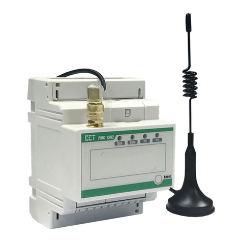
DELTA GROUP EnOcean O3-DIN User guide

O3-DIN
EnOcean Gateway
Application Guide
Firmware 4.11
Edition 2.0

O3-DIN EnOcean Gateway Application Guide Page 2 of 35
Document Edition 2.0
© 2021 Delta Controls Inc. All rights reserved.
No part of this document may be reproduced, transmitted, transcribed, stored in a retrieval
system, or translated into any language (natural or computer), in any form or by any means,
without the prior written permission of Delta Controls Inc.
Limited permission is granted to reproduce documents released in Adobe®Portable Document
Format (PDF) electronic format in paper format. Documents released in PDF electronic format
may be printed by end-users for their own use using a printer such as an inkjet or laser device.
Authorized distributors of Delta Controls Inc. products (Delta Partners) may print PDF
documents for their own internal use or for use by their customers. Authorized Delta Partners
may engage a printing or copying company to produce copies of released PDF documents with
the prior written permission of Delta Controls Inc.
Information in this document is subject to change without notice and does not represent a
commitment to past versions of this document on the part of Delta Controls Inc. Delta Controls
Inc. may make improvements and/or changes to this document/the associated software/or
associated hardware at any time.
BACstat, Earthright, enteliBRIDGE, enteliBUS, enteliCLOUD, enteliSTAT, enteliTOUCH,
enteliVIZ, enteliWEB, enteliZONE, ORCAview, and ORCAweb are registered trademarks of Delta
Controls Inc.
EnOcean®, EnOcean Alliance logo, EnOcean Alliance member logo and EnOcean Alliance
technology logo are registered trademarks of EnOcean GmbH and EnOcean Alliance Inc.
All other trademarks are the property of their respective owners.
Document edition 2.0
January 2021

Page 3 of 35 O3-DIN Gateway Application Guide
Document Edition 2.0
Contents
About This Document .................................................................................................................5
Document Conventions .............................................................................................................. 5
Related Documents.................................................................................................................... 5
Introduction................................................................................................................................6
EnOcean Basics.......................................................................................................................... 6
O3-DIN EnOcean Gateway Basics .............................................................................................. 6
O3-DIN EnOcean Gateway Specifications .................................................................................. 7
Getting Started ...........................................................................................................................8
Setting Up an EnOcean Network................................................................................................ 8
Setting Up the O3-DIN EnOcean Gateway.................................................................................. 9
Configuring Input Devices ........................................................................................................10
Configuring Input Devices Using a Sensor Hub ........................................................................10
Configuring Input Devices Using a CON-ENOC ........................................................................11
Manually Pairing an EnOcean Device........................................................................................12
Resetting Pairing.......................................................................................................................12
Configuring Output Devices......................................................................................................13
Main Steps for Configuring Output Devices..............................................................................13
Configuring Simple Relays........................................................................................................14
Configuring Load Controllers with Central Command Support ...............................................18
Configuring Radiator Valve Controllers....................................................................................20
Monitoring Network Communication .......................................................................................22
Understanding the Link Status .................................................................................................22
Understanding the Reliability Timer .........................................................................................23
Monitoring Communication Statistics.......................................................................................23
Working with Range and Scale Values .....................................................................................24
Understanding Range and Scale Values...................................................................................24
Using a BV Object to Show Off/On States..................................................................................25

O3-DIN EnOcean Gateway Application Guide Page 4 of 35
Document Edition 2.0
Working with Mapping Files .....................................................................................................26
Modifying a Default Mapping File..............................................................................................26
Creating a Custom XML Mapping File.......................................................................................28
Saving Mapping Data.................................................................................................................29
Appendix A: Troubleshooting ...................................................................................................30
Troubleshooting a Sensor Hub .................................................................................................30
Troubleshooting a CON-ENOC..................................................................................................31
Troubleshooting EnOcean Objects............................................................................................32
Appendix B: Supported FIL EEP Profiles..................................................................................33
Document Revision History ......................................................................................................35

Page 5 of 35 O3-DIN Gateway Application Guide
Document Edition 2.0
About This Document
This document describes how to connect EnOcean®devices to a BACnet network using the
O3-DIN EnOcean gateway.
The information in this document applies to O3 firmware version 4.11 and enteliWEB 4.17.
Document Conventions
Symbols
Indicates important information to the user.
Indicates an action that could potentially result in damage to
equipment or loss of data.
Terminology
Whenever the term "sensor hub" or "hub" is used in this document, it refers to the O3-HUB and
its variants. It never refers to the O3 Sensor Hub 2.0 (O3-HUB2), which is not compatible with
the O3-DIN EnOcean Gateway.
Related Documents
For additional information, refer to the following documents on support.deltacontrols.com
(requires a Passport account):
•O3-DIN-CPU Installation Guide
•O3-DIN-SRC Installation Guide
•O3-HUB Installation Guide
•CON-ENOC Installation Guide
•enteliWEB 4.17 Help
•Delta Controls Wiring Guidelines

O3-DIN EnOcean Gateway Application Guide Page 6 of 35
Document Edition 2.0
Introduction
This section covers the following topics:
•EnOcean Basics
•O3-DIN EnOcean Gateway Basics
•O3-DIN EnOcean Gateway Specifications
EnOcean Basics
EnOcean is a wireless protocol for ultra-low power energy harvesting sensors, switches, and
controls. EnOcean devices offer batteryless, maintenance-free operation and come with
standardized communication profiles to ensure interoperability across manufacturers.
EnOcean devices use short, infrequent radio signals and can transmit over distances of up to
30 m (100 ft) indoors. The signals are received and processed by line-powered devices such as
relay switch actuators, repeaters, or gateways.
For more information about the EnOcean wireless standard, see https://www.enocean.com and
https://www.enocean-alliance.org
O3-DIN EnOcean Gateway Basics
The O3-DIN EnOcean gateway connects wireless EnOcean devices to the BACnet building
network using a wired serial connection to an EnOcean-capable O3-HUB sensor hub or
CON-ENOC adapter. The communication protocol is defined by EnOcean Serial Protocol 3.0.
The gateway acts as both a receiver and a transmitter, reading EnOcean input devices and
writing to EnOcean output devices. Interactions with EnOcean devices are represented using
BACnet objects.
The gateway uses Structured View (SV) objects to represent EnOcean devices on the network.
The device SV object maps data from the device based on an XML mapping file. Normally, this is
a predefined EnOcean Equipment Profile (EEP) but custom mapping files are also supported.
The gateway currently supports the following EEP types:
•F6: Repeated Switch Communication (RPS) Telegram e.g., F6-02-01
•D5: 1 Byte Communication (1BS) Telegram e.g., D5-00
•A5: 4 Byte Communication (4BS) Telegram e.g., A5-20-01
For more information, see http://tools.enocean-alliance.org/EEPViewer.
Communication is established between the gateway and an EnOcean device through a pairing
process in which the device is put into learn mode and a "learn in" or "learn out" packet is sent
from the gateway to the device.

Page 7 of 35 O3-DIN Gateway Application Guide
Document Edition 2.0
O3-DIN EnOcean Gateway Specifications
The following table lists the specifications of the EnOcean gateway in O3 firmware version 4.11:
Gateway Capacity
•Up to 32 devices per EnOcean radio with device numbers in
the range 01–32. Device SV instances in the 33–99 range
are not supported.
•
Up to 8 O3-HUB-En
xxx
sensor hubs connected to an
O3-DIN-CPU controller
or
up to 2 O3-HUB-En
xxx
sensor
hubs connected to an O3-DIN-SRC controller
or
1
CON-ENOC connected to either O3-DIN controller.
•
Up 32 EnOcean devices per O3-HUB-En
xxx
sensor hub or
CON-ENOC. With 8 sensor hubs, a total of 256 EnOcean
devices are possible.
•
Recommend less than 13 points per EnOcean device.
EnOcean Data Units
Frame packet (physical layer), subtelegram (data link layer),
t
elegram (network layer).
EnOcean Equipment Profiles
27 FIL object EEPs are included in the firmware.
BACnet Objects
Analog Value, Binary Value, Character String Value
Auto Mapping/Discovery
•Supports auto learn feature for inputs
•
Supports one click learn out, three click learn out, custom
4BS, and 4BS Variant 3 learn out for outputs
•
Allows manual addressing
Supported EnOcean Devices
•868 MHz (Europe) or 902 MHz (North America) EnOcean
input (read) devices
•
868 MHz (Europe) or 902 MHz (North America) EnOcean
output (write) devices
EnOcean Communication
Protocol
Supports ESP3 (EnOcean Serial Protocol 3.0). Does not support
older ESP version
s (e.g., ESP2).
Communication
•CANbus (O3BUS) using the NET3 port (O3-HUB-En
xxx
)
•
RS-485 serial at 38400 baud over NET1/2/3 (CON-ENOC)

O3-DIN EnOcean Gateway Application Guide Page 8 of 35
Document Edition 2.0
Getting Started
This section covers the following topics:
•Setting Up an EnOcean Network
•Setting Up the O3-DIN EnOcean Gateway
Setting Up an EnOcean Network
Before installing EnOcean devices, conduct a site survey to assess optimal placement of
sensors and receivers.
To conduct a site survey:
1. Obtain a floor plan of the space.
2. Mark the locations of fire protection walls, staircases, elevator shafts, restrooms, server
rooms, and any other areas of the building that may block radio signals.
3. Using a compass, draw a circle around each proposed receiver location (where you plan
to install an O3-HUB-En
xxx
sensor hub or CON-ENOC device). The circle represents the
effective radio signal range. Each circle should cover approximately 20 m (66 ft) and
overlap as little as possible with other circles.
EnOcean sensors should be located within a 10 m (33 ft) radius of the receiver. Ideally, the
wireless signal should have an unobstructed line-of-sight path to the receiver. It should not
cross any of the marked areas. For more details, see https://www.enocean.com/en/support.
As sensors are installed, conduct field tests with a handheld radio signal strength meter at each
receiver location and verify that the signal is properly received. In some cases, you may need to
move the sensors, change antenna positions, or add repeaters to achieve the desired result. As
each receiver location is verified, record the signal strength measurements on the floor plan.

Page 9 of 35 O3-DIN Gateway Application Guide
Document Edition 2.0
Setting Up the O3-DIN EnOcean Gateway
The O3-DIN EnOcean Gateway requires a controller and an EnOcean receiver. The controller
can be an O3-DIN-CPU or an O3-DIN-SRC. The receiver can be an EnOcean-capable O3-HUB
sensor hub (e.g., O3-HUB-En902) or a CON-ENOC adapter.
Sensor hubs communicate with O3-DIN controllers over an O3BUS (CAN-based) network.
CON-ENOCs communicate with O3-DIN controllers over an RS-485 connection at 38400 bps.
The O3-DIN-CPU controller can support up to 8 sensor hubs or 1 CON-ENOC. The O3-DIN-SRC
controller can support up to 2 sensor hubs or 1 CON-ENOC. You cannot use sensor hubs and
CON-ENOCs together.
To set up an O3-DIN EnOcean Gateway with one or more sensor hubs:
1. Shut off power to the controller.
2. Connect the sensor hub’s O3BUS port to the controller’s NET3 port.
3. Connect the sensor hub’s PWR input to PWR OUT 1 on an O3-DIN-CPU controller or to
an external 24 VDC power supply.
4. If you are connecting only one sensor hub to the O3BUS network, leave the device
address as the default setting (2). If you are connecting more than one sensor hub, wire
the hubs in a daisy chain and set each hub to a unique address between 2 and 9. The
total length of the O3BUS network must not exceed 70 m (230 ft).
5. The O3BUS network must be terminated at both ends. Sensor hubs and the latest
O3-DIN controllers have a built-in termination switch. Set the switch to TERM on the
device at each end of the daisy chain. (Older O3-DIN controllers need a 120 Ω
termination resistor across the NET3 port pins for termination.)
6. Turn on power to the controller and sensor hub(s). If a sensor hub is being powered by
the controller (that is, it is connected to PWR OUT 1 on an O3-DIN-CPU), in enteliWEB,
command the BO1 object on the controller to On.
To set up an O3-DIN EnOcean Gateway with a CON-ENOC, connect the CON-ENOC to the
controller’s RS-485 port (NET1, NET2, or NET3 on an O3-DIN-CPU; NET1 on an O3-DIN-SRC).
For more information, refer to the product installation guides on support.deltacontrols.com.

O3-DIN EnOcean Gateway Application Guide Page 10 of 35
Document Edition 2.0
Configuring Input Devices
This section covers the following topics:
•Configuring Input Devices Using a Sensor Hub
•Configuring Input Devices Using a CON-ENOC
•Manually Pairing an EnOcean Device
•Resetting Pairing
Configuring Input Devices Using a Sensor Hub
To configure EnOcean input devices using a sensor hub:
1. In enteliWEB, open the NP3 object on the controller, set the Protocol Type to CANbus,
save the change, then activate the change (Device Actions > Activate Network Change).
2. Create object BV30s030 ("Enable EnOcean") to enable the EnOcean radio in the sensor
hub, replacing swith the sensor hub's rotary switch address (2–9), then command the
object to On. If you are using multiple hubs, create this BV object for each hub.
3. To verify that EnOcean is enabled, open the controller’s IOM object. You should see a
new virtual port representing the EnOcean network hosted by the sensor hub. For
example, 3200000.
4. Create an SV object for the EnOcean network. The object instance follows the format
3s00000, where sis the sensor hub address. For example, if the sensor hub address is 2,
create SV3200000. If the sensor hub address is 9, create SV3900000. If you are using
multiple hubs, create a network SV object for each hub.
5. Create an SV object for each EnOcean device (up to 32 per sensor hub). The object
instance follows the format 3sDD000, where sis the sensor hub address and DD is the
device number in the range 01 to 32. For example, if the sensor hub address is 2 and the
device number is 01, create SV3201000.
6. Associate a mapping file with each device SV object.
a. Open the device SV object.
b. In Gateway Mapping, select the FIL object that contains the desired EnOcean
Equipment Profile (EEP) or other XML mapping.
c. Click Save. The Subordinates section populates with a list of suggested BACnet
object instances and names.
7. Create BACnet objects for each EnOcean device.
a. Using the instances and names shown in the Subordinates section of the device
SV object, create the objects needed for your application. At a minimum, create

Page 11 of 35 O3-DIN Gateway Application Guide
Document Edition 2.0
the Learn Mode BV, Link Status CSV, and Device Address CSV objects. The Device
Address CSV object instance follows the format 3sDD999, where sis the sensor
hub address and DD is the device number in the range 01 to 32. For example, if
the sensor hub address is 2 and the device number is 01, create CSV3201999.
b. Verify that the created objects show as blue hyperlinks in the Subordinates
section of the device SV object (clicking the link opens the object page).
8. Pair each EnOcean device to its device SV object.
a. Command the Learn Mode BV object to On. The Link Status CSV object changes
to "Pairing."
b. If the EnOcean device has a Learn button, press the button to start pairing. When
pairing is complete, the Device Address CSV object shows the device’s ID and the
Link Status CSV object changes to "Online." If the EnOcean device does not have
a Learn button (for example, a rocker switch), activate the device (press the
rocker switch) to allow the gateway to learn the device ID. This should initiate
pairing.
c. Once the pairing is complete, command the Learn Mode BV object to Off.
If a FIL object associated with a Device SV object is changed or edited, a controller reboot is
required to clear data from the previous profile.
Configuring Input Devices Using a CON-ENOC
To configure EnOcean input devices using a CON-ENOC adapter:
1. In enteliWEB, open the NP object on the controller that corresponds to the physical NET
port that the CON-ENOC is connected to. Set the Protocol Type to EnOcean, save the
change, then activate the change (Device Actions > Activate Network Change).
2. Create an SV object for the EnOcean network. The object instance follows the format
p00000, where pis the number of the NET port (1–3) that the CON-ENOC is connected to.
For example, if the CON-ENOC is connected to NET1, create SV100000.
3. Create an SV object for each EnOcean device (up to 32). The object instance follows the
format pDD000, where pis the number of the NET port that the CON-ENOC is connected
to, and DD is the device number in the range 01 to 32. For example, if the NET port
number is 1 and the device number is 01, create SV101000.
4. Associate a mapping file with each device SV object.
a. Open the device SV object.
b. In Gateway Mapping, select the FIL object that contains the desired EnOcean
Equipment Profile (EEP) or other XML mapping.
c. Click Save. The Subordinates section populates with a list of suggested BACnet
object instances and names.

O3-DIN EnOcean Gateway Application Guide Page 12 of 35
Document Edition 2.0
5. Create BACnet objects for each EnOcean device.
a. Using the instances and names shown in the Subordinates section of the device
SV object, create the objects needed for your application. At a minimum, create
the Learn Mode BV, Link Status CSV, and Device Address CSV objects. The Device
Address CSV object instance follows the format pDD999, where pis the number
of the NET port that the CON-ENOC is connected to, and DD is the device number
in the range 01 to 32. For example, if the NET port number is 1 and the device
number is 01, create CSV101999.
b. Verify that the created objects show as blue hyperlinks in the Subordinates
section of the device SV object (clicking the link opens the object page).
6. Pair each EnOcean device to its device SV object.
a. Command the Learn Mode BV object to On. The Link Status CSV object changes
to "Pairing."
b. If the EnOcean device has a Learn button, press the button to start pairing. When
pairing is complete, the Device Address CSV object shows the device’s ID and the
Link Status CSV object changes to "Online." If the EnOcean device does not have
a Learn button (for example, a rocker switch), activate the device (press the
rocker switch) to allow the gateway to learn the device ID. This should initiate
pairing.
c. Once the pairing is complete, command the Learn Mode BV object to Off.
If a FIL object associated with a Device SV object is changed or edited, a controller reboot is
required to clear data from the previous profile.
Manually Pairing an EnOcean Device
If you already know the address of the EnOcean device you want to link to, you can simply open
the Device Address CSV object and manually enter the hexadecimal address as the object value.
Resetting Pairing
To prevent re-pairing the same device, EnOcean learn packets received when the Device
Address CSV has a non-zero value are ignored. If the EnOcean device you want to link to was
previously paired to another device, manually set the Device Address CSV object to 0, then put it
back in Auto mode. The device is now ready to pair.

Page 13 of 35 O3-DIN Gateway Application Guide
Document Edition 2.0
Configuring Output Devices
This section covers the following topics:
•Main Steps for Configuring Output Devices
•Configuring Simple Relays
•Configuring Load Controllers with Central Command Support
•Configuring Radiator Valve Controllers
Main Steps for Configuring Output Devices
The steps for configuring an EnOcean output device are essentially the same as for configuring
an EnOcean input device:
1. Set up the network port for EnOcean communication.
2. If you are using sensor hubs, create a BV30s030 object for each hub (where sis the hub
address in the range 2 to 9) to enable its EnOcean radio, and command the object to On.
3. Create the network and device SV objects.
4. Associate a mapping file with each device SV object.
5. Create the BACnet objects needed for your application, either manually or using the
Database Creation tool.
6. Pair each EnOcean device to its device SV object. The EnOcean output device is put into
learn mode and a learn out packet is sent from the gateway to the device.
For detailed instructions regarding steps 1 to 4, refer to the previous section, Configuring Input
Devices. The remainder of this section will focus on steps 5 and 6.

O3-DIN EnOcean Gateway Application Guide Page 14 of 35
Document Edition 2.0
Configuring Simple Relays
Simple relays provide basic on/off control and do not offer any feedback.
The mapping file should contain the following objects:
Name
Reference (Sensor Hub)
Reference (CON-ENOC)
Device Type AV3sDD993 (e.g., AV3201993) AVpDD993 (e.g., AV101993)
OFF Value AV3sDD990 AVpDD990
ON Value AV3sDD991 AVpDD991
Relay ONOFF BV3sDD001 BVpDD001
s= hub rotary switch address (2–9) p= controller NET port (1–3) DD = EnOcean device number (01–32)
The Device Type AV object is used for output control and defines two categories of devices: 0 =
Input and output with feedback, and 1 = Output only. For a simple relay, the Device Type value is
set to 1.
Depending on the vendor, required on and off levels may vary. The OFF Value and ON Value AV
objects provide a flexible way to configure these values. These objects define the packet data
value being sent out to command something on or off.
The following procedure assumes that you have already completed steps 1 to 4 in Main Steps
for Configuring Output Devices.
To configure a simple relay:
1. Create the Device Type AV object and set the value to 1 to define an output without
feedback.
2. Create the OFF Value AV object and set the value. For example, 112(0x70H).
3. Create the ON Value AV object and set the value. For example, 80(0x50H).
4. Create the Relay ONOFF BV object defined in the mapping file.
5. Create any other objects needed for your application.
6. Ensure that all Learn Out BV objects are Off.
7. Put the relay into learn mode. For specific instructions, consult the manufacturer's
documentation.
8. Command the Learn Out BV object you are using (One Click Learn Out or Three Click
Learn Out) to On.
9. After the relay has paired with the gateway, command the Learn Out BV object to Off.
10. Verify that the Relay ONOFF BV object controls the relay state.

Page 15 of 35 O3-DIN Gateway Application Guide
Document Edition 2.0
RPS Force Send
Since simple relays do not include a feedback function, there is no indication of the relay's
actual state. In some cases, you may want to send the same command again to ensure that the
command was received and acted on correctly by the relay output device.
The RPS Force Send BV object (BV3sDD982 or BVpDD982) provides a way to send the current
relay output value even if that value has not changed.
Note: RPS is an EnOcean term that refers to the repeated switch communication telegram type.
EEPs that use RPS telegrams start with F6. For example, F6-02-01.
To use the RPS Force Send feature:
1. Verify that the OFF Value AV and ON Value AV objects are set to the required values.
2. Command the RPS Force Send BV object to On. This sends the current value of the Relay
ONOFF Output BV object.
To use Force Send repeatedly, the Force Send BV object must be toggled ON and OFF at a rate
slower than the program scan rate. Here are some sample programs that can help ensure that
the ON/OFF signals are sent at the correct intervals.
The following pseudo code shows the idea of a state machine:
Variable Run As Integer
Variable Time As Real
<other parts of the GCL, which sets "Run" and "Time">
If (Run =0) Then
If ( State > 1 ) Then
BV = 0
State = 0
End If
Else
DoEvery ( Time )
State = State + 1
If (State = 1) Then
BV = 1
Else
BV = 0
State = 0
End If
End Do
End If
<the rest of the GCL+ program>
In the preceding code, "Run" is a GCL+ integer variable that indicates that RPS Force Send
should be set periodically when it is non-zero. "Time" is a GCL+ variable that indicates the value
of the desired RPS Force Send interval. "State" represents the AV object that retains its value
between scans. "BV" represents the RPS Force Send BV object.

O3-DIN EnOcean Gateway Application Guide Page 16 of 35
Document Edition 2.0
You will need to create the following additional objects:
Name
Referenc
e
Description
PG1 PG1 Master program to call PG2 and PG3
PG2 PG2 Program to send ON followed by Release
PG3 PG3 Program to send OFF followed by Release
Rocker ON and
release switch
BV1 For PG2
Rocker OFF and
release switch
BV2 For PG3
Rocker ON state variable AV1 For PG2
Rocker OFF state variable AV2 For PG3
PG1Code: Calls the Two Programs
Call PG2
Call PG3
PG2 Example Code: Sends the ON Followed by a Release Packet
Variable ON_VALUE As Integer
Variable RELEASE_VALUE As Integer
ON_VALUE = 80
RELEASE_VALUE = 0
If ('Rocker ON and release switch' = 0) Then
If ('Rocker ON state variable' > 7) Then
'RPS Force Send' = Off
'Rocker ON state variable' = 0
End If
Else
DoEvery 0.1S
'Rocker ON state variable' = 'Rocker ON state variable' + 1
If ('Rocker ON state variable' = 1) Then
'ON Value' = ON_VALUE
'RPS Force Send' = Off
ElseIf ('Rocker ON state variable' = 2) Then
// send the ON packet here
If ('RPS Send .Manual_Override' = Off) Then
'RPS Send .Manual_Override' = On
Else
'RPS Force Send' = On
End If
ElseIf ('Rocker ON state variable' = 3) Then
'RPS Force Send' = Off
ElseIf ('Rocker ON state variable' = 4) Then
'ON Value' = RELEASE_VALUE
ElseIf ('Rocker ON state variable' = 5) Then
// send the release packet here

Page 17 of 35 O3-DIN Gateway Application Guide
Document Edition 2.0
'RPS Force Send' = On
ElseIf ('Rocker ON state variable' = 6) Then
'RPS Force Send' = Off
Else
'ON Value' = ON_VALUE
'Rocker ON state variable' = 0
'Rocker ON and release switch.Manual_Override' = 0
End If
End Do
End If
PG3 Example Code: Sends the OFF Followed by a Release Packet
Variable OFF_VALUE As Integer
Variable RELEASE_VALUE As Integer
OFF_VALUE = 112
RELEASE_VALUE = 0
If ('Rocker OFF and release switch' = 0) Then
If ('Rocker OFF state variable' > 7) Then
'RPS Force Send' = Off
'Rocker OFF state variable' = 0
End If
Else
DoEvery 0.1S
'Rocker OFF state variable' = 'Rocker OFF state variable' + 1
If ('Rocker OFF state variable' = 1) Then
'OFF Value' = OFF_VALUE
'RPS Force Send' = Off
ElseIf ('Rocker OFF state variable' = 2) Then
// send the ON packet here
If ('RPS Send .Manual_Override' = On) Then
'RPS Send .Manual_Override' = Off
Else
'RPS Force Send' = On
End If
ElseIf ('Rocker OFF state variable' = 3) Then
'RPS Force Send' = Off
ElseIf ('Rocker OFF state variable' = 4) Then
'OFF Value' = RELEASE_VALUE
ElseIf ('Rocker OFF state variable' = 5) Then
// send the release packet here
'RPS Force Send' = On
ElseIf ('Rocker OFF state variable' = 6) Then
'RPS Force Send' = Off
Else
'OFF Value' = OFF_VALUE
'Rocker OFF state variable' = 0
'Rocker OFF and release switch.Manual_Override' = 0
End If
End Do
End If

O3-DIN EnOcean Gateway Application Guide Page 18 of 35
Document Edition 2.0
Configuring Load Controllers with Central Command Support
Load controllers are typically used in lighting and HVAC circuit applications and usually include
a feedback signal.
Many EnOcean output devices offer central command support (A5-38-08). This feature is
typically used in combination with another profile. For example, the gateway can use the
A5-38-08 lighting dimming profile and the A5-11-01 lighting controller status feedback profile
together to control the output device.
Currently, the O3-DIN EnOcean gateway only supports the switching (0x01) and dimming (0x02)
command bytes for A5-38-08.
Be extra careful when setting up the packet data. The gateway has the following behaviors for
out-of-range or unexpected data values:
•The command byte can be set to an out-of-range value.
•Other values can be set out of range. For example, the Dimming Value AV object for
Command 0x02 has a range of 0 to 255 but can be set to a value greater than 255. The
gateway uses the remainder of the value as its data.
•Negative values that are out of range are set to 0 by the gateway. A zero in the packet
data indicates an error.
The combined A5-38-08 + A5-11-01 mapping file should contain following objects:
Name
Reference (Sensor Hub)
Reference (CON-ENOC)
Command AV3sDD001 (e.g., AV3201001) AVpDD001 (e.g., AV101001)
Dimming Value AV3sDD002 AVpDD002
Ramping Time AV3sDD003 AVpDD003
Dimming Range Relative
Value
BV3sDD004 BVpDD004
Store Final Value Yes BV3sDD005 BVpDD005
Switching Command ON BV3sDD006 BVpDD006
Illumination AV3sDD007 AVpDD007
Illumination Set Point AV3sDD008 AVpDD008
Dimming Output Level AV3sDD009 AVpDD009
Repeater Enabled BV3sDD010 BVpDD010
Power Relay Timer
Enabled
BV3sDD011 BVpDD011
Daylight Harvesting
Enabled
BV3sDD012 BVpDD012
Dimming Load BV3sDD013 BVpDD013
Magnet Contact Closed BV3sDD014 BVpDD014

Page 19 of 35 O3-DIN Gateway Application Guide
Document Edition 2.0
Name
Reference (Sensor Hub)
Reference (CON-ENOC)
Occupancy Occupied BV3sDD015 BVpDD015
Power Relay ON BV3sDD016 BVpDD016
ONOFF BV3sDD017 BVpDD017
Device Type AV3sDD993 AVpDD993
Link Status CSV3sDD996 CSVpDD996
Reliability Timer AV3sDD997 AVpDD997
Learn Mode BV3sDD998 BVpDD998
4BS Send BV3sDD985 BVpDD985
4BS Learn Out BV3sDD986 BVpDD986
Learn Out Func CSV3sDD987 CSVpDD987
Learn Out Type CSV3sDD988 CSVpDD988
Learn Mode BV3sDD998 BVpDD998
Device Address CSV3sDD999 CSVpDD999
s= hub rotary switch address (2–9) p= controller NET port (1–3) DD = EnOcean device number (01–32)
The following procedure assumes that you have already completed steps 1 to 4 in Main Steps
for Configuring Output Devices and that you've uploaded an XML mapping file that contains the
combined profile A5-38-08+A5-11-01.
To configure a load controller with central command support:
1. Create the mapping and configuration objects needed for your application.
2. Set the Device Type AV object value to 0 to define an output with feedback.
3. Ensure that all Learn Out BV objects are Off.
4. Set the value of the Learn Out Func CSV object to 38.
5. Set the value of the Learn Out Type CSV object to 08.
6. Put the load controller into learn mode. For specific instructions, consult the
manufacturer's documentation.
7. Command the 4BS Learn Out BV object to On.
8. After the load controller has paired with the gateway, command the 4BS Learn Out BV
object to Off.
9. Set the Command AV object to a value allowed by the profile. For example, to control
dimming, set the value to 2.
10. Command the 4BS Send BV object to On to send a control packet. Confirm that the load
controller responds correctly when you send a command.

O3-DIN EnOcean Gateway Application Guide Page 20 of 35
Document Edition 2.0
Setting Up Feedback
If the output device supports feedback, you can set up feedback to show the response to an
output command.
To set up feedback:
1. Command the Learn Mode BV object to On. The Link Status CSV object changes to
"Pairing."
2. On the EnOcean output device, generate a learn packet from the device using the
method specified by the manufacturer. When pairing is complete, the Device Address
CSV object shows the device’s ID and the Link Status CSV object changes to "Online."
3. Once pairing is complete, command the Learn Mode BV object to Off.
4. Confirm that the feedback value matches the actual output value or state.
Configuring Radiator Valve Controllers
A radiator valve controller is an actuator for a heating radiator application that uses the
A5-20-04 EEP profile (FIL1227).
The mapping file should contain the following objects:
Name
Reference (Sensor Hub)
Reference (CON-ENOC)
Temperature AV3sDD001 (e.g., AV3201001) AVpDD001 (e.g., AV101001)
4BS Variation 3 BV3sDD981 BVpDD981
RPS Force Send BV3sDD982 BVpDD982
Total Send Error AV3sDD983 AVpDD983
Total Send AV3sDD984 AVpDD984
4BS Send BV3sDD985 BVpDD985
4BS Learn Out BV3sDD986 BVpDD986
Learn Out Func CSV3sDD987 CSVpDD987
Learn Out Type CSV3sDD988 CSVpDD988
Three Click Learn Out BV3sDD989 BVpDD989
OFF Value AV3sDD990 AVpDD990
ON Value AV3sDD991 AVpDD991
One Click Learn Out BV3sDD992 BVpDD992
Device Type AV3sDD993 AVpDD993
Total Receive Error AV3sDD994 AVpDD994
Total Receive AV3sDD995 AVpDD995
Link Status CSV3sDD996 CSVpDD996
Other manuals for EnOcean O3-DIN
1
Table of contents
Other DELTA GROUP Gateway manuals
Popular Gateway manuals by other brands
ZyXEL Communications
ZyXEL Communications P-660HN-51 - quick guide
Topex
Topex MobiLink ISDN2GSM user manual
ZyXEL Communications
ZyXEL Communications USG1900 quick start guide
Moxa Technologies
Moxa Technologies MGate 5119 Series user manual
NXP Semiconductors
NXP Semiconductors MPC5748G-GW-RDB quick start guide

ZyXEL Communications
ZyXEL Communications P-660HN-T1H Specifications
