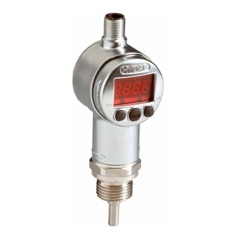
DELTA M microtuf FS4200 Series User manual

PROPRIETARY INFORMATION
THIS DOCUMENT IS THE PROPERTY OF DELTA M CORPORATION AND MAY
CONTAIN INFORMATION COVERED BY PATENTS AND/OR CONSIDERED
CONFIDENTIAL. UNLESS RIGHTS ARE EXPRESSLY GRANTED BY WRITTEN
PERMISSION OF DELTA M CORPORATION THIS INFORMATION IN WHOLE OR
IN PART MAY NOT BE DISCLOSED OR USED IN THE DESIGN, SALE,
MANUFACTURE, TEST, OR SUPPLY OF THE SAME OR SIMILAR PRODUCTS.
OPERATION AND MAINTENANCE MANUAL
microtuf®
MODEL FS4200 SERIES – MASS FLOW SWITCH
MODEL LS3200 SERIES – POINT LEVEL SWITCH
DOCUMENT 3242-OM-04
REVISION 4
MARCH 2002
DELTA M CORPORATION™
1003 LARSEN DRIVE
OAK RIDGE, TENNESSEE 37830
PH 865-483-1569
FAX 865-483-1142
TOLL FREE 800-922-0083
www.deltamcorp.com
email: service@deltamcorp.com
MODEL NO. SERIAL NO.
DATE OF SHIPMENT INSTALLATION DATE
CUSTOMER TAG NO. PO NO.
OPTIONS
SPECIAL NOTES

DELTA M Corporation 3242-OM-04 3/27/02
ii
BEFORE STARTING
DELTA M appreciates your choosing our product for your liquid level or liquid/gas flow switching
application. We are committed to providing reliable, quality instrumentation to our customers.
To ensure the maximum and intended benefit of this instrument, we encourage you to read this brief
operation and maintenance manual in its entirety prior to unpacking and installing the unit.
The following precautions should be noted immediately:
fUSE A 1 1/8 INCH (28.575mm) OPEN-END WRENCH TO TIGHTEN AT THE HEX FLATS OF
THE MNPT OF A STANDARD SWITCH. (IF YOU HAVE A NON-STANDARD SWITCH AN
ALTERNATE SIZE WRENCH MAY BE REQUIRED). DO NOT USE THE INSTRUMENT HEAD
TO TIGHTEN THE SWITCH TO THE MOUNTING PORT. ROTATION OF THE INSTRUMENT
HEAD WITH RESPECT TO THE SENSOR BODY CAN CAUSE INTERNAL WIRING DAMAGE
(SEE FIGURES 1).
fTHE SWITCH BODY MUST BE ORIENTED TO HAVE THE TWIN SENSORS PARALLEL TO
THE LEVEL BEING DETECTED WHEN BEING INSTALLED HORIZONTALLY FOR POINT
LEVEL APPLICATIONS. LIKEWISE, FOR FLOW APPLICATIONS, THE SWITCH BODY
MUST BE ORIENTED TO HAVE THE TWIN SENSORS PERPENDICULAR TO THE FLOW
BEING DETECTED. DUE TO THE PIPE THREAD MOUNTING, IT MAY BE NECESSARY TO
MAKE A TRIAL FIT, ADD OR REMOVE TEFLON TAPE OR OTHER PIPE THREAD
SEALANT, AND REINSTALL TO ACHIEVE A SATISFACTORY SEAL WITH THE SENSORS
PROPERLY ORIENTED. FOR VERTICAL INSTALLATIONS FOR POINT LEVEL
DETECTION THE ORIENTATION MAKES NO DIFFERENCE. PROPER ORIENTATION IS
MARKED ON THE SWITCH BODY FOR REFERENCE (SEE FIGURE 5).
fA GROUND WIRE MUST BE ATTACHED TO THE GROUND SCREW LOCATED INSIDE THE
INSTRUMENT ENCLOSURE FOR PROPER OPERATION. FOR CENELEC/CE OPTION THE
GROUND SCREW IS LOCATED OUTSIDE THE BODY OF THE INSTRUMENT ENCLOSURE
(SEE FIGURE 6).
fBE SURE TO APPLY THE PROPER VOLTAGE AS CONFIGURED AT THE FACTORY. DO
NOT APPLY 115 VAC TO 24 VDC VERSIONS OR 24 VDC TO 115 VAC VERSIONS.
(LIKEWISE 230 VAC).
fFOR OPTIMUM OPERATION, CALIBRATION MUST BE ACCOMPLISHED AT ACTUAL
PROCESS TEMPERATURE AND PRESSURE CONDITIONS IN GASES AND AT ACTUAL
PROCESS TEMPERATURE CONDITIONS IN LIQUIDS.
fDO NOT SANDBLAST OR ABRASIVE CLEAN THE SENSING PROBES. THE SENSING
PROBES COULD BE DAMAGED BY ABRASIVES.
ALL DIMENSIONS GIVEN IN THIS MANUAL ARE IN INCHES (AND MILLIMETERS).
If you have any questions prior to or during installation and calibration, please do not hesitate to call the
factory for assistance. We want to ensure the very best possible installation and operational results for
your benefit.

DELTA M Corporation 3242-OM-04 3/27/02
iii
The electronic assemblies contained in the microtuf
®
models are configured for specific voltages
and have specific modifications to accommodate the various agency approvals. When ordering
spare electronics, replacements, or exchanges in the field please ensure you identify the specific
configuration you have by noting the boxes marked on the transformer configuration tag.
NOTICE
This manual covers the following model numbers:
microtuf®Series Models FS4200 LS3200
Agency Approvals Explosion-Proof rating Mass Flow Switch Point Level Switch
CENELEC EEx d IIB T4 (Killark Enclosure)
European EEx d IIC T4 (Akron Electric Enclosure) FS42CN LS32CN
See Figure 1A and 1B
CSA T4A
Canadian Standards Class I, Group B,C,D FS42CS LS32CS
Class II, Group E,F,G
(Both Akron Electric and Killark)
Non-Approved Non-Explosion Proof FS42NX LS32NX
Switch Kits Not Rated FS42SK LS32SK
(No Enclosures)
CE EMC Directive: 89/336/EEC Option – CE Option -CE
SPECIAL NOTICE

DELTA M Corporation 3242-OM-04 3/27/02
iv
TABLE OF CONTENTS
1.0 INTRODUCTION
2.0 DESCRIPTION
2.1 LEVEL SWITCHING
2.2 FLOW SWITCHING
3.0 INSTALLATION
3.1 MECHANICAL INSTALLATION
3.2 ELECTRICAL INSTALLATION
3.2.1 LOCAL ELECTRONICS (LE OPTION/STANDARD)
3.2.2 REMOTE ELECTRONICS (RE) OPTION
4.0 OPERATION AND CALIBRATION OF THE microtuf®SWITCH FOR FLOW APPLICATIONS
4.1 PRE-OPERATIONAL CHECKS
4.2 L.E.D. AND RELAY STATUS LOGIC (FAIL-SAFE)
4.3 CALIBRATION – FLOW
5.0 OPERATION AND CALIBRATION OF THE microtuf®SWITCH FOR POINT LEVEL
APPLICATIONS
5.1 PRE-OPERATIONAL CHECKS
5.2 L.E.D. AND RELAY STATUS LOGIC (FAIL-SAFE)
5.3 CALIBRATION – LEVEL
6.0 MAINTENANCE AND TROUBLE SHOOTING
6.1 CLEANING
6.2 TROUBLE SHOOTING
6.2.1 POWER AND CONTINUITY VERIFICATION
6.2.2 SENSOR/ELECTRONICS FUNCTIONALITY VERIFICATION
7.0 SPECIFICATIONS
8.0 WARRANTY AND SERVICE
8.1 WARRANTY
8.2 SERVICE
9.0 APPENDIX
9.1 VOLUME FLOW CONVERSION CHART
9.2 FLOW CONVERSION CHART
9.3 FLOW OF WATER THROUGH SCHEDULE 40 STEEL PIPE (AVAILABLE IN PRINTED
MANUAL ONLY)
9.4 MODEL NUMBER DESIGNATION AND AVAILABLE OPTIONS

DELTA M Corporation 3242-OM-04 3/27/02
1
1.0 INTRODUCTION
The DELTA M microtuf®Switch is the state-of-the-art in gaseous and liquid flow switching or
liquid level control. Flow or level detection is accomplished by using a high resolution
thermal differential technique. The sensor wetted parts are of durable 316 series stainless
steel, all welded construction with no moving parts. The switch is easy to install and adjust,
giving reliable, low maintenance performance in the most demanding applications.
2.0 DESCRIPTION
The microtuf®Switch uses a thermal differential technique to sense changes in the heat
transfer characteristics of a media. Figures 1A and 1B show the outline of the microtuf®
Switch. The sensor consists of a pair of matched, Resistance Temperature Detectors
(RTD's) encased in twin 316 series stainless steel tubes. One RTD is self-heated using a
constant DC current. The other RTD is unheated to provide an accurate process
temperature reference. The thermal differential created between the heated and reference
RTD pair is a function of the density and/or velocity of the media with which the sensor is in
contact. Other physical properties may have a secondary effect as well. The differential is
greatest at a no flow (or dry) condition and decreases as the rate of flow increases (or as a
liquid quenches the sensor/wet condition).
The DELTA M Corporation sensor excitation method relies on constant current to the heated
and reference sensors. Thus power to the heated sensor is not constant but changes
linearly with temperature as the sensor resistance changes. Temperature compensation is
accomplished by using the amplified reference sensor voltage which also changes linearly
with temperature, as a dynamic reference. During calibration dry/no flow and wet/full flow
conditions are impressed across the trip point potentiometer. Since this reference is not
fixed but is set with respect to the reference sensor voltage, as temperature changes the trip
point potentiometer voltage changes with temperature exactly the same as that of the heated
sensor voltage with which it is being compared. Thus full temperature compensation is
achieved with non constant power.

DELTA M Corporation 3242-OM-04 3/27/02
2
4.75 (120.65)
(2 PLACES)
(2 PLACES)
5.50 (139.7)
.25 (6.35) DIA. MOUNTING HOLES
MOUNTING
.75 (19.05)MNPT
2.42 (61.47)
2.0 (50.8)
LENGTH
.8 (20.32) REF.
6.1 (154.94) REF.
STD. INSERTION
3.875 (98.42)
STANDARD FITTING
SEE FIGURE 5
.75 (19.05) FNPT FIELD
WIRING CONNECTION
DRAWING FILE: MTF1A00.DWG/.FC
W
CORPORATION
FIGURE 1A LS3200/FS4200 microtuf®OUTLINE DIAGRAM STANDARD 2.0 INCH
INSERTION (KILLARK ENCLOSURE – NEMA 4-EExd 11B, T4)
(MTF1A00.DWG/.FCW)

DELTA M Corporation 3242-OM-04 3/27/02
3
G
4.50 (114.3) REF.
.10 (2.54) REF.
4.88 (123.95) REF.
2.00 (50.8) REF. .8 (20.32) REF.
6.0 (152.4) REF.
5.20 (132.08) REF.
6.31 (160.27) REF.
C
L
MOUNT STRAP (OPTIONAL)
DRAWING FILE: MTF1B00.DWG /.FC
W
DIMENSIONS IN INCHES
(
MILLIMETERS
)
CORPORATION
SEE FIGURE 5
FIGURE 1B LS3200/FS4200 microtuf®OUTLINE DIAGRAM STANDARD 2.0 INCH
INSERTION (AKRON ELECTRIC ENCLOSURE – NEMA 4X – EexdIIC, T4)
(MTF1B00.DWG/.FCW)

DELTA M Corporation 3242-OM-04 3/27/02
4
SIGNAL
VACUUM
AIR
HYDROCARBON LIQUIDS
WATER
LIQUID METALS
MEDIA
DECREASING THERMAL DISPERSION OR HEAT TRANSFER
0
DRAWING FILE: MTF2A0.DWG
2.1 Level Switching
The thermal differential created between the heated and reference unheated RTD pair is a
function of the liquid or gas medium with which the sensor is in contact.
The point level measurement application uses the heat transfer differences between two media
to detect liquid level. For example, air has a relatively poor heat transfer characteristic so the
heated sensor will become relatively hot. If the sensor is then immersed in water, the relatively
high heat transfer characteristics of water will cool the heated RTD surface causing a decrease
in the signal output.
This same rational applies for any two media in contact with the sensor. Each medium will
have its own characteristic heat transfer properties. As long as there is a reasonable
difference in the heat transfer properties between the two media, the microtuf®can discriminate
between them. Figure 2A shows the relative signal output of the microtuf®sensor to a range of
different media. The maximum difference in output occurs between vacuum and liquid metal.
However, a significant difference occurs between water and hydrocarbon liquids so the
microtuf ®
can be used to detect a water/hydrocarbon liquid-liquid interface. In general, the
interface between any two media with differing heat transfer properties can be detected.
FIGURE 2A: RELATIVE CHANGE IN RESPONSE OF A HEATED RTD IMMERSED
IN VARIOUS MEDIA

DELTA M Corporation 3242-OM-04 3/27/02
5
0
HYDROCARBONS
WATER
0.01 0.1 1.0 5.0
1.0 10.0 100.0 500
VELOCITY (FT./SEC.)
DRAWING FILE: MTF2B0.DWG
SIGNAL (mV)
SENSOR
SIGNAL
AIR
LIQUID (F/S)
(MM/S)
GAS (F/S)
(MM/S)
0.001
0.305
0.10
3.05
3.05
30.5
30.5
304.8
304.8
3048
1524
15,240
MAXIMUM
RANGE
2.2 Flow Switching
Most mass flow monitoring techniques calculate mass indirectly by measuring volumetric flow
such as gallons per minute or cubic cm per second, then either measure density separately or
calculate it from temperature measurements of the fluid and, finally, combine density and
volumetric flow to obtain mass flow. The DELTA M thermal-differential technique is one of two
methods that directly measure the mass flow. For ease of comparison most flow applications
are presented in terms of velocity which is independent of the flow cross sectional area (i.e.
feet per second (FPS)). The true mass flow equivalent would be FPS multiplied by density but
for simplicity FPS is used and density effects are ignored. This is normally not critical for flow
switching applications.
When the sensor is inserted into a liquid or gas the heated RTD is strongly affected by the
velocity of the medium. Flow past the heated RTD changes the heat transferred from the
surface of the sensor. This cooling effect reduces the temperature of the sensor. The
microtuf®compares this change to a preset flow trip point to switch the output. Figure 2B
shows the model FS4200 signal change vs. flow rate for air, light hydrocarbon liquids, and
water. The signal change vs velocity has the same general shape for all three media but the
change is larger for air and the sensitive range is different for each. For air and most
gaseous media the range is 0.1 to 500 feet per second (FPS). For most liquid media the
range is 0.01 to 5 FPS. Appendices in section 9.0 contain flow conversion information to
facilitate conversion from various units and pipe dimensions into flow velocity in feet per
second.
FIGURE 2B microtuf® MODEL FS4200 FLOW RESPONSE FOR THREE MEDIA AND
CALIBRATION SETTINGS FOR EACH

DELTA M Corporation 3242-OM-04 3/27/02
6
1000%
TRIP POINT
CALIBRATION
SIGNAL PROCESSINGELECTRONICS
0 FLOW/ DRY CAL. MAX.FLOW / WET CAL.
VCC
1NC
NO
2
3C
CONTACT2
4NC
NO
5
6C
CONTACT # 1
H
7
8N
POWER IN
RELAY
LED LIGHTS
RED
GREEN
AB
FAILSAFE LOGIC
RELAY DRIVER
VCC
VCC
1
RTNS
RTN
2
3
CS 4
C
HS
5
H
VCC
COMPARATOR
CURRENTSOURCES
SENSORS EXCIT. CURRENTS RETURN
9
10
PROBE
ENCLOSURE
POWER SUPPLY
VCC
SAFETY GROUND
TEST POINTS
6
TBA
DRAWING FILE: MTF3A00.DWG/.FCW
Figure 3.A shows a block diagram of the microtuf® switch.
Once the switch is set to respond to the minimum and maximum flow rates (or wet vs. dry
conditions), the trip point is set by adjusting the Trip Adjust Potentiometer. Solid state
electronics transform the flow (or wetting) induced temperature differential into a voltage that
is compared to a control voltage. Matching voltages cause actuation of a relay to indicate a
change in state (flow vs. no-flow or dry vs. wet).
FIGURE 3A: MICROTUF SERIES SWITCH BLOCK DIAGRAM
MODELS LS32CS/FS42CS, LS32CN/FS42CN, LS32NX/FS42NX,
AND LS32SK/FS42SK
(MTF3A00.DWG/.FCW)

DELTA M Corporation 3242-OM-04 3/27/02
7
1000%
TRIP POINT
CALIBRATION
SIGNAL PROCESSING ELECTRONICS
0 FLOW / DRY CAL. MAX.FLOW / WET CAL.
R10 R13
VCC
1NC
NO
2
3C
CONTACT2
4NC
NO
5
6C
CONTACT# 1
H
7
8N
POWER IN
RELAY
LED LIGHTS
RED
GREEN
AB
FAILSAFE LOGIC
RELAY DRIVER
VCC
VCC
1
RTNS
RTN
2
3
CS 4
C
HS
5
H
VCC
COMPARATOR
CURRENT SOURCES
SENSORS EXCIT. CURRENTS RETURN
9
10
PROBE
ENCLOSURE
POWER SUPPLY
VCC
SAFETYGROUND
H
N
FILTERED POWER
TEST POINTS
TBA
TBB
6
DRAWING FILE: MTF3B00.DWG
EMC FILTER
CE
APPROVED
SWITCHES
Figure 3B shows a block diagram of the microtuf® switch with the addition of an EMC filter
required for the CE options (see section 7.0).
FIGURE 3B: MICROTUF MODELS WITH THE CE OPTION SWITCH BLOCK DIAGRAM
(MTF3B00.DWG)

DELTA M Corporation 3242-OM-04 3/27/02
8
ELECTRONIC ASSY. CONNECTOR PLATE
ENCLOSURE ASSEMBLY
BLANK COVER
(STANDARD)
PROBE ASSEMBLY
DRAWING FILE: MTF400.DWG /.FCW
NHCN
ON
CN
C
CN
O
POWER REL1-1 REL1-2
-+
USE MIN. 75 DEG. C RATED
FIELD CONDUCTORS
1
1
AB
GREEN
RED
FUS E
RELAY
R13
H2
H1
N2
N1
R10
0
50
100
Q1
U1
U3
L1
R15
GND
J1
TP3
TP2
U2
TP1
TP4
Q6
J2
T1
U4
CAPTIVE SCREWS
(2 PLACES)
TRANSFORMER
FIELD WIRING (TBB)
SENSORS WIRING (TBA)
The instrument enclosure at the top of unit contains the microtuf®Switch electronics board
which is removable to access the terminal block and facilitate field wiring (see Figure 4.0).
For applications where the electronics must be located away from the sensors due to
elevated process temperature, accessibility, etc., another instrument head containing the
electronics is remotely located (See option RE-Remote Electronics section 3.2.2).
FIGURE 4 microtuf® SWITCH ASSEMBLY
(MTF400.DWG/.FCW)

DELTA M Corporation 3242-OM-04 3/27/02
9
3.0 INSTALLATION
3.1 Mechanical Installation
The standard microtuf®Switch has a .75 inch (19.05mm) MNPT mount designed for easy
installation through a threaded port. Optional configurations include .5” (12.7mm) or 1.0”
(25.4mm) MNPT and flange mounts. Conduit is recommended for all wiring to the switch.
*IMPORTANT*
USE A 1 1/8 INCH (28.575mm) OPEN-END WRENCH TO TIGHTEN AT THE
HEX FLATS OF THE MNPT OF A STANDARD SWITCH. (IF YOU HAVE A
NON-STANDARD SWITCH AN ALTERNATE SIZE WRENCH MAY BE
REQUIRED). DO NOT USE THE INSTRUMENT HEAD TO TIGHTEN THE
SWITCH TO THE MOUNTING PORT. ROTATION OF THE INSTRUMENT
HEAD WITH RESPECT TO THE SENSOR BODY CAN CAUSE INTERNAL
WIRING DAMAGE.
*IMPORTANT*
THE SWITCH BODY MUST BE ORIENTED TO HAVE THE TWIN SENSORS
PROPERLY ORIENTED. DUE TO THE PIPE THREAD MOUNTING, IT MAY
BE NECESSARY TO MAKE A TRIAL FIT, ADD OR REMOVE TEFLON
TAPE OR OTHER PIPE THREAD SEALANT, AND REINSTALL TO
ACHIEVE A SATISFACTORY SEAL WITH THE SENSORS PROPERLY
ORIENTED. PROPER ORIENTATION IS MARKED ON THE SWITCH BODY
FOR REFERENCE. SEE FIGURE 5.0 FOR DETAILS.

DELTA M Corporation 3242-OM-04 3/27/02
10
This page left blank intentionally.

DELTA M Corporation 3242-OM-04 3/27/02
11
FIGURE 5: PROPER ORIENTATION OF THE SENSOR PROBE FOR LEVEL AND
FLOW APPLICATION IS INDICATED BY THE ARROW ON THE FLAT OF
THE MOUNTING FITTING. (MTF500.DWG/.FCW)
AA
B
B
LEVEL APPLICATION
FOR VERTICAL MOUNTING
FOR HORIZONTAL MOUNTING
LEVEL APPLICATION
VIEW B-B
VIEW A-A
FLOW APPLICATION VIEW C-C
C
C
FLOW
NOTES:
THE ARROWS ON THE FLATS OF THE MOUNTING FITTING INDICATES:
1. FOR FLOW APPLICATION-THE DIRECTION OF FLOW.
2. FOR LEVEL APPLICATION WITH HORIZONTAL MOUNTING-THE DIRECT
I
OF VERTICAL TO THE LEVEL SURFACE.
3. FOR LEVEL APPLICATION WITH VERTICAL MOUNTING-THE DIRECTION
OF THE ARROW HAS NO SIGNIFICANCE.
DRAWING FILE: MTF500.DWG/.
F
CORPORATION
CORPORATION
CORPORATION

DELTA M Corporation 3242-OM-04 3/27/02
12
1098765432 1
NO CON
NO CON
-
+
C
NO
NC
SAFETYGND
POWER
WIRING CONNECTIONS (NOTE 4)
TBB
654
321
HOT
SENSOR
TBA
SAFETY GROUND
TERMINAL BLOCK
LOCATIONS
TBB
TBA
INSTRUMENT HEAD
WITH COVER
REMOVED
TO SENSORS DRAWING FILE: MTF600.DWG/.FCW
COLD
SENSOR
C
NO
NC
RELAY
NHCN
ON
CN
C
CN
O
POWER REL1-1 REL1-2
-+
1
1
(NOTE 3)
(NOTE 2)
(NOTE 1)
(DPDT)
NH
CAUTION
USE SUPPLY WIRES SUITABLE
FOR 10 DEG. C ABOVE AMBIENT
3.2 Electrical Installation
3.2.1 microtuf®Local Electronics (LE Option/Standard)
Remove the instrument enclosure lid by unscrewing in a counter clockwise direction.
Unscrew (CCW) the printed circuit board captive screws (See Figure 4.0 for locations).
Remove the PC board by grasping the transformer and pulling it straight out. Connect
power and alarm relay wiring to Terminal Block (TBB) as shown in Figure 6.0. Reinstall the
microtuf®Switch electronics and tighten the captive screws.
FIGURE 6.0 microtuf®SWITCH LOCAL ELECTRONICS FIELD WIRING DIAGRAM
(MTF600FCW/.DWG)
NOTES:
1. Connections to sensors terminal block A (TBA) are factory installed and should
not be disconnected in the field. Note Jumpers 1-2, 3-4, and 5-6 must be in place
on TBA for proper operation of local electronics.
2. For 24 VDC operation (factory prepared), connect +positive to TBB7 and –negative
return to TBB8. For 115 VAC or 230 VAC connect hot to TBB7 and neutral to
TBB8.
3. Connect ground wire to ground screw located in or on the instrument enclosure.
4. Use supply wires suitable for 10 Degree C above ambient.
*IMPORTANT*
A GROUND WIRE MUST BE ATTACHED TO THE GROUND SCREW
LOCATED INSIDE OR OUTSIDE OF THE INSTRUMENT ENCLOSURE FOR
PROPER OPERATION.

DELTA M Corporation 3242-OM-04 3/27/02
13
The electronic assemblies contained in the microtuf®models are configured for specific voltages and have
specific modifications to accommodate the various agency approvals. When ordering spare electronics,
replacements, orexchanges in the field please ensure you identify the specific configuration you have by
noting the boxes marked on the transformer configuration tag.
3.2.2 Remote Electronics (RE Option)
For the remote electronics option, mount the remote instrument head using two mounting
wings or bracket provided. Connect the switch wiring between the microtuf®Switch remote
electronics as shown in Figure 7.0. Connect power wiring and alarm relay wiring to the
remote enclosure as shown in Figure 7.0. Upon completion of wiring reinstall the microtuf®
Switch electronics and secure with the captive screws.
*IMPORTANT*
BE SURE TO APPLY THE PROPER VOLTAGE AS CONFIGURED AT THE
FACTORY. DO NOT APPLY 115 VAC TO 24 VDC VERSIONS OR 24 VDC
TO 115 VAC VERSIONS (LIKEWISE 230 VAC).
SPECIAL NOTICE

DELTA M Corporation 3242-OM-04 3/27/02
14
FIGURE 7A microtuf
®
FLOW SWITCH REMOTE ELECTRONICS OPTION FIELD WIRING
DIAGRAM (MTF701.DWG/.FCW)
10987654321
NO CON
NO CON
-
+
C
NO
NC
POWER
TBB
654
321
HOT
SENSOR
TBC
TBB
TBA
TO SENSORS
SAFETY GND
TBC
REMOTE PROBE
WITH COVER REMOVED
REMOTE ELECTRONICS
WITH HEAD WITH COVER
REMOVED
3/4 (19.05MM) INCH CONDUIT
CONNECTION FOR REMOTE
ELECTRONICS TO SWITCH
SENSOR WIRING
213
4TBA
65
COLD
SENSOR
SHIELDS CONNECTED TO
TBA TERMINAL #5 ATTHIS END
3 TWISTED SHIELDED PAIRS CABLE
(PROVIDED BYDELTA M)
300°
MAX
SHIELDS FL0ATING
ATTHIS END
SAFETYGND
WIRING CONNECTION
DETAILS (NOTE 4)
REMOTE
ELECTRONICS
INSTRUMENT
HEAD
JUMPERS
(NOTE 1)
123456
REMOTE
PROBE
RELAY
C
NO
NC
NHCN
ON
CN
C
CN
O
POW ER R EL1- 1 REL 1 -2
-+
CAUTION
FOR 10 DEG. C ABOVE AMBIENT
1
1
CAUT ION
FOR 10 DEG. C ABOVE AMBIENT
DRAWING FILE: MTF701.DWG/.FCW
(NOTE 2)
(NOTE 1)
(NOTE 3)
NOTES:
1. JUMPER WIRES 1-2, 3-4, AND 5-6 MUST BE IN PLACE ON TBC IN THE REMOTE PROBE
FOR PROPER OPERATION OF THE REMOTED ELECTRONICS.
2. FOR 24VDC OPERATION (FACTORY PREPARED), CONNECT + POSITIVE TO TBB7 AND - NEGATIVE
RETURN TO TBB8. FOR 115VAC OR 230 VAC CONNECT HOT TO TBB7 AND NEUTRAL TO TBB8.
3. CONNECT GROUND WIRE TO GROUND SCREW LOCATED IN OR ON THE INSTRUMENT ENCLOSURE.
NH
USE SUPPLY WIRES SUITABLE
USE SUPPLY WIRES SUITABLE
4. USE SUPPLY WIRES SUITABLE FOR 10 DEGREE C ABOVE AMBIENT.

DELTA M Corporation 3242-OM-04 3/27/02
15
FIGURE 7B microtuf® REMOTE ELECTRONICS CABLE TERMINATION AND
CONNECTIONS
2.00
GREEN
BLACK
SHIELD LEAD W IRES
WHITE
BLACK
RED
BLACK
3/8" ( 9.5 mm)
CUT TEFLON SLEEVE SLIDE SLEEVE OUT CUT SHIELD FOILS OUT STRIP WIRES ENDS 3/8" (9.5 mm)
ACTIONS COMMON TO BOTH ENDS
ABCD
GREEN
BLACK
WHITE
BLACK
RED
BLACK
E
GREEN + SHIELD
BLACK
WHITE
BLACK
RED
BLACK
COVER SHIELD AND GREENWIRES WITHSHRINK TUBING (2)
H
CUT SHIELD LEAD WIRES
GREEN
BLACK
WHITE
BLACK
RED
BLACK
F
PROBE END ELECTRONIC ASSEMBLY END
GREEN + SHIELD
BLACK
SHIELD LEAD W IRE
WHITE
BLACK
RED
BLACK
SOLDER SHIELD LEAD WIRES CLOSE TO CABLE SLEEVE
G
SOLDER SHIELD AND GREENWIRES AT THE END
FINISH WITH SHRINK TUBING
FINISH END OF CABLE WITH SHRINK TUBING (1)
GREEN
BLACK
WHITE
BLACK
RED
BLACK
PROBE END
GREEN + SHIELD
BLACK
WHITE
BLACK
RED
BLACK
FINISHED CABLE
ELECTRONIC ASSEMBLY END
OAK RIDGE, TN 37830
DW G. NO.
DATE
PAGE:
AND MAY CONT AIN I NFORMAT ION COVERED BY PAT ENT S AND/OR
CONSIDERED CONFIDENTIAL. UNLESS RIGHT S ARE EXPRESSLY
GRANTEDBY W RIT T EN PERMISSION OF DELTA M CORPORATION,
T HIS INFORMATION IN WHOLE OR PART MAY NOT BE DISCLOSED
OR USED IN T HE DESI GN, MANUFACT URE, T EST , OR SUPPLY OF
THE SAME OR SIMILAR PRODUCTS.
PROPRIETARY INFORMATION
THIS DOCUMENT IS T HE PROPERT Y OF DELT A M CORPORATION
REVISION
SIZE
ALLDIMENSIONS ARE ININCHES
UNLESS OTHERWISE SPECIFIED
T OLERANCES
DECIMALS: .X _.030
.XX _.020
.XXX _.010
FRACT IONS: _ 1/32
ANGULAR: _ 0'-30'
DO NO T SCA LE T HI S DRAW I NG
APPROVALS
FINISH:
REVISEDBY
REV.
DATE:
DATE:
DATE:
DATE:
DATE:
DESIGNEDBY:
DRA W N BY :
DOCUMENT CONTROL:
SCALE:
OF
EN GINEE RIN G:
DE PT . MANA GER:
B
1003 LARSENDRIVE
ECONUMBER APPROVED
DI RECT O RY: FILE :
TIN ALL STRIPED WIRE ENDS
112
NHCN
ON
CN
C
CN
O
POWER R EL 1-1 R EL 1-2
-+
CAUT ION: Use s upply wires s uitable
for10 °C above surrounding ambient
1
1
PROBE CONNECTOR PLATE ELECTRONICS CONNECTOR PLATE
STANDARD TEMP. PROBE
CABLE
SRINK TUBE 1
SRINK TUBE 2
MED. & HIGH TEMP PROBES
(MAX. AMBIENT / ENCLOSURE TEMP. 75 °C) (MAX. AMBIENT / ENCLOSURE TEMP. 200 °C)
DELTA M PART # 101567 DELTA M PART # 101539
(50 mm)
MATERIALS
AND CONNECTIONS
MTF1100.FCW/DWG
GREG COX/R.BODINE
D. McCOY
03-12-00
03-15-00
REMOTE ELECTRONICS CABLE
TERMINATION AND CONNECTIONS
MTF11 00
none
11
USE: 3242OM- FIG. 11
TO SENSORS
5100 - OM
PVC, 1/4" (13 mm) OD TEFLON, 1/4" (13 mm) OD
PVC, 1/8" (6.5 mm) OD TEFLON, 1/8" (6.5 mm) OD
SPECIAL NOTE:
DURING THE INTERCONNECTIONPROCESS, USE ANY APPROPIATE METHOD
TO INSURE THAT THE CORRESPONDING BLACK WIRE OF EACH PAIR IS WIRED
TO THE CORRECT TERMINALS.
O. GARCIA 03-19-00
1
CAUT ION: Use supply wires suitable
for 10 °C above surrounding ambient
CORPORATION

DELTA M Corporation 3242-OM-04 3/27/02
16
NOTES: 1. Connections to sensors terminal block A (TBA) are factory installed and should
not be disconnected in the field. Note Jumpers 1-2, 3-4, and 5-6 must be in place
on TBA for proper operation of local electronics.
2. For 24 VDC operation (factory prepared), connect +positive to TBB7 and –negative
return to TBB8. For 115 VAC or 230 VAC connect hot to TBB7 and neutral to
TBB8.
3. Connect ground wire to ground screw located in or on the instrument enclosure.
4.0 OPERATION AND CALIBRATION OF THE microtuf®FS4200 SWITCH FOR
FLOW APPLICATIONS
4.1 Pre-Operational Check
With the switch installed and process conditions at no-flow, the following procedure can be
used to verify preliminary operation.
4.1.1 Remove the instrument enclosure cover by turning counter clockwise (ccw) to expose the
microtuf®Switch electronics.
4.1.2 Turn on power at its source.
4.1.3 Observe that either the red or green LED comes on.
4.1.4 If neither lamp illuminates refer to the trouble shooting Section, 6.2.
4.2 L.E.D. and Relay Status Logic (Fail-safe)
4.2.1 The L.E.D.s (Red; Green) are an indication of the sensors status (ie. flow below the setpoint
or flow above the set point) and are not affected by the position of the failsafe jumper J-2.
The failsafe jumper J-2 changes the relay activation status allowing the user to select the
failsafe power off condition most appropriate to the application. Refer to the tables below
that show the logic conditions between the sensors, L.E.D. lights, relay coil and contacts for
each position of the failsafe jumper J-2.
4.2.2 Normal Operation (as set at factory)
The switch comes configured from the factory with the following operation with the J-2
jumper in the B(2-3) position. (Refer to Figure 8.0.)
RELAY
RED GREEN RELAY CONTACT
SENSOR STATUS LED LED COIL STATUS STATUS
oNC
No Flow or Flow Below Set Point ON OFF Activated
oNO
oNC
Flow or Flow Above Set Point OFF ON Deactivated
oNO
This manual suits for next models
10
Table of contents
