Omron D40A-G9SX-NS - User manual

CSM_D40A_G9SX-NS_DS_E_3_2
1
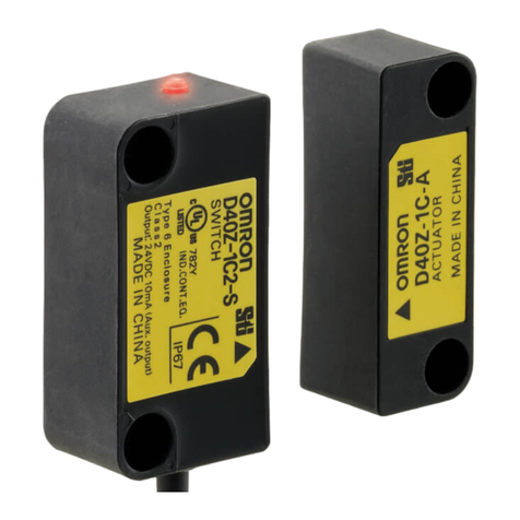
Compact Non-Contact Door Switch/Flexible Safety Unit
D40A/G9SX-NS
Electronic Detection Mechanism for
Better Stability in Non-contact Door
Switch Operation
Features
Be sure to read the “Safety Precautions” on page 24 and
the “Precautions for All Safety Door Switches”.
●
Easy-to-see 2-Color Indicators
Switch status is easy to see at a glance with
these red/yellow LED indicators.
Red:
Open door
detected.
Yellow:
Closed door
detected.
Not lit:
Power OFF
or failure
●
Small Actuator
An actuator that is smaller than the switch
saves space, even inside the door.
Even when mounted with an L-bracket, the
actuator's height will not hinder installation or
operation.
●
Connect Up to 30 Switches to a Single Controller
Up to 30 Switches
Reduce costs by connecting up to 30 Switches to a single Controller.
●
Mount from Either Side
Compact
Switch Actuator
Swinging doorsSwinging doors Sliding doorsSliding doors
Mount from whichever side provides the
easiest wiring path to enable mounting to all
types of doors.

D40A/G9SX-NS
2
Solves Conventional Switch Issues to Provide Stable Detection
The Switch doesnot accurately detect the door when it isclosed slowly, resulting in an error.
Issue 1
Door
closed
slowly.
An error can occur
if the door isclosed
slowly with
conventional
switches.
Conventional switch
The D40A doesnot use reed switchesand
providesstable detection with electronic switches.
Conventional Switches
Detectsslow rotating operation.
Solution 1
Slow
Magnet
Reed switch contactsReed switch contacts
Magnet If the switching timing of reed
switch contacts1 and 2 varies
too much, the Controller
detectsan error and turnsOFF
the output to maintain safety.
Note: The figure isintended
only as an illustration.
Stable Detection
with the D40A's
New System
Slow
Detectsslow lateral operation.
Error
Error
It isnearly impossible to tell which door isopen in a multi-door application.
Issue 2
If an error occurs...
It'simpossible to tell if there isadoor open or if an error has occurred.
The system cannot be started because the Controller has turned
OFF the output even though all doorsappear to be closed.
All doorsmust be opened and closed before operation can be started.
With the D40A...
Solution 2
The auxiliary outputscan be used to easily indicate which door is
open.
And with two-color indicators, mounting adjustmentsare also easy.
The D40A isthe first Non-contact Door Switch to combine 2-color
indicators, auxiliary outputs, and 30-switch connection capacity,
allowing youto create abetter safety environment.

3
D40A/G9SX-NS
Two Types of Controller to Solve Productivity, Expandability, and Maintenance Issues
The G9SX-NS and G9SX-NSA are designed specifically for use with the D40A, and with the G9SX-NSA you can also connect mechanical safety
door switches. Among other features, these Controllers support logical AND connections that enable partial stops. These Controllers make the
most of D40A Switches.
●
Two Different Controllers
G9SX-NS
@D40A input
@Two instantaneous
safety outputs
@Logical AND
connection output
G9SX-NSA
@D40A plus mechanical
safety door switch input,
channel 1 or 2
@Two instantaneous safety
outputs
@Two OFF-delay safety
outputs
@Logical AND
connection input
@Logical AND
connection output
@Logical AND
connection input
●
Expansion Unitsto Easily Increase the Number of Outputswith the G9SX-NSA
●
Mechanical Safety Door SwitchesCan Also Be Connected with the G9SX-NSA
●
IndicatorsThat Make Maintenance Easier
Up to 25 Outputs
G9SX-EX Expansion Unit
Logical AND
connection error
Safety Door
Switches
D40A
The indicatorsshow the location
and cause of wiring errorsand
any other errorsthat are detected.
Auxiliary outputsfor errorsalso
contribute to reducing down time.
Inputscan be accepted
from both D40A Switches
and mechanical switchesto
reduce the number of
Controllersand costs.
The number of outputs
can be easily increased
using connectors.
Up to 25 outputscan be
configured.
Input error Output error

4
D40A/G9SX-NS
Reduce Costs with these New-Concept Controllers
*Always use a manual reset when using an emergency stop.
AB
AB
Two Controllersare required for emergency stop switchesand
non-contact door switches.
Issue 1
●One hazard.
●The system must be stopped
when either a door isopened
or an emergency stop switch
ispressed.
The D40A
Simplifiesthe
Configuration
With only one
G9SX-NSA222-T03@
Controller, both a
Non-contact Door Switch
and an emergency stop
switch can be connected.
The G9SA must be
added to connect the
emergency stop
switch.
Application
D40B-J1
Emergency
stop switch *
G9SA
D40A
G9SX-NSA
Emergency
stop switch *
Two
Controllers
D40B
One
Controller
Solution 1
Solution 2
Another Controller hasto be added to use an OFF-delay timer.
Issue 2
The G9SA must be
added to use an
OFF-delay timer.
G9SA
Wiring
OFF-delay
output
G9SA-321-T@
D40B-J1
Emergency
stop switch *
D40A
Emergency
stop switch *
G9SX-BC G9SX-NSA
Three
Controllers
Two
Controllers
The D40A
Simplifiesthe
Configuration
D40B
A Controller can be
eliminated because the
G9SX-NSA222-T03@
providesan OFF-delay
output.
Application
Logical AND
connection
●Two hazards.
●The power supply must be
turned OFF immediately when
the emergency stop switch is
pressed.
●When a door isopened, a stop
signal issent to only
servomotor B and then the
power supply isturned OFF.
Refer to G9SX for the features of the G9SX Series.

5
D40A/G9SX-NS
Model Number Structure
Model Number Legend
Non-Contact Door Switch (Switch/Actuator)
Non-Contact Door Switch Controller
OrderingInformation
Non-Contact Door Switches (Switch/Actuator)
Note: Must be used in combination with a G9SX-NS@Non-contact Door Switch Controller.
*1. PNP open-collector semiconductor output.
*2. Ask your OMRON representative for the connector models.
Non-Contact Door Switch Controllers (Controllers for D40A)
*1. P channel MOS FET transistor output
*2. The OFF-delayed output becomes an instantaneous output by setting the OFF-delay time to 0 s.
*3. PNP transistor output
*4. The OFF-delay time can be set in 16 steps as follows:
0/0.2/0.3/0.4/0.5/0.6/0.7/0.8/0.9/1.0/1.2/1.4/1.8/2.0/2.5/3.0 s
Expansion Units
*1. PNP transistor output
*2. The OFF-delay time is synchronized to the OFF-delay time setting in the connected Controller (G9SX-NSA222-T03-@).
1. Type
1: Standard model
2. Auxiliary outputs
C: 1NO (PNP transistor output)
3. Cable length
2: 2 m
5: 5 m
123
D40A - @@@
1234 5 6
G9SX - @@@@@@ - @@@ - @@
1. Functions
NS/NSA: D40A Controller
EX: Expansion Unit
2. Output Configuration
(Instantaneous Safety Outputs)
2: 2 outputs
4: 4 outputs
3. Output Configuration
(OFF-delayed Safety Outputs)
0: None
2: 2 outputs
4. Output Configuration
(Auxiliary Outputs)
1: 1 output
2: 2 outputs
5. Max. OFF-delay Time
D40A Controller
T03: 3s (Variable)
Expansion Unit
Blank: No OFF delay
T: OFF delay
6. Terminal Block Type
RT: Screw terminals
RC: Spring-cage terminals
Classification Appearance Auxiliary outputs Cable length Model
Standard models *2 Semiconductor outputs *1
2 m D40A-1C2
5 m D40A-1C5
Safety outputs *1
Auxiliary
outputs *3
Logical
AND
connection
input
Logical
AND
connection
output
Max. OFF delay
time *4
Rated
voltageTerminal block type Model
Instantaneous
OFF-delayed
*2
2
(Semi-
conductors)
02
(Semi-
conductors)
11
---
24 VDC
Screw terminals G9SX-NS202-RT
Spring-cage terminals G9SX-NS202-RC
2
(Semiconductors)
3.0 s Screw terminals G9SX-NSA222-T03-RT
Spring-cage terminals G9SX-NSA222-T03-RC
Safety outputs Auxiliary
outputs OFF-delay time Rated
voltageTerminal block type Model
Instantaneous OFF-delayed
4PST-NO --- 1
(Semiconductor) *1
---
24 VDC
Screw terminals G9SX-EX401-RT
Spring-cage terminals G9SX-EX401-RC
--- 4PST-NO *2Screw terminals G9SX-EX041-T-RT
Spring-cage terminals G9SX-EX041-T-RC

D40A/G9SX-NS
6
Specifications
Ratings and Characteristics (Non-contact Door Switches)
*1. This is the distance where the switch operates from OFF to ON when approaching and the distance where the switch operates from ON to
OFF when separating when the switch and actuator target marks are on the same axis, and the sensing surfaces coincide.
*2. Turns ON when the actuator is approaching. The G3R series of the SSR can be driven at an auxiliary output of 10 mA. Contact your OMRON
representative for details.
*3. For details, refer to item 5 on page 25.
Item Model D40A-1C@
Operating
characteristics
*
1
Operatingdistance OFF→ON 5 mm min.
Operatingdistance ON→OFF 15 mm max.
Differential travel Refer to “Detection Ranges” on page 11
Influence of temperature (max.) ±20% of operating distance at 23°C, within temperature range of −10 to 55°C
Ambient operatingtemperature −10 to 55°C (no icing or condensation)
Ambient operatinghumidity 25% to 85%
Insulation resistance (between charged parts and
case) 50 MΩmax. (at 500 VDC)
Dielectric strength (between charged parts and case) 1,000 VAC for 1 min
Vibration resistance 10 to 55 to 10 Hz (single amplitude: 0.75 mm, double
amplitude: 1.5 mm)
Shock resistance 300 m/s2min.
Degree of protection IP67
Material PBT resin
Mountingmethod M4 screws
Terminal screw tighteningtorque 1 N·m
Power consumption 0.6 W max.
Auxiliary outputs *224 VDC, 10 mA (PNP open-collector outputs)
LED indicators Actuator not detected (red); actuator detected (yellow)
Connection cables 2 m, 5 m
Number of connectable switches *330 max. (wiring length: 100 m max.)
Weight Switch: approx. 145 g, actuator: approx. 20 g (D40A-1C2)

7
D40A/G9SX-NS
Ratings (Non-contact Door Switch Controllers)
Power input
*Power consumption of loads not included.
Inputs
*1. Only applies to the G9SX-NSA222-T03-@. Refers to input other than that from the Non-contact Door Switch.
*2. Provide a current equal to or higher than that of the minimum applicable load of the connected input control device.
Outputs
*1. While safety outputs are in the ON state, the following signal sequence is output continuously for diagnosis.
When using the safety outputs as input signals to control devices (i.e. Programmable Controllers), consider the OFF pulse shown below.
*2. The following derating is required when Units are mounted side-by-side.
G9SX-NS202-@/G9SX-NSA222-T03-@: 0.4 A max. load current
Expansion Unit
Item Model G9SX-NS202-@G9SX-NSA222-T03-@G9SX-EX-@
Rated supply voltage 24 V DC
Operating voltage range −15% to 10% of rated supply voltage
Rated power consumption *3 W max. 4 W max. 2 W max.
Item Model G9SX-NS202-@/G9SX-NSA222-T03-@
Safety input *1 Operating voltage: 20.4 VDC to 26.4 VDC, internal impedance: approx. 2.8 kΩ*2
Feedback/reset input
Item Model G9SX-NS202-@/G9SX-NSA222-T03-@
Instantaneous safety output *1
OFF-delayed safety output *1
P channel MOS FET transistor output
Load current: 0.8 A DC max. *2
Auxiliary output PNP transistor output
Load current: 100 mA max.
ON
OFF
360 μs max.
Approx.100 ms
Item Model G9SX-EX-@
Rated load 250 VAC, 3 A/30 VDC, 3 A (resistive load)
Rated carry current 3 A
Maximum switching voltage 250 VAC, 125 VDC

D40A/G9SX-NS
8
Characteristics
*1. When two or more Units are connected by logical AND, the operating time and response time are the sum total of the operating times and
response times, respectively, of all the Units connected by logical AND.
*2. Represents the operating time when the safety input turns ON with all other conditions set.
*3. Represents the operating time when the logical AND input and the Non-contact Door Switch input turn ON with all other conditions set.
*4. This does not include the operating time or response time of G9SX-NS@that are connected.
*5. This does not include the operating time or response time of internal relays in the G9SX-EX-@.
*6. The failure detection time for 24 V short-circuit failure on the input to Non-contact Door Switches is 35 ms max.
If using the Switch for an application other than as a Door Switch, calculate the safe distance using a failure detection time of 35 ms.
Item Model G9SX-NS202-@G9SX-NSA222-T03-@G9SX-EX-@
Over-voltage category
(IEC/EN 60664-1) II II (Relay outputs 13to 43and 14
to 44: III)
Operatingtime (OFF to ON state) *1
100 ms max. (Logical AND
connection input ON and
Non-contact Door Switch input
ON)
50 ms max. (Safety input: ON) *2
100 ms max. (Logical AND
connection input ON and
Non-contact Door Switch input ON)
*3
30 ms max. *4
Response time (ON to OFF state) *1
15 ms max. (Logical AND
connection input: OFF)
20 ms max. (Non-contact Door
Switch input OFF) *6
15 ms max. (Safety input OFF and
logical AND connection input OFF)
20 ms max. (Non-contact Door
Switch input: OFF) *6
10 ms max. *4
ON-state residual voltage3.0 V max. (safety output, auxiliary output)
OFF-state leakage current 0.1 mA max. (safety output, auxiliary output)
Maximum wiringlength of safety
input, logical AND connection
input, and Non-contact Door Switch
input
100 m max. (External connection impedance: 100 Ωmax. and 10 nF max.)
Reset input time
(Reset button pressingtime) 100 ms min.
Accuracy of OFF-delay time *5--- Within ±5% of the set value Within ±5% of the set value
Insulation
resistance
Between logical AND
connection terminals,
and power supply input
terminals and other
input and output
terminals connected
together
20 MΩmin. (at 100 VDC)
---
Between all terminals
connected together and
DIN rail
100 MΩmin.
(at 500 VDC)
Dielectric
strength
Between logical AND
connection terminals,
and power supply input
terminals and other
input and output
terminals connected
together
500 VAC for 1 min.
---
Between all terminals
connected together and
DIN rail 1,200 VAC for 1 min
Between different poles
of outputs
---
Between relay outputs
connected together and
other terminals
connected together
2,200 VAC for 1 min
Vibration resistance 10 to 55 to 10 Hz, 0.375 mm single amplitude (0.75 mm double amplitude)
Shock
resistance
Destruction 300 m/s2
Malfunction 100 m/s2
Durability
Electrical ---
100,000 cycles min. rated load,
switching frequency: 1,800
cycles/hour)
Mechanical --- 5,000,000 cycles min. (switching
frequency: 7,200 cycles/hour)
Ambient operatingtemperature −10 to 55°C (no icing or condensation)
Ambient operatinghumidity 25% to 85%
Terminal tighteningtorque 0.5 N·m (For the G9SX-NS@-RT (with screw terminals) only)
Weight Approx. 125 g Approx. 200 g Approx. 165 g
9
D40A/G9SX-NS
Logical AND Connection
Note: See Logical AND Connection Combinations below for details.
*1. The number of G9SX-EX401-@Expansion Units or G9SX-EX041-T-@Expansion Units (OFF-delayed Model) not included.
*2. G9SX-EX401-@Expansion Units and G9SX-EX041-T-@Expansion Units (OFF-delayed Model) can be mixed.
Logical AND Connection Combinations
1. One logical AND connection output from a G9SX-NS@Controller
can be logical AND connected to up to four Controllers.
2. Any G9SX-NS@Controller that receives a logical AND connection
input can be logically connected to other Controllers on up to five
layers.
Note: The G9SX-NS@in the above diagram can be replaced by the
G9SX-AD@Advanced Unit.
For details on G9SX-AD@Advanced Units, refer to the
G9SX-series Flexible Safety Unit catalog. (Cat. No. J150).
3.The largest possible system configuration contains a total of 20
G9SX-NS@Controllers, G9SX-AD@Advanced Units, and
G9SX-BC Basic Units. In this configuration, each Controller or
Advanced Unit can have up to five Expansion Units.
Item Model G9SX-NS202-@G9SX-NSA222-T03-@G9SX-EX-@
Number of Units connected per logical
AND output 4 Units max. ---
Total number of Units connected by
logical AND *120 Units max. ---
Number of Units connected in series
by logical AND 5 Units max. ---
Max. number of Expansion Units
connected *2--- 5 Units max.
Maximum cable length for logical AND
input 100 m max. ---
G9SX-NS@
G9SX-NS@G9SX-NS@G9SX-NS@G9SX-NS@
G9SX-NS@
G9SX-NS@
G9SX-NS@
G9SX-NS@
G9SX-NS@
G9SX-@
G9SX-AD@
or
G9SX-NS@
G9SX-AD@
or
G9SX-NS@
G9SX-AD@
or
G9SX-NS@
G9SX-AD@
or
G9SX-NS@
G9SX-AD@
or
G9SX-NS@
G9SX-AD@
or
G9SX-NS@
G9SX-AD@
or
G9SX-NS@
G9SX-AD@
or
G9SX-NS@
G9SX-AD@
or
G9SX-NS@
G9SX-AD@
or
G9SX-NS@
G9SX-AD@
or
G9SX-NS@
G9SX-AD@
or
G9SX-NS@
G9SX-AD@
or
G9SX-NS@
G9SX-AD@
or
G9SX-NS@
G9SX-AD@
or
G9SX-NS@
G9SX-AD@
or
G9SX-NS@
G9SX-AD@
or
G9SX-NS@
G9SX-AD@
or
G9SX-NS@
G9SX-AD@
or
G9SX-NS@
Number of Unitsconnected
per logical AND output: 4
Unitsmax.
Number of Unitsconnected
in seriesby logical AND: 5
Unitsmax. Total number of Units
connected by logical AND:
20 Unitsmax.

D40A/G9SX-NS
10
Response Time and OperatingTime
1. G9SX-NS@
2. G9SX-NSA@
3. Multiple G9SX-NS@/NSA@Non-contact Door Switch Controllers
When multiple Controllers are logically connected with AND connections, the response time is the sum of the response times given in 1 and 2
above. (It is the same for the operating time.)
Non-contact Door
Switch input
Logical AND input
*1. The maximum response time is the time it takes the output to switch from ON to OFF after
the input switches from ON to OFF.
*2. The maximum operating time is the time it takes the output to switch from OFF to ON after
the input switches from OFF to ON.
Max. response time
(excludingExpansion
Units) *1
Max. operatingtime
(excludingExpansion
Units) *2
Non-contact Door Switch input 20 ms 100 ms
Logical AND input 15 ms 100 ms
*1. The maximum response time is the time it takes the output to switch from ON to OFF after
the input switches from ON to OFF.
*2. The maximum operating time is the time it takes the output to switch from OFF to ON after
the input switches from OFF to ON.
Max. response time
(excludingExpansion
Units) *1
Max. operatingtime
(excludingExpansion
Units) *2
Non-contact Door Switch input 20 ms 100 ms
Safety input 15 ms 50 ms
Logical AND input 15 ms 100 ms
D4NS
Safety input
Logical AND input
Non-contact Door
Switch input
D40A (1)
D40A (2)
D40A (3)
D4NS
Safety input
Safety output
(1)
Safety output (2)
Safety output (3)
Logical AND
(1)
Logical AND
(2)
Case 1
Response Time from When D40A (1) Turns from ON to OFF until Safety Output (2) Turns from
ON to OFF
(
Case 2
Response Time from When D4NS Turns from ON to OFF until Safety Output (3) Turns from ON
to OFF
20 ms + 15 ms = 35 ms
(D40A (1)) (Logical AND
connection (1))
15 ms + 15 ms + 15 ms = 45 ms
(D4NS) (Logical AND
connection (1))
(Logical AND
connection (2))

11
D40A/G9SX-NS
EngineeringData
Detection Ranges (Typical Characteristics Data)
Note: 1. The operating distance is the distance between the switch and actuator sensing surfaces.
2. Data in the diagram is typical data at an ambient temperature of 23°C. Actual operating values may vary.
The operating distance may be affected by ambient metal, magnet catches, and temperature.
Connections
Internal Connection
G9SX-NS202-@(Non-contact Door Switch Controller)
*1. Internal power supply circuit is not isolated.
*2. Logical AND input is isolated.
*3. Outputs S14 to S24 are internally redundant.
G9SX-EX401-@/G9SX-EX041-T-@
(Expansion Unit/Expansion Unit OFF-delayed Model)
*1. Internal power supply circuit is not isolated.
*2. Relay outputs are isolated.
G9SX-NSA222-T03-@
(Non-contact Door Switch Controller)
*1. Internal power supply circuit is not isolated.
*2. Logical AND input is isolated.
*3. Outputs S14 to S54 are internally redundant.
Internal Circuit Diagram
D40A-1C@
X
Y
Sensing surface
Target marks
16
14
12
10
8
6
4
2
0−6−4−20 2 46
Distance from the target mark on the switch X (mm)
Operating distance Y (mm)
ON
OFF
0
2
4
6
8
10
12
14
−15 −10 −50 51015
Distance from the target mark on the switch Z (mm)
Operating distance Y (mm)
ON
OFF
ZY
Sensing surface
Target marks
*3
*2
Logical AND
input
Safety output control Auxiliary
output control
Reset/Feedback
Input
Non-contact Door
Switch control
Power
supply
circuit
*1
D1 D2
X1L1A2 X2
S24S14
D3 D4
T31 T32 T33 T41 T42
A1
A2 X2
Power
supply
circuit Auxiliary
output
control
Safety
output
control
A1
K1
13 23 33 43
14 24 34 44
K2
Exp.
sig.
IN
Exp.
sig.
OUT
*1
*2
A1
A2
T11
S14 S24 S44 S54
L1 X1 X2
T12 T21 T22 T31 T32 T33
Y1 D1 D2 D3 D4
T41 T42
Power
supply
circuit
*1
*3
Safety
input 1
Safety output control Auxiliary
output control Expansion Unit
output control
Safety
input 2
Reset/Feedback
Input
Cross fault
detection
input
Logical
AND input
*2
Non-contact Door
Switch control
Internal circuit
Brown
Blue
White
Black
Ye l l o w

D40A/G9SX-NS
12
Dimensions and Terminal Arrangement (Unit: mm)
48
7.2 dia.
6
13
7.2 dia.
7.2 dia.
4838
Two, 4.2 dia.
12
17
9.5
7.2 dia.
38
20 Two, 4.2 dia.
25
13
(2) Indicator
Sensing surface
Sensing surface
Vinyl-insulated round cord, dia. 4,
5-conductor (conductor cross-sectional area:
0.2 mm2,Insulator diameter: 1.0 mm)
Standard length: 2 m/5 m
(2)
Non-contact Door Switch (Switch/Actuator)
D40A-1C2
D40A-1C5
(Switch)(Actuator)
No.
NS
FB
ERR
AND
EI
PWR
D4L1S24S14
A2X2T42T41
A1X1D2D1
D3T32 T33T31
G9SX-NS202
24VDC
23 max. 115 max.
100 max.
(6) (See note 2.)
(6) (See note 2.)
(22.5) *
FBPWR
AND
EI
NS
ERR
D4
A2
S14
T41
S24
T42
L1
X2
D3
T33T32T31
A1X1D2D1
Note: 1. Above outline drawing is for models with spring-cage terminals (-RC).
2. For models with spring-cage terminals (-RC) only.
*Typical dimension
Terminal arrangement
Non-contact Door Switch Controller
G9SX-NS202-@
No.
OFF-DELAY
L1S54S44S24S14 D4
A2T42T41T22T21
A1X2X1Y1T12T11
T33T31
T1
ERR
EI
AND
FB
ED
T2
PWR
T32 D2 D3D1
G9SX-NSA222-T03
24VDC
NS
0.5
0.4
0.3
0.2 3.0
2.5
2.0
1.8
1.4
1.2
1.0
0.9
0.8
0.6
0.7
0
(10) 115 max.
100 max.
35.5 max.
(6) (See note 2.)
(6) (See note 2.)
(35) *
FBPWR
T1
AND
EI
T2
NS
ED
ERR
S54
T41
S14
T21
S24
T22
S44
L1
T42
D4
A2
T33T32T31
X1Y1
T12T11
X2 A1
D1 D2 D3
Terminal arrangement
Non-contact Door Switch Controller
G9SX-NSA222-T03-@
Note: 1. Above outline drawing is for models with spring-cage terminals (-RC).
2. For models with spring-cage terminals (-RC) only.
*Typical dimension

13
D40A/G9SX-NS
23 max. 115 max.
100 max.
(6) (See note 2.)
(6) (See note 2.)
(22.5) *
Expansion Unit
G9SX-EX401-@
Expansion Unit (OFF-delayed Model)
G9SX-EX041-T-@
43332313
PWR
44
A2
14 24
A1
34
X2
EI
ERR
43332313
PWR
44
A2
14 24
A1
34
X2
ED
ERR
G9SX-EX041-T-@
(Expansion Unit
with OFF Delay)
G9SX-EX401-@
(Expansion Unit)
Terminal arrangement
Note: 1. Above outline drawing is for models with spring-cage terminals (-RC).
2. For models with spring-cage terminals (-RC) only.
*Typical dimension

D40A/G9SX-NS
14
Non-contact Door Switch and Non-contact Door Switch Controller Wiring
Example: Wiringa Single Switch
*The auxiliary output load current must be 10 mA max.
Example: WiringMultiple Switches
Connect Up to 30 Non-contact Door Switches
Wiringof Inputs and Outputs
White
G9SX-NS202-@
G9SX-NSA222-T03-@
Auxiliary output load *
D40A-1C@
D1 D2 D3 D4 A2
Black
Brown
Blue
Yel l o w
G9SX-NS202-@
G9SX-NSA222-T03-@
White
D1 D2 D3 D4
White
White
Black
Black
Black
Brown
Brown
Brown
Blue
Blue
Blue
Signal name Wire color Description of operation
Non-contact Door Switch
power supply input
Brown Supplies power to the D40A.
Connect to the D3and D4 terminal of the G9SX-NS@.
Blue
Non-contact Door Switch input White
Inputs signals from the G9SX-NS@.
The Non-contact Door Switch input must be ON as a required condition for the Non-contact
Door Switch output to be ON.
Non-contact Door Switch
output Black Turns ON and OFF according to actuator detection and the status of the Non-contact Door
Switch input.
Auxiliary output Yellow Turns ON when actuator is detected.

15
D40A/G9SX-NS
Wiringof Inputs and Outputs
G9SX-NS202-@
Signal name Terminal
name Description of operation Wiring
Power supply
input A1, A2 Connect the power source to the A1 and A2
terminals.
Connect the power supply plus (24 VDC) to the A1
terminal.
Connect the power supply minus (GND) to the A2
terminal.
Non-contact
Door Switch input
D1, D2,
D3, D4
All Non-contact Door Switch inputs connected to the
G9SX-NS@must be ON as a required condition for
the safety outputs to be ON. Otherwise the safety
outputs cannot be in the ON state.
Feedback/reset
input
T31, T32,
T33
To set the safety outputs in the ON state, the ON state
signal must be input to T33. Otherwise the safety
outputs cannot be in the ON state.
Auto reset
To set the safety outputs in the ON state, the signal
input to T32 must change from the OFF state to the
ON state, and then to the OFF state. Otherwise the
safety outputs cannot be in the ON state.
Manual reset
Logical AND
connection input T41, T42
A logical AND connection means that one unit (Unit
A) outputs a safety signal “a” to a subsequent unit
(Unit B) and Unit B calculates the logical AND (i.e.,
outputs the AND) of the signal “a” and safety signal
“b”, which is input to Unit B.
Thereby the logic of the safety output of Unit B is
(AND). (An AND of inputs “a” and “b” is output.)
To set the safety outputs of the subsequent Unit in the
ON state, its logical AND connection preset switch
must be set to AND (enable) and the high signal must
be input to T41 of the subsequent unit.
Instantaneous
safety output S14, S24
Turns ON/OFF according to the state of the safety
inputs, Non-contact Door Switch inputs, feedback/
reset inputs, and logical AND connection inputs.
During OFF-delay state, the Instantaneous safety
outputs are not able to turn ON.
Keep these outputs open when not used.
Logical AND
connection
output
L1 Outputs a signal of the same logic and at the same
time as the instantaneous safety outputs. Keep these outputs open when not used.
Auxiliary monitor
output X1 Outputs a signal of the same logic and at the same
time as the instantaneous safety outputs. Keep these outputs open when not used.
Auxiliary error
output X2 Outputs when the error indicator is lit or flashing. Keep these outputs open when not used.
D1 D2 D3 D4
White Black Brown Blue
Feedback loop
KM
+24 V
T31 T33T32
Feedback loop
KM +24 V
T31 T33T32
Reset
Switch
G9SX-NS/NSA
L1
A2
G9SX-NS/NSA
L1
T41 T42
A2
A2
G9SX-NS/NSA
Logical AND connection sig.
(1st layer)
Next unit (5 layers max.)
T41 T42
G9SX-NS/NSA
L1
T41 T42
Logical AND connection sig.
(2nd layer)
Next unit (4 unit max.)
Input b
Input a
Output (a)
Output (a&b)
Unit B
Unit A
Next unit (4 unit max.)

D40A/G9SX-NS
16
G9SX-NSA222-T03-@
ConnectingSafety Sensors
Safety sensors cannot be connected to safety inputs for the G9SX-NSA222-T03-@.
Signal name
Terminal
name
Description of operation Wiring
Power supply
input A1, A2 Connect the power source to the A1 and A2
terminals.
Connect the power supply plus (24 VDC) to the A1 terminal.
Connect the power supply minus (GND) to the A2 terminal.
Safety input 1 T11, T12
To set the safety outputs in the ON state, the high
state signals must be input to both safety input 1
and safety input 2. Otherwise the safety outputs
cannot be in the ON state.
Corresponds to Safety
Category 2
Corresponds to Safety
Category 3(without
short-circuit monitoring
between systems)
Safety input 2 T21, T22 Corresponds to Safety
Category 3(Cross fault
detecting mode (for safety
inputs))
Non-contact
Door Switch
input
D1, D2,
D3, D4
All Non-contact Door Switch inputs connected to
the G9SX-NS must be ON as a required condition
for the safety outputs to be ON.
Otherwise the safety outputs cannot be in the ON
state.
Feedback/reset
input
T31, T32,
T33
To set the safety outputs in the ON state, the ON
state signal must be input to T33.
Otherwise the safety outputs cannot be in the ON
state.
Auto reset
To set the safety outputs in the ON state, the signal
input to T32 must change from the OFF state to the
ON state, and then to the OFF state. Otherwise the
safety outputs cannot be in the ON state.
Manual reset
Logical AND
connection input
T41, T42,
T51, T52
A logical AND connection means that one unit (Unit
A) outputs a safety signal “a” to a subsequent unit
(Unit B) and Unit B calculates the logical AND (i.e.,
outputs the AND) of the signal “a” and safety signal
“b”, which is input to Unit B.
Thereby the logic of the safety output “b” is output.)
To set the safety outputs of the subsequent Unit in
the ON state, its logical AND connection preset
switch must be set to AND (enable) and the high
signal must be input to T41 of the subsequent unit.
Cross fault
detection input Y1
Selects the mode for the failure detecting (cross
fault detecting) function for the safety inputs of
G9SX corresponding to the connection of the cross
fault detection input.
Keep Y1 open when using T11, T21. (Cross fault detecting
mode (for safety inputs))
Connect Y1 to 24 VDC when not using T11, T21. (Wiring
corresponding to category 2 or 3, or when connecting safety
sensors)
Instantaneous
safety output S14, S24
Turns ON/OFF according to the state of the safety
inputs, feedback/reset inputs, and logical AND
connection inputs.
During OFF-delay state, the Instantaneous safety
outputs are not able to turn ON.
Keep these outputs open when not used.
OFF-delayed
safety output S44, S54
OFF-delayed safety outputs.
The OFF-delay time is set by the OFF-delay preset
switch.
When the delay time is set to zero, these outputs
can be used as non-delay outputs.
Keep these outputs open when not used.
Logical AND
connection
output
L1 Outputs a signal of the same logic and at the same
time as the instantaneous safety outputs. Keep these outputs open when not used.
Auxiliary
monitor output X1 Outputs a signal of the same logic and at the same
time as the instantaneous safety outputs. Keep these outputs open when not used.
Auxiliary error
output X2 Outputs when the error indicator is lit or flashing. Keep these outputs open when not used.
T11 T12 T21 T22
Y1
+24 V
+24 V
T11 T12 T21 T22
Y1
+24 V +24 V
+24 V
T11 T12 T21 T22
Y1
NC
D1 D2 D3 D4
White Black Brown Blue
Feedback loop
KM
+24 V
T31 T33T32
Feedback loop
KM +24 V
T31 T33T32
Reset
Switch
G9SX-NS/NSA
L1
A2
L1
T41 T42
A2
A2
G9SX-NS/NSA
Logical AND connection sig.
(1st layer)
Next unit (4 unit max.)
Next unit (5 layers max.)
T41 T42
L1
T41 T42
Logical AND connection sig.
(2nd layer)
Next unit (4 unit max.)
Input b
Input a
Output (a)
Output (a&b)
Unit B
Unit A
G9SX-NS/NSA
G9SX-NS/NSA

17
D40A/G9SX-NS
Operation
Functions
Logical AND Connection
A logical AND connection means that the G9SX outputs a safety
signal “a” to another G9SX, and that G9SX creates the logical AND of
safety signal “a” and safety signal “b.” The safety output of the
G9SX-NSA222-T03-@with the logical AND connection shown in the
following diagram is “a” AND “b.”
This is illustrated using the application in the following diagram as an
example. The equipment here has two hazards identified as Robot 1
and Robot 2, and it is equipped with Non-contact Door Switches and
an emergency stop button as safety measures. If the door to Robot 2
is opened, only Robot 2 is stopped (i.e., a partial stop). If the door to
Robot 1 is opened or the emergency stop button is pressed, both
Robot 1 and Robot 2 stop (i.e., a complete stop).
The actual situation using a G9SX for this application is shown in this
example.
Note: The logical AND setting on the G9SX-NS202-@must be set to
AND (enabled).
*A manual reset is required when an emergency stop is used.
ConnectingExpansion Units
•The G9SX-EX and G9SX-EX-T Expansion Units can be connected
to a G9SX-NSA222-T3-@Non-contact Door Switch Controller to
increase the number of safety outputs. (They cannot be connected
to a G9SX-NS202-@.)
•A maximum of five Expansion Units can be connected to one
G9SX-NSA222-T03-@. This may be a combination of G9SX-EX
instantaneous models and G9SX-EX-T OFF-delayed models.
•Remove the terminating connector from the receptacle on
G9SX-NSA222-T03-@and insert the Expansion Unit cable
connector into the receptacle. Insert the terminating connector into
the receptacle on the Expansion Unit at the very end (rightmost).
•When Expansion Units are connected to a Controller, make sure
that power is supplied to every Expansion Unit. (Refer to the
following diagram for actual Expansion Unit connection.)
a
ab
a (AND) b
G9SX-NSA222-T03-@
G9SX-NS202-@
Robot 1
Robot 2
Emergency stop button
Non-contact Door Switch 1
Non-contact Door Switch 2
G9SX-
NSA222-T03-@
Robot 1 Robot 2
Emergency
stop switch *D40AD40A
G9SX-
NS202-@
Expansion Unit
Terminating
connector
G9SX-NSA222-T03-@

D40A/G9SX-NS
18
SettingProcedure
1. Cross Fault Detection (G9SX-NSA222-T03-@)
Set the cross fault detection mode for safety inputs by shorting Y1
to 24 V or leaving it open.
When cross fault detection is set to ON, short-circuit failures are
detected between safety inputs T11-T12 and T21-22. When a
cross fault is detected, the following will occur.
(1) The safety outputs and logical AND outputs lock out.
(2) The LED error indicator is lit.
(3) The error output (auxiliary output) turns ON.
2. Reset Mode (G9SX-NS202-@/NSA222-T03-@)
Set the reset mode using feedback/reset input terminals T31, T32,
and T33.
Auto reset mode is selected when terminal T32 is shorted to 24 V
and manual reset mode is selected when terminal T33 is shorted
to 24 V.
3. SettingLogical AND Connection (G9SX-NS202-@/
NSA222-T03-@)
When connecting two or more Non-contact Door Switch
Controllers by logical AND connection, set the logical AND
connection preset switch on the Controller that is on the input side
(Unit B in the following diagram) to AND. The default setting of the
logical AND connection preset switch is set to OFF.
Note: A setting error will occur and Unit B will lock out if the logical
AND setting switch on the Unit B is set to OFF.
4. Settingthe OFF-delay Time (G9SX-NSA222-T03-@)
The OFF-delay preset time on G9SX-NSA222-T03-@is set from
the OFF-delay time preset switch (1 each on the front and back of
the Unit).
Normal operation will only occur if both switches are identically set.
An error will occur if the switches are not identically set. The default
setting of the OFF-delay time preset switch is set to 0 s.
Refer to the following illustration for details on setting switch positions.
G9SX-NSA222-T03-@
Cross fault
detection Wiring
OFF
Corresponds to
Safety Category 2.
Corresponds to
Safety Category 3.
ON
Corresponds to
Safety Category 3
(Cross fault detecting
mode (for safety
inputs)).
Y1
T22T21T12T11
+24 V
+24 V
Y1
T22T21T12T11
+24 V
+24 V +24 V
Y1
T22T21T12T11
+24 V
+24 V
Auto reset mode
KM1
KM2
KM3
KM4
KM5
KM1
KM2Reset
switch
KM3
KM4
KM5
T33T32T31T33T32T31
Manual reset mode
Unit A
Unit B
L1 A2
T41 T42
AND
OFF
AND
OFF
Switch
Switch
Front Back
Example 2: 0.8-secondExample 1: 0-second
OFF-DELAY
0.5
0.4
0.3
0.2 3.0
2.5
2.0
1.8
1.4
1.2
1.0
0.9
0.8
0.6
0.7
0.5
0.4
0.3
0.2
0.6
0.7
03.0
2.5
2.0
1.8
1.4
1.2
1.0
0.9
0.8
0
OFF-DELAY
Notch

19
D40A/G9SX-NS
LED Indicators
*Refer to “Fault Detection” on the next page for details.
Settings Indication (at Power ON)
Settings for the G9SX can be checked by the orange indicators for approx. 3seconds after the power is turned ON. During this settings indication
period, the ERR indicator will light, however the auxiliary error output will remain OFF.
MarkingColor Name G9SX-NS202 G9SX-
NSA222 G9SX-EX G9SX-EX-T Function
Reference
PWR Green Power supply
indicator ❍❍❍❍Lights while power is supplied. ---
T1 OrangeSafety input #1
indicator --- ❍--- ---
Lights while a high signal is input to T12.
Flashes when an error relating to safety
input #1 occurs.
*
T2 OrangeSafety input #2
indicator --- ❍--- ---
Lights while a high signal is input to T22.
Flashes when an error relating to safety
input #2 occurs.
NS Orange
Non-contact Door
Switch input
indicator
❍❍--- ---
Lights when the Non-contact Door Switch
input turns ON. Flashes when an error
relating to the Non-contact Door Switch
input occurs.
FB OrangeFeedback/reset
input indicator ❍❍--- ---
Lights in the following cases:
With automatic reset while a high signal is
input to T33.
With manual reset while a high signal is
input to T32.
Flashes when an error relating to feedback/
reset input occurs.
AND OrangeLogical AND input
indicator ❍❍--- ---
Lights while a high signal is input to T41.
Flashes when an error relating to logical
AND connection input occurs.
EI Orange
Instantaneous
safety output
indicator
❍❍❍---
Lights while the Instantaneous safety
outputs (S14, S24, S34) are in the ON state.
Flashes when an error relating to the
instantaneous safety output occurs.
ED Orange
OFF-delayed
safety output
indicator
--- ❍--- ❍
Lights while OFF-delayed safety outputs
(S44, S54) are in the ON-state.
Flashes when an error relating to
OFF-delayed safety output occurs.
ERR Red Error indicator ❍❍❍❍Lights or flashes when an error occurs.
Indicator Item Setting
position
Indicator
status Settingmode Settingstatus
T1
Cross fault
detection
mode
Y1 terminal
Lit Detection mode Y1 = open
Not lit Non-detection mode Y1 = 24 VDC
FB Reset mode T32 or T33
terminal
Lit Manual reset mode T33 = 24 VDC
Not lit Auto reset mode T32 = 24 VDC
AND
Logical AND
connection
input mode
Logical AND
connection
preset switch
Lit Enable logical AND input AND
Not lit Disable logical AND input OFF

D40A/G9SX-NS
20
Fault Detection
When the Non-contact Door Switch Controller detects a fault, the ERR indicator and/or other indicators light up or flash to inform the user about
the fault.
Check and take necessary measures referring to the following table, and then re-supply power to the Non-contact Door Switch Controller.
(G9SX-NS202-@/NSA222-T03-@)
ERR
indicator
Other
indicator Fault Expected causes of the fault Check points and measures to take
Flashes
---
Fault due to
electromagnetic
disturbance or of internal
circuits.
1. Excessive electromagnetic
disturbance
2. Failure of the internal circuit
1. Check the disturbance level around the G9SX
and the related system.
2. Replace with a new product.
Lights
T1 flashes
Fault involved with safety
input 1
1. Error in the wiring of safety input 1
2. Incorrect setting of cross fault
detection input
3. Failure of the circuit of safety input 1
1. Check the wiring to T11 and T12.
2. Check the wiring to Y1.
3. Replace with a new product.
T2 flashes
Fault involved with safety
input 2
1. Error in the wiring of safety input 2
2. Incorrect setting of cross fault
detection input
3. Failure of the circuit of safety input 2
1. Check the wiring to T21 and T22.
2. Check the wiring to Y1.
3. Replace with a new product.
NS
flashes
Fault involved with
Non-contact Door Switch
input
1. Error in the wiring of Non-contact
Door Switch input
2. Error in the wiring of Non-contact
Door Switch inputs in series
connections.
3. Failure of the internal circuits of
Non-contact Door Switch inputs
4. Failure of the Non-contact Door
Switch
1. Check the wiring to D1 and D2.
2. Check the wiring to the D40A.
3. Replace with a new product.
4. Replace with a new D40A.
FB
flashes
Fault involved with
feedback/reset inputs
1. Error in the wiring of feedback/reset
input.
2. Failure of the circuit of feedback/
reset input
1. Check the wiring to T31, T32 and T33.
2. Replace with a new product.
Fault in Expansion Unit
1. Improper feedback signals from
Expansion Unit
2. Abnormal supply voltage to
Expansion Unit
3. Failure of the circuit of safety relay
contact outputs
1. Check the connecting cable of Expansion Unit
and the connection of the termination socket.
2. Check the supply voltage to Expansion Unit.
Note: Make sure that all Expansion Units' PWR
indicators are lit.
3. Replace with a new product.
EI flashes
Fault involved with
instantaneous safety
outputs, logical AND
connection outputs, or
auxiliary monitor output
1. Error in the wiring of instantaneous
safety outputs
2. Failure of the circuit of instantaneous
safety outputs
3. Error in the wiring of the logical AND
connection output
4. Failure of the circuit of the logical
AND connection output
5. Error in the wiring of the auxiliary
monitor output
6. Impermissible high ambient
temperature
1. Check the wiring to S14 and S24.
2. Replace with a new product.
3. Check the wiring to L1.
4. Replace with a new product.
5. Check the wiring to X1.
6. Check the ambient temperature and spacing
around the G9SX.
ED
flashes
Fault involved with
OFF-delayed safety
outputs
1. Error in the wiring of OFF-delayed
safety relay contact outputs
2. Incorrect set values for OFF-delay
time
3. Failure of the circuit of OFF-delayed
safety relay contact outputs
4. Impermissible high ambient
temperature
1. Check the wiring to S44 and S54.
2. Check the settings of the OFF-delay time setting
switch.
3. Replace with a new product.
4. Check the ambient temperature and spacing
around the G9SX.
Other manuals for D40A-G9SX-NS -
1
This manual suits for next models
2
Table of contents
Other Omron Switch manuals

Omron
Omron D4NH - User manual

Omron
Omron A8GS-T Series User manual

Omron
Omron D4BL - User manual

Omron
Omron D41D User manual

Omron
Omron HL-5030 User manual

Omron
Omron D2MQ Series User manual

Omron
Omron D5B - User manual

Omron
Omron D4MC User manual

Omron
Omron D4D-R Series User manual

Omron
Omron D4BL - User manual