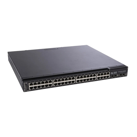
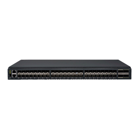
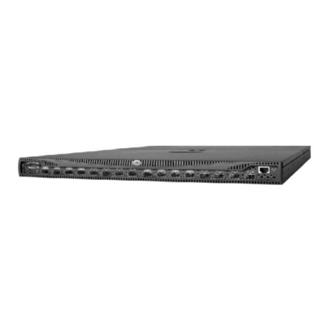
IBM Flex System EN4023 User manual

IBM Flex System EN4023 10Gb Scalable
Switch
User’s Guide


IBM Flex System EN4023 10Gb Scalable Switch
User’s Guide

Note: Before using this information and the product it supports, read the general information in Appendix B, “Notices,” the Safety
Information and Environmental Notices and User Guide documents on the IBM Notices for Network Devices CD, and the Warranty
Information document that comes with the product.
First Edition (November 2013)
© Copyright IBM Corporation 2013.
US Government Users Restricted Rights – Use, duplication or disclosure restricted by GSA ADP Schedule Contract with IBM Corp.

©Copyright IBM Corp. 2013 iii
Contents
Safety statements . . . . . . . . . . . . . . . . . . . . . . . . . . . . . . . . . . . . . . . . . . . . . . . viii
UL Regulatory Information . . . . . . . . . . . . . . . . . . . . . . . . . . . . . . . . . . . . . . . . . x
Chapter 1. IBM Flex System EN4023 10Gb Scalable Switch
Related documentation. . . . . . . . . . . . . . . . . . . . . . . . . . . . . . . . . . . . . . . . . . . . 1
Brocade documentation . . . . . . . . . . . . . . . . . . . . . . . . . . . . . . . . . . . . 2
Notices and statements . . . . . . . . . . . . . . . . . . . . . . . . . . . . . . . . . . . . . . . . . . . 3
Features and specifications . . . . . . . . . . . . . . . . . . . . . . . . . . . . . . . . . . . . . . . . 3
Features. . . . . . . . . . . . . . . . . . . . . . . . . . . . . . . . . . . . . . . . . . . . . . . . . 3
Model options . . . . . . . . . . . . . . . . . . . . . . . . . . . . . . . . . . . . . . . . . . . . 4
License options . . . . . . . . . . . . . . . . . . . . . . . . . . . . . . . . . . . . . . . . . . . 4
Dynamic Ports on Demand. . . . . . . . . . . . . . . . . . . . . . . . . . . . . . . . . . 5
Switch specifications . . . . . . . . . . . . . . . . . . . . . . . . . . . . . . . . . . . . . . 5
Memory and processor specifications. . . . . . . . . . . . . . . . . . . . . . . . . 5
Environmental conditions and specifications . . . . . . . . . . . . . . . . . . . 5
Switch components. . . . . . . . . . . . . . . . . . . . . . . . . . . . . . . . . . . . . . . . . . . . . . . 6
Product name and serial number. . . . . . . . . . . . . . . . . . . . . . . . . . . . . . . . . . . . 7
Chapter 2. Installing the Switch
Installation guidelines . . . . . . . . . . . . . . . . . . . . . . . . . . . . . . . . . . . . . . . . . . . . . 9
System reliability guidelines. . . . . . . . . . . . . . . . . . . . . . . . . . . . . . . . . 9
Handling static-sensitive devices. . . . . . . . . . . . . . . . . . . . . . . . . . . . 10
Installing the switch. . . . . . . . . . . . . . . . . . . . . . . . . . . . . . . . . . . . . . . . . . . . . .11
Installing and removing an SFP+ or QSFP transceiver . . . . . . . . . . . . . . . . . .13
Handling an SFP+ or QSFP transceiver . . . . . . . . . . . . . . . . . . . . . . . 14
Inserting an SFP+ or QSFP transceiver . . . . . . . . . . . . . . . . . . . . . . .15
Removing or replacing an SFP+ or QSFP transceiver. . . . . . . . . . . . 16
Cabling the switch . . . . . . . . . . . . . . . . . . . . . . . . . . . . . . . . . . . . . . . . . . . . . . . 17
Connecting and disconnecting the USB console cable . . . . . . . . . . 17
Connecting the RJ-45 Ethernet cable . . . . . . . . . . . . . . . . . . . . . . . .18
Locating the information panel, LEDs, and external ports . . . . . . . . . . . . . . . 19
Information LEDs. . . . . . . . . . . . . . . . . . . . . . . . . . . . . . . . . . . . . . . . .20
Port mapping . . . . . . . . . . . . . . . . . . . . . . . . . . . . . . . . . . . . . . . . . . . . 24
Configuring the switch. . . . . . . . . . . . . . . . . . . . . . . . . . . . . . . . . . . . . . . . . . . .25
Configuring an IP address on the switch using the CLI . . . . . . . . . .25
Configuring an IP address on the switch using the CMM GUI . . . . .26
Connecting to the switch over SSH . . . . . . . . . . . . . . . . . . . . . . . . . .28
Connecting to the switch using the serial console port . . . . . . . . . .29
Connecting to the switch using the RJ-45 Ethernet port . . . . . . . . .29

iv IBM Flex System EN4023 10Gb Scalable Switch User’s Guide
Initial configuration . . . . . . . . . . . . . . . . . . . . . . . . . . . . . . . . . . . . . . . . . . . . . .30
Logging in to the switch. . . . . . . . . . . . . . . . . . . . . . . . . . . . . . . . . . . . . . . . . . .30
Managing the switch . . . . . . . . . . . . . . . . . . . . . . . . . . . . . . . . . . . . . . . . . . . . . 31
SNMP v3 authentication. . . . . . . . . . . . . . . . . . . . . . . . . . . . . . . . . . . 31
Backing up the configuration . . . . . . . . . . . . . . . . . . . . . . . . . . . . . . . 31
Resetting the switch to factory defaults . . . . . . . . . . . . . . . . . . . . . .32
Removing or replacing the switch . . . . . . . . . . . . . . . . . . . . . . . . . . .33
Chapter 3. Updating the Firmware
Determining the switch firmware level. . . . . . . . . . . . . . . . . . . . . . . . . . . . . . .35
Determining firmware from the CMM . . . . . . . . . . . . . . . . . . . . . . . .35
Determining firmware from the switch using the CLI . . . . . . . . . . . .35
Upgrading the switch firmware. . . . . . . . . . . . . . . . . . . . . . . . . . . . . . . . . . . . .36
Chapter 4. Solving Problems
Running POST . . . . . . . . . . . . . . . . . . . . . . . . . . . . . . . . . . . . . . . . . . . . . . . . . .39
POST errors . . . . . . . . . . . . . . . . . . . . . . . . . . . . . . . . . . . . . . . . . . . . . . . . . . . .39
Parts listing . . . . . . . . . . . . . . . . . . . . . . . . . . . . . . . . . . . . . . . . . . . . . . . . . . . .40
Appendix A. Getting Help and Technical Assistance
Before you call . . . . . . . . . . . . . . . . . . . . . . . . . . . . . . . . . . . . . . . . . . . . . . . . . . 41
Using the documentation . . . . . . . . . . . . . . . . . . . . . . . . . . . . . . . . . . . . . . . . . 41
Getting help and information from the World Wide Web . . . . . . . . . . . . . . . .42
Software service and support . . . . . . . . . . . . . . . . . . . . . . . . . . . . . . . . . . . . .42
Hardware service and support . . . . . . . . . . . . . . . . . . . . . . . . . . . . . . . . . . . . .42
IBM Taiwan product service . . . . . . . . . . . . . . . . . . . . . . . . . . . . . . . . . . . . . . .42
Appendix B. Notices
Trademarks . . . . . . . . . . . . . . . . . . . . . . . . . . . . . . . . . . . . . . . . . . . . . . . . . . . .44
Important notes . . . . . . . . . . . . . . . . . . . . . . . . . . . . . . . . . . . . . . . . . . . . . . . . .45
Electronic emission notices . . . . . . . . . . . . . . . . . . . . . . . . . . . . . . . . . . . . . . .45
Federal Communications Commission (FCC) statement . . . . . . . . .45
Industry Canada Class A emission compliance statement . . . . . . .46
Avis de conformité à la réglementation d’Industrie Canada. . .46
Australia and New Zealand Class A statement . . . . . . . . . . . . . 47
European Union EMC Directive conformance statement . . . . . 47
Germany Class A statement . . . . . . . . . . . . . . . . . . . . . . . . . . . . 47
Japan VCCI Class A statement . . . . . . . . . . . . . . . . . . . . . . . . . .48
Korea Communications Commission (KCC) statement. . . . . . .49
Russia Electromagnetic Interference (EMI) Class A
statement . . . . . . . . . . . . . . . . . . . . . . . . . . . . . . . . . . . . . . . . . . .49
People’s Republic of China Class A electronic emission
statement . . . . . . . . . . . . . . . . . . . . . . . . . . . . . . . . . . . . . . . . . . .49
Taiwan Class A compliance statement. . . . . . . . . . . . . . . . . . . .49

©Copyright IBM Corp. 2013 vii
Safety
Bu ürünü kurmadan önce güvenlik bilgilerini okuyun.
Youq mwngz yungh canjbinj neix gaxgonq, itdingh aeu doeg aen
canjbinj soengq cungj vahgangj ancien siusik.

viii IBM Flex System EN4023 10Gb Scalable Switch User’s Guide
Safety statements
Safety statements
Important:
Each caution and danger statement in this document is labeled with a number. This number is
used to cross-reference an English-language caution or danger statement with translated versions
of the caution or danger statement in the Safety Information document.
For example, if a caution statement is labeled “Statement 1,” translations for that caution
statement are in the Safety Information document under “Statement 1.”
Be sure to read all caution and danger statements in this document before you perform the
procedures. Read any additional safety information that comes with the server or optional device
before you install the device.
This device is intended for use with UL Listed IBM Flex Systems.
Statement 1:
DANGER
Electrical current from power, telephone, and communication cables is hazardous.
To avoid a shock hazard:
•Do not connect or disconnect any cables or perform installation, maintenance, or
reconfiguration of this product during an electrical storm.
•Connect all power cords to a properly wired and grounded electrical outlet.
•Connect to properly wired outlets any equipment that will be attached to this product.
•When possible, use one hand only to connect or disconnect signal cables.
•Never turn on any equipment when there is evidence of fire, water, or structural damage.
•Disconnect the attached power cords, telecommunications systems, networks, and
modems before you open the device covers, unless instructed otherwise in the
installation and configuration procedures.
•Connect and disconnect cables as described in the following table when installing,
moving, or opening covers on this product or attached devices.
To Connect: To Disconnect:
1. Turn everything OFF. 1. Turn everything OFF.
2. First, attach all cables to devices. 2. First, remove power cords from outlet.
3. Attach signal cables to connectors. 3. Remove signal cables from connectors.
4. Attach power cords to outlet. 4. Remove all cables from devices.
5. Turn device ON

ix
Safety statements
Statement 3:
CAUTION:
When laser products (such as CD-ROMs, DVD drives, fiber optic devices, or transmitters) are
installed, note the following:
DANGER
Some laser products contain an embedded Class 3A or Class 3B laser diode.
Note the following.
Laser radiation when open. Do not stare into the beam, do not view directly
with optical instruments, and avoid direct exposure to the beam.
Class 1 Laser Product
Laser Klasse 1
Laser Klass 1
Luokan 1 Laserlaite
Appareil À Laser de Classe 1

xIBM Flex System EN4023 10Gb Scalable Switch User’s Guide
UL Regulatory Information
Statement 8:
CAUTION:
Never remove the cover on a power supply or any part that has the following label attached.
Hazardous voltage, current, and energy levels are present inside any component that has this label
attached. There are no serviceable parts inside these components. If you suspect a problem with
one of these parts, contact a service technician.
UL Regulatory Information
This device is for use only with Listed IBM Flex System Enterprise Chassis.

©Copyright IBM Corp. 2013 1
Chapter
1
IBM Flex System EN4023 10Gb Scalable Switch
The IBM Flex SystemTM EN4023 10Gb Scalable Switch is a high-density, 64-port, 10-Gbps Ethernet
switch that is used in the IBM Flex System chassis. The switch provides 42 internal ports to
compute nodes by way of the midplane, and 14 external SFP+ ports that are capable of running
10-Gbps Ethernet. Also included are two external Quad SFP (QSFP) ports that can support 40-Gbps
Ethernet or 4x10-Gbps Ethernet in breakout mode.
This User’s Guide contains information and instructions for installing the switch and getting the
switch up-and-running as quickly as possible. See the IBM Flex System Installation and Service
Guide that comes with your IBM Flex System chassis to install the switch in the chassis; then,
return to this User’s Guide for the information and instructions needed to complete the installation.
For information about the types of compatible devices available for IBM products, contact your IBM
marketing representative or authorized reseller. For a list of supported optional devices, see
http://www.ibm.com/servers/eserver/serverproven/compat/us/
For the most up-to-date product documentation for all of your IBM Flex System products, go to the
IBM Flex System Information Center at:
http://pic.dhe.ibm.com/infocenter/flexsys/information/index.jsp
NOTES:
•The IBM Flex System EN4023 10Gb Scalable Switch is also referred to as “the switch”
throughout this document.
•Changes are made periodically to the IBM®website. Procedures for locating firmware and
documentation might vary slightly from what is described in this document.
•The illustrations in this document might differ slightly from your hardware.
•The screens that are described or referenced in this document might differ slightly from the
screens that are displayed by your system. Screen content varies according to the type of
IBM Flex System chassis, and the firmware versions and options that are installed.
Related documentation
This User’s Guide contains setup and installation instructions for the IBM Flex System EN4023
10Gb Scalable Switch and general information about the switch, including how to configure,
update, and troubleshoot the switch, as well as how to get help. For the most up-to-date product
documentation for all of your IBM Flex System products, go to the IBM Flex System Information
Center at the following location: http://pic.dhe.ibm.com/infocenter/flexsys/information/index.jsp
The following IBM Flex System documentation is available:
•IBM Flex System Chassis Management Module Command-Line Interface Reference Guide
This document explains how to use the Chassis Management Module command-line interface
(CLI) to directly access management functions. The command-line interface also provides
access to the text-console command prompt on each compute node through a Serial over LAN
(SOL) connection.

2IBM Flex System EN4023 10Gb Scalable Switch User’s Guide
Related documentation
1
•IBM Flex System Chassis Management Module User’s Guide
This document explains how to use the Chassis Management Module (CMM) user interface to
manage chassis components.
•IBM Flex System Enterprise Chassis Installation and Service Guide
This document contains hardware installation instructions for the switches and pass-through
switches that install in the IBM Flex System chassis.
•IBM Flex System Manager System Management Guide
This document explains how to use the IBM Flex System Manager user interface to manage
chassis components.
•IBM Flex System network device User’s Guides
These documents contain detailed information about installing, configuring, updating, and
troubleshooting specific IBM Flex System network devices, which include network switches,
pass-thru switches, and adapters.
•Environmental Notices and User Guide
This document is provided on the IBM Notices for Network Devices CD, and it contains
translated environmental notices.
•Safety Information
This document is provided on the IBM Notices for Network Devices CD, and it contains
translated caution and danger statements. Each caution and danger statement that appears
in the documentation has a number that you can use to locate the corresponding statement in
your language in the Safety Information document.
•Warranty Information
This document comes with the network device, and it contains information about the terms of
the warranty.
Brocade documentation
Download the following Brocade Network Operating System publications referenced in this User’s
Guide through http://ibm.brocadeassist.com/public/NetworkOSv4xRelease
On this website, select the Documentation tab, select Network Operating System (NOS) from the
Download by list box, then select the appropriate version for your product.
•Network OS Administrator’s Guide
•Network OS Command Reference
•Network OS MIB Reference
•Network OS System Error Message Reference
•Network OS YANG Reference Manual
•Network OS NETCONF Operations Guide

Introduction 3
Notices and statements 1
Notices and statements
Features and specifications
The IBM Flex System EN4023 10Gb Scalable Switch supports the following features and
specifications.
Features
•64 10-Gbps Ethernet ports
•Up to 42 internal ports connected to 14 compute nodes at the midplane auto-negotiating to
10-Gbps Ethernet (available through Ports-On-Demand activation)
•Up to 14 external ports capable of supporting 1-Gbps Ethernet or 10-Gbps Ethernet through
10-Gbps SFP+ transceivers (available through Ports-On-Demand activation)
•2 Quad SFP (QSFP) ports that can support 40-Gbps Ethernet or 4x10-Gbps Ethernet in
breakout mode (available through Ports-On-Demand activation)
•Inter-Switch Link (ISL) Trunking, which allows up to eight ports (at 40-Gbps or 10-Gbps speeds)
to combine to form a single, logical ISL with a speed of up to 128 Gbps (256-Gbps full-duplex)
for optimal bandwidth utilization, automatic path failover, and load balancing
•Internal 1-Gbps full-duplex Ethernet port to connect to the redundant IBM Chassis
Management Modules (CMMs)
•Supports up to 640-Gbps I/O bandwidth
Notices for Network Device

4IBM Flex System EN4023 10Gb Scalable Switch User’s Guide
Features and specifications
1
•One external RS-232 console port with a mini-USB interface for serial console management
and diagnostics
•One external 10/100/1000Base-T RJ-45 Ethernet port with integral LEDs for link/activity and
speed for debugging and field support
•LEDs noting external port status and switch module status
•Up to four hot-pluggable switches per IBM Flex System chassis
•Brocade Network OS (NOS), which delivers distributed intelligence throughout the network and
enables a wide range of value-added applications, for example, virtualization features that are
distributed throughout a fabric, and multitenancy features. Requires Network OS version
4.0.0_bbd or later.
•Supports IBM Features on Demand
•Supports Ports on Demand (POD)
•SNMP v1, v2, and v3 support
•SSH v2 support
•NTP client support (NTP V3)
•FTP, SCP, and SFTP support for firmware upgrades
•SNMP/MIB monitoring functionality contained within the Ethernet Control MIB-II
(RFC1213-MIB)
•Traps identify cold start, warm start, link up/link down and authentication failure events
•Support for IPv4 and IPv6 on the management ports
Model options
•Base model: Includes 24 ports (24x10-Gbps capacity). The VCS license is enabled by default.
•POD1 license: Adds 16 ports (10-Gbps capacity) plus 2x40-Gbps capacity, for a total of
48 10-Gbps ports.
The additional eight 10-Gbps ports that result when the two 40-Gbps Ethernet ports are
configured in breakout mode cannot be moved to different internal ports.
•POD2 license: Adds an additional 16 ports (10-Gbps capacity), for a total of 56x10-Gbps ports
plus 2x40-Gbps ports that can each support 4x10-Gbps Ethernet in breakout mode.
License options
Table 1 lists optional POD licenses.
TABLE 1 Licenses
License Part number
16x10 GbE plus 2x40GB capacity license (POD1) 94Y5158
16x10 GbE capacity license (POD2) 94Y5159

Introduction 5
Features and specifications 1
Dynamic Ports on Demand
With Dynamic Ports on Demand (DPOD), physical ports are licensed as they come online. In the
Base model port set, the first 24 ports reporting (on a first-come, first-served basis) on boot-up are
assigned licenses. These ports may be any combination of external or internal Ethernet ports. After
all licenses have been assigned, you can manually move those licenses from one port to another,
except for the eight 10-Gbps ports that result when the two 40-Gbps Ethernet ports are configured
in breakout mode.
Switch specifications
Table 2 lists the physical characteristics of the switch.
Memory and processor specifications
Table 3 lists the memory that is installed in the switch.
Environmental conditions and specifications
See the documentation that comes with your IBM Flex System chassis for information about the
environmental conditions and specifications that are supported by the system.
TABLE 2 Switch specifications
Characteristic Description
Height 30.7 mm (1.21 inches)
Width 299.3 mm (11.78 inches)
Depth (including ejectors) 310.6 mm (12.23 inches)
Weight 3.59 Kg (7.91 pounds)
TABLE 3 Memory and processor specifications
Memory type Value
P3041 Quad core CPU Onboard, 4 e500mc cores (up to 1.5 GHz)
DDR3 SDRAM Bus 8 GB running at 266 MHz with optional ECC support
Boot Flash 4 MB
eUSB Flash module 8 GB eUSB Compact Flash module supported to USB
interface of P3041
Boot ROM 32 MB (2 MB x 16, or 4 MB); also supports 8 MB
devices of boot memory

6IBM Flex System EN4023 10Gb Scalable Switch User’s Guide
Switch components
1
Switch components
Figure 1 shows the components of the IBM Flex System EN4023 10Gb Scalable Switch when
viewed from the port side.
FIGURE 1 Components of the IBM Flex System EN4023 10Gb Scalable Switch
1 Release levers (x2) 5 RJ-45 Ethernet port (Mgmt)
2 Port LEDs (Fault and activity for each port) 6 System LEDs
3 QSFP ports 7 Ethernet Mgmt port LEDs
4 Mini-USB console port 8 14 external 10-Gbps Ethernet ports

Introduction 7
Product name and serial number 1
NOTE
The illustrations in this document might differ slightly from your hardware, and your switch might
have labels that are not shown in the captured illustrations.
You can manage and configure the switch through the following interfaces:
•An SSH connection to the command-line interface (CLI)
•A terminal emulation program connection to the mini-USB serial port interface
•The IBM Chassis Management Module (CMM)
For more information, see Chapter 2 “Installing the Switch”.
Product name and serial number
Record information about the switch in Table 4. The product name and serial number are on the
identification label on the bottom cover of the switch. The Media Access Control (MAC) address is
on a label located on the top handle of the switch. You will need this information when you register
the switch with IBM. You can register the switch at http://www.ibm.com/support/mysupport/.
TABLE 4 IBM Flex System solution product information
Product name IBM Flex System EN4023 10Gb Scalable Switch
Model number
Serial number
Part number
Media Access Control (MAC) address
MAC address for other components

8IBM Flex System EN4023 10Gb Scalable Switch User’s Guide
Product name and serial number
1

©Copyright IBM Corp. 2013 9
Chapter
2
Installing the Switch
This chapter provides information and instructions for installing, configuring, and cabling the
switch. See the IBM Flex System Installation and Service Guide that comes with your IBM Flex
System chassis to install the switch in the chassis; then return to this User’s Guide for the
information and instructions needed to complete the installation.
Installation guidelines
Before you install the IBM Flex System EN4023 10Gb Scalable Switch in the IBM Flex System
chassis, pay attention to the following guidelines:
•Read the safety information that includes “Safety statements” on page viii, “Handling
static-sensitive devices” on page 10, and the safety statements in the chassis documentation.
•Observe good housekeeping in the area where you are working. Place removed covers and
other parts in a safe place.
•Blue on a component indicates touch points, where you can grip the component to remove it
from or install it in the compute node or chassis, open or close a latch, and so on.
•Orange on a component or an orange label on or near a component on the switch, compute
node, or chassis indicates that the component can be hot-swapped, which means that if the
chassis and operating system support hot-swap capability, you can remove or install the
component while the chassis is running. (Orange can also indicate touch points on hot-swap
components.) See the instructions for removing or installing a specific hot-swap component for
any additional procedures that you might have to perform before you remove or install the
component.
•You do not have to turn off the chassis to install or replace any of the hot-swap modules on the
front or rear of the chassis.
•When you install a switch in the chassis, you must also install a compatible network adapter in
the compute node to support the switch.
•When you are finished working on the compute node or chassis, reinstall all safety shields,
guards, labels, and ground wires.
For a list of supported optional devices for the chassis and other IBM products, see
http://www.ibm.com/servers/eserver/serverproven/compat/us/.
System reliability guidelines
To help ensure proper cooling, performance, and system reliability, make sure the following
requirements are met:
•Each of the switch bays at the rear of the chassis contains either a switch or a filler blade.
•A removed hot-swap module is replaced with an identical module or filler module within
60 seconds of removal.

10 IBM Flex System EN4023 10Gb Scalable Switch User’s Guide
Installation guidelines
2
•A removed hot-swap compute node should be replaced with another compute node or filler
blade within 60 seconds of removal.
•The ventilation areas on the sides of the compute node power modules and blowers are not
blocked.
•You have followed the reliability guidelines in the documentation that comes with the chassis.
Cable requirements for the switch are described in the IBM System x Configuration and Options
Guide at http://www.ibm.com/servers/eserver/xseries/cog/. See the documentation that comes
with the compute node for cable-routing information.
Handling static-sensitive devices
ATTENTION
Static electricity can damage the chassis and other electronic devices. To avoid damage, keep
static-sensitive devices in their static-protective packages until you are ready to install them.
To reduce the possibility of electrostatic discharge, observe the following precautions:
•Limit your movement. Movement can cause static electricity to build up around you.
•Handle the device carefully, holding it by its edges or its frame.
•Do not touch solder joints, pins, or exposed printed circuitry.
•Do not leave the device where others can handle and damage it.
•While the device is still in its static-protective package, touch it to an unpainted metal surface
of the chassis or an unpainted metal surface on any other grounded rack component in the
rack in which you are installing the device for at least two seconds. This drains static electricity
from the package and from your body.
•Remove the device from its package and install it directly into the chassis without setting down
the device. If it is necessary to set down the device, put it back into its static-protective
package. Do not place the device on the chassis or on a metal surface.
•Take additional care when you handle devices during cold weather. Heating reduces indoor
humidity and increases static electricity.
•Some types of chassis come with electrostatic discharge (ESD) connectors. If the chassis is
equipped with an ESD connector, see the documentation that comes with the chassis for using
the ESD connector.
Table of contents
Other IBM Switch manuals

IBM
IBM Nortel Networks L2/3 User manual

IBM
IBM 8265 Nways ATM Switch User manual

IBM
IBM BNT RackSwitch G8124 User manual

IBM
IBM 8275 217 User manual

IBM
IBM 4002AC2 User manual

IBM
IBM 4002-C4A User manual

IBM
IBM Flex System EN2092 User manual

IBM
IBM RackSwitch G8000 User manual

IBM
IBM RedBooks SAN24B-5 User manual

IBM
IBM BROCADE 4 GB FC HBAS User manual

IBM
IBM 24R9718 IB User manual

IBM
IBM TotalStorage 3534-F08 User manual

IBM
IBM 2498B24 - System Storage SAN24B-4 Switch Manual

IBM
IBM 612 User manual

IBM
IBM 8270 600 User manual

IBM
IBM 3454-A3C User manual

IBM
IBM RackSwitch G8000 User manual

IBM
IBM OPTIONS ATM OC-3c User manual

IBM
IBM Nways 8260 User manual

IBM
IBM FC5022 User manual