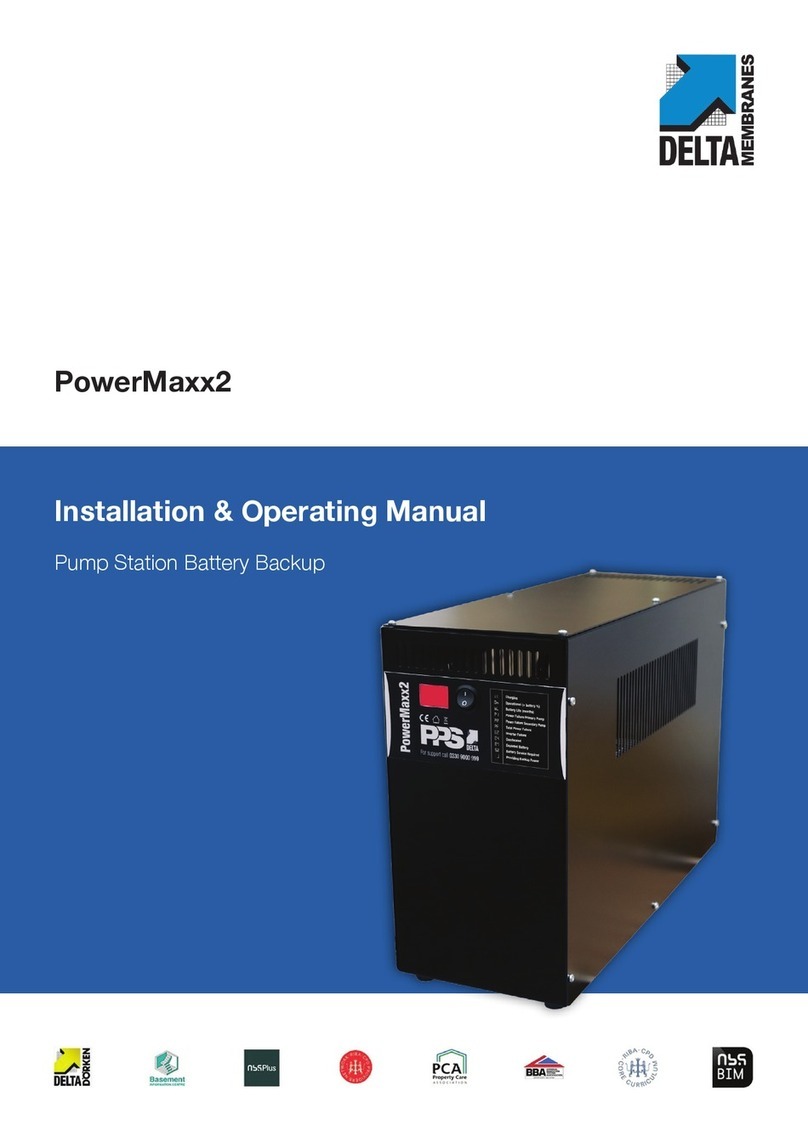
Delta Membranes Battery Backup User manual

INSTALLATION GUIDE
www.deltamembranes.com
INNOVATION | MANUFACTURER | DESIGN | SOLUTION
Delta Battery Backup

THIS MANUAL SHOULD BE KEPT WITH
THE PRODUCT OR THE HOMEOWNER

Contents
1. DeltaBatteryBackupoverview.......................................................................................................................................................... 1
1.1 DeltaBatteryBackupoverview................................................................................................................................................ 1
1.2 Keyfeatures............................................................................................................................................................................................ 1
1.3 Specication........................................................................................................................................................................................... 1
1.4 Associatedproducts......................................................................................................................................................................... 1
1.5 Remotemonitoring........................................................................................................................................................................... 1
1.6 Typicalinstallations.......................................................................................................................................................................... 3
1.7 Technicalspecications................................................................................................................................................................ 4
2. Safety ........................................................................................................................................................................................................... 5
3. Sitepreparation............................................................................................................................................................................................. 6
3.1 Advisory.................................................................................................................................................................................................... 6
3.2 Intendeduse......................................................................................................................................................................................... 6
3.3 Sitingtheproduct.............................................................................................................................................................................. 6
4. Installation.......................................................................................................................................................................................................... 6
4.1 ElectricalconnectionstotheDeltaBatteryBackup................................................................................................7
4.2 Wiringdiagram.................................................................................................................................................................................... 9
4.3 ConnectingahighlevelalarmminioattotheDeltaBatteryBackup...................................................10
4.4 ConnectingahighlevelalarmsumpoattotheDeltaBatteryBackup............................................... 12
4.5 ConnectingapumptotheDeltaBatteryBackup................................................................................................... 15
5. Operation.........................................................................................................................................................................................................16
5.1 Door-lockingisolatorswitch....................................................................................................................................................16
5.2 Switchingonthersttime........................................................................................................................................................16
5.3 Networkpowerfailure.................................................................................................................................................................16
5.4 Testfunction........................................................................................................................................................................................ 17
5.5 Serviceduereminders................................................................................................................................................................18
6. Alarms .........................................................................................................................................................................................................19
6.1 Highlevelalarm...............................................................................................................................................................................19
6.2 Nonetworkpoweralarm...........................................................................................................................................................19
6.3 Batteryfaultalarm..........................................................................................................................................................................19
6.4 Anomalyloadalarm......................................................................................................................................................................20
7. Remotemonitoring...................................................................................................................................................................................21
7.1 Volt-freecontacts............................................................................................................................................................................21
7.2 RS-485serialport........................................................................................................................................................................... 22
8. Maintenance................................................................................................................................................................................................. 23
8.1 Maintenanceoverview................................................................................................................................................................ 23
8.2 Batteries................................................................................................................................................................................................. 23
8.3 Spareparts........................................................................................................................................................................................... 23
9. Ancillaries........................................................................................................................................................................................................ 24
10. Declarations................................................................................................................................................................................................... 24
11. Warranty........................................................................................................................................................................................................ 25
12. Commissioningdetails.......................................................................................................................................................................... 26

1DMS_IG_DBB 0123Delta Battery Backup
1.DeltaBatteryBackupoverview
1.1 Delta Battery Backup overview
TheDelta BatteryBackupsystemwillautomatically provide
powertoone240Vsubmersiblepumpwhenthereisaloss
ofmainspower.
The Delta Battery Backup system will keep submersible
pumps running during this power outage, so that you can
continuetouseyourappliances.
Whilst reconnected to mains power the system will charge
andmaintainthebatteriestoensuretheyarealwaysready.
Simpletouseandeasytoinstall–DeltaBatteryBackupwill
clearlydisplaystatusandcomprehensivefaultcodes.
TheDeltaBatteryBackupisoeredinthreeranges:
• DeltaBatteryBackupV3–forDeltaV3pumps
• DeltaBatteryBackupV4/6–forDeltaV4/6pumps
• DeltaBatteryBackupFoulV3–forDeltaFoulV3pumps
Withintheseranges,therearestandard,PlusandXLmodels
whichprovideincreasinglevelsofbatteryautonomy.
1.2 Key features
• Capableofrunningonesubmersiblepumpwithoutmains
powerformorethan24hours
• Industryleadingbackuppower
• Includesahighlevelalarm
• Digitaldisplaytoshowstatusandfaultcodes
• Virtuallyinaudibleinnormaloperation
• Lockablesteelenclosure
• Door-lockingisolatorswitch
• Fourvolt-freecontactsforremotemonitoring
• RS-485seriallinecommunicationforremotemonitoring
• Periodicserviceduereminders
• Canberetrotted
1.3 Specication
• EuropeanDirective2006/95/CE
• ElectromagneticCompatibilityDirective2004/108/EC
• Andtheseharmonisedstandardsasapplicable:
EN61439-1,EN61439-2,EN60204-1,EN55014-1,
EN55014-2,EN61000-3-2,EN61000-3-3
1.4 Associated products
• DeltaDualV3
• DeltaDualV4
• DeltaDualV6
• DeltaFoulV3
• Delta800DualV3
• Delta800DualV4
• Delta800DualV6
• Delta800SingleFoulV3
The Delta Battery Backup is not suitable for Delta 800
DualFoulV3systems.PleasecontactDeltaMembranesfor
batterybackupoptionsforthesesystems.
1.5 Remote monitoring
Thesystemfeaturesfourvolt-freecontacts:
• Highlevelalarm
• Nonetworkpoweralarm
• Anomalyloadalarm
• Batteryfaultalarm
ThesystemalsofeaturesanRS-485serialport.
• Highlevelalarm
• Nonetworkpoweralarm
• Inverterfaultalarm
• Anomalyloadalarm
• Batteryfaultalarm
• Testfunction
TheRS-485interfacealsoprovidesa12Vcontacttopower
aremotecommunicationdeviceviatheserialline,should
itberequired.
Formoreinformation,pleaserefertoSection7.

01992523523inf[email protected]www.deltamembranes.com 2
1.DeltaHLAoverview
A
B
C
D
H
G
F
E
A Testbutton
B Resetbutton
C IP55steelenclosure
D 12Vbattery
E IlluminatedLCDdisplay
F Lock
G Doorlockingisolator
H Batteryholder
Figure 1. The Delta Battery Backup system.

3DMS_IG_DBB 0123Delta Battery Backup
1.DeltaHLAoverview
1.6 Typical installations
1.6.1 Dual pump systems
Mini oat switch Float shroud secured
with cable ties to pipework
Duty pump
(Delta V3 Pump)
Duty pump cable Backup pump cable
Backup pump
(Delta V3 Pump)
13 amp unswitched
fused spur
Suitably sized
breakers to be used
Volt-free contacts or
RS-485 serial link
(optional)
Distribution boardDelta Battery Backup V3
Float cable
1.6.1 Single pump systems
Suitably sized
breaker to be used
13 amp unswitched
fused spur
Foul V3 Submersible Pump
Float cable Pump cable
Counterweight
High level
alarm oat
Pump oat
Distribution board Delta Battery Backup Foul V3
RS-485 serial link
(optional)
Applicablepackagedpumpingstations:
• DeltaDualV3
• DeltaDualV4
• DeltaDualV6
• Delta800DualV3
• Delta800DualV4
• Delta800DualV6
ThisexampleshowsaDeltaBattery
BackupV3andDeltaDualV3
packagedpumpingstation.
TheBACKUPpumpshouldbepowered
viatheDeltaBatteryBackup.The
backuppumpswitchesonatahigher
levelthanthedutypump.
Applicablepackagedpumpingstations:
• DeltaFoulV3
• Delta800SingleFoulV3
ThisexampleshowsaDeltaBattery
BackupFoulV3andaDeltaFoulV3
packagedpumpingstation.
PleasecontactDeltaMembranesfor
batterybackupsystemsforDelta800
DualFoulV3packagedpumpingstations.
Figure 2. Typical installations for dual
pump systems.
Figure 3. Typical installations for single
pump systems.

01992523523inf[email protected]www.deltamembranes.com 4
1.DeltaHLAoverview
1.7 Technical specications
1.7.1 Control panel specications
Range V3 V4/6 Foul V3
Input
Nominalvoltage 230VAC
Nominalcurrent 9.7A
Breakersize RCBOType-C10A
Output
Outputvoltage 230VAC
Waveform 50Hzpuresinewave
Nominalcurrent 2A 6A 10A
Nominalpower 500W 1500W 2300W
Miscellaneous
Connectivity 4novolt-freecontacts,RS-485serialinterface
Ambienttemperature -5°Cto+40°C
Humidity <50%
Protection
Invertorprotectionfuse,
batterypolarityinversionprotection,
shortcircuitandoverloadprotection,
fusechargeprotection,
door-lockingisolator
Caseconstruction Metal,IP55
Security Lockingwithcodedkey
Weight 9kg(excl.batteries)
1.7.3 Battery capacities and autonomy
Model
V3 V4/6
Foul V3
Standard Plus XL Standard Plus XL
Battery type and
Numberofbatteries/holders 1 2 3 1 2 3 2
Batterytype 12V60Ah 12V100Ah 12V100Ah 12V100Ah 12V100Ah 12V100Ah 12V100Ah
DeltaV3
Intermittent* 60hours 120hours 240hours 90hours 120hours 240hours –
Continuous 60mins 120mins 240mins 90mins 120mins 240mins –
DeltaV4
Intermittent* – – – 55hours 105hours 170hours –
Continuous – – – 55mins 105mins 170mins –
DeltaV6
Intermittent* – – – 45hours 90hours 140hours –
Continuous – – – 45mins 90mins 140mins –
DeltaFoulV3
Intermittent* – – – – – – –
Continuous – – – – – – 30mins
*BasedonPCAguidanceof3activationsof20secondseachperhouranda3.5metrehead.Deviationfromtheseparameterswillchangethe
batteryautonomy.
For number of battery
compartments per model
please refer to the table below.
280 280 280
495
370
200
1.7.2 Dimensions

5DMS_IG_DBB 0123Delta Battery Backup
2.Safety
DANGER!
Do not wear metallic objects such as watches, rings, bracelets. May cause burns in the
event of a short-circuit between the battery poles.
DANGER!
Always assume the presence of 230 VAC 50 Hz mains power even in the event of a
mains power failure.
DANGER!
The batteries are sealed units and should not be opened. If battery acid comes into
contact with the eyes wash immediately and thoroughly with water. Seek medical help
immediately. Do not smoke, create sparks or use naked ames near the batteries.
WARNING!
Be careful not to short circuit the battery cables. Before making the connections, ensure
the cables are in good condition.
Strictlyfollowtheinstructionscontainedinthismanual.
WARNING!
For connection to the mains electrical supply it is imperative that the Delta HLA is
connected to a dedicated power supply and not via a ring main.

01992523523inf[email protected]www.deltamembranes.com 6
3.Sitepreparation
3.1 Advisory
Allproductsaremanufacturedanddevelopedtothehigheststandardsandassembledwithprecisionandcare.Eachproducthas
beenrigorouslytested.Weconstantlystrivetodevelopourproductstoprovideyouwiththemostinnovativeproductspossible.
Please read these installation and operating guidelines carefully prior to installation. These guidelines contain important
informationandhazardwarnings,whichwillenableyoutoinstallandoperateyourproductsafely,economically,andreliably.
OnlyqualiedpersonnelshouldcarryouttheinstallationinaccordancewiththelatestIETwiringregulationsBS7671.Allworks
shouldbeinlinewiththeHealthandSafetyatWorksAct1974.
Itisimportanttonotethattheseguidelinesareforguidanceonlyanditistheinstaller’sresponsibilitytosatisfythemselvesthat
theinstallationprocedureisinaccordancewithgoodpractice,thiswilltheneliminateanypotentialdamagetotheproductduring
orafterinstallation.
Ifyouareunsureonanypoint,thenpleasecontactDeltaMembraneson01992523523between8amand5pm,MondaytoFriday
orbyemailat[email protected]formoreinformation.
3.2 Intended use
DeltaBatteryBackupisdesignedforuseindooruseonly.Undernocircumstancesshouldtheproductbeinstalledoutdoors.
DonotoperatetheDeltaBatteryBackupindirectsunlight,incontactwithuids,orwherethereisexcessivedustorhumidity.
Allowadequatespaceforproperventilation.
Theoutputpowercanbesetbyselectingtheinvertersize.Inchoosingthis,itisadvisabletoexceedtheratedpowerofthepump
by30%.Forexampleifthepumpis500W,settheoutputpowerto750W.
3.3 Siting the product
SelectasuitablelocationfortheDeltaBatteryBackup,takingintoaccountcablelengthsfromthebaseofthepumpchamber/
sump,throughthecableducttothepanel.Ifyouneedtomountthepanelfurtherawayfromthepumpchamber/sump,please
contactDeltaMembraneson01992523523between8amand5pm,MondaytoFridayorbyemailatinfo@deltamembranes.
comformoreinformation.
Installtheequipmentinadryandwell-ventilatedplaceandaccessiblebytheenduserandserviceengineers.
Itmustbelocatedwherethepanel’salarmisaudible.PleaseconsidertheNoisePollutionAct.
Theequipmentshouldbexedtothewallaminimumof500mmaboveFFL.Thebatteryholder(s)musttobexedtotheDelta
BatteryBackupenclosureaswellastothewall.
2.Sitepreparationandinstallation

7DMS_IG_DBB 0123Delta Battery Backup
4.1 Electrical connections to the Delta Battery Backup
• TheDeltaBatteryBackupshouldbeconnectedtoadedicatedRCBOType-C10Abreakeratthemainsdistributionboard.
• Theequipmentmustbeinstalledbyqualiedpersonnel
• Theconnectionsmustbemadeintheabsenceofvoltage
• Usetoolswithaninsulatinghandle
• Respectthephase-neutralconnectionsandtheindicatedpolarities.Damagesduetonon-compliancewiththiswarningare
notbecoveredbythemanufacturer’swarranty
• Thecableglands(supplied)mustbepassedoverbothcontainers(equipment/batterycompartment)
4.1.1 Wiring schematic for dual pump installations
4.Installation
Mini oat switch Float shroud secured
with cable ties to pipework
Duty pump
(Delta V3 Pump)
Duty pump cable Backup pump cable
Backup pump
(Delta V3 Pump)
13 amp unswitched
fused spur
Suitably sized
breakers to be used
Volt-free contacts or
RS-485 serial link
(optional)
Distribution boardDelta Battery Backup V3
Float cable
A B
Breaker specication
Description Device type Rating
ASubmersiblepump RCBO,TypeC Bypump*
BDeltaBatteryBackup RCBO,TypeC 10A
*Pleaserefertothepumpingsysteminstallation
guideforRCBOratingforeachpumptype.
Figure 4. Wiring schematic for dual pump installations.

01992523523inf[email protected]www.deltamembranes.com 8
4.Installation
Suitably sized
breaker to be used
13 amp unswitched
fused spur
Foul V3 Submersible Pump
Float cable Pump cable
Counterweight
High level
alarm oat
Pump oat
Distribution board Delta Battery Backup Foul V3
RS-485 serial link
(optional)
A
Breaker specication
Description Device type Rating
ADeltaBatteryBackup RCBO,TypeC 10A
4.1.2 Wiring schematic for single pump installations
Figure 5. Wiring schematic for single pump installations.

9DMS_IG_DBB 0123Delta Battery Backup
F1
BATTERY
CHARGER
FUSES
BATTERY
CHARGER
INVERTER
FUSE
ARRAY
12 V BATTERY
BATTERY CHARGER
EARTH 230 VAC 50/60 Hz ± 5%
1
0
INPUT INVERTER
AUTOMATIC PUMP POWER
(DIRECT LOAD)
MANUAL PUMP POWER
(AUX LOAD)
12 VDC BATTERY
MANUAL PUMP FLOAT
(AUX CONTACT)
INVERTER ON/OFF
LNL
NL
NL
NIL IN ULM.LEV UN
HIGH LEVEL FLOAT
(MAX LEVEL CONTACT)
AL AN
4.2 Wiring diagram
Figure 6. Delta Battery Backup wiring diagram.
4.Installation

4.3 Connecting a high level alarm mini oat to the Delta Battery Backup
4.3.1 Mounting a high level alarm mini oat (Delta Dual V3/V4/V6)
Pleaserefertothespecicinstallationandoperatingguidelinesforthechamber/sumpwheninstallingtheoatswitch.
The mini oat switch is suppliedwith a 5 m cable. Ifyou require more than 5 metres please contact Delta Membranes on
01992523523between8amand5pm,MondaytoFridayorbyemailat[email protected]forassistance.
1. Theminioatswitchshouldbepositionedbetweentheactivationpointsofthetwopumps,asshowninFigure7.Thiswill
causethealarmtotriggerifPump1hasfailed,beforePump2emptiesthechamber.Thisperiodictriggeringisauseful
indicatorthatthereisafaultinthepumpingstation.
2. Theminioatswitchshouldbeinstalledintheoatshroud.Theoatshroudshouldbepositionedontheverticalpipework
oftherearpumpsothatitbuttsuptothebaseoftheelbowandsecuredwithcableties.SeeFigure8.
3. Whenpositioningtheminioatswitchinserttheoatcablethroughthegreenwasher.
4. PlacetheminioatswitchintopositionwiththeactivationarmlocatedinthedownwardspositionasshowninFigure9.
5. Inserttheminioatcablethroughtheblueplasticwasherandnutandtightenfully.
6. Cabletobedrawnthroughcableductbetweenthechamber/sumpandcontrolpanellocationforremovalatalaterdate.
Figure 7. Mini oat switch on and o positions.
Figure 8. Fixing and orienting the oat shroud.
HLA ON
HLA OFF
PUMP 2 START
PUMP 1 START PUMP 2 STOP
PUMP 1 STOP
Orient the oat shroud so
that it does not interfere
with the pumps’oat arms
Fix the oat shroud to
the vertical pipework
with two cable ties
4.Installation

11 DMS_IG_DBB 0123Delta Battery Backup
ON
OFF
Figure 9. Mini oat switch OFF and ON positions.
4.3.2 Connecting a high level alarm mini oat to the Delta Battery Backup
1. LoosentheoatswitchcableglandlocatedontheundersideoftheDeltaBatteryBackup.
2. Drawtheminioatswitchcablethroughthecablegland.
3. ConnectthebrowncoretothepositiveandthebluecoretothenegativeterminaloftheHighLevelFloat(M.LEV)terminal.
Figure 10. Connecting the mini oat switch to the Delta Battery Backup.
L N L N IL IN ULM.LEV UN AL AN
MINI FLOAT SWITCH
4.Installation

01992523523inf[email protected]www.deltamembranes.com 12
4.4 Connecting a high level alarm sump oat to the Delta Battery Backup
4.4.1 Mounting a high level alarm sump oat (Delta Foul V3, Delta 800 Series)
Pleaserefertothespecicinstallationandoperatingguidelinesforthechamber/sumpwheninstallingtheoatswitch.
Thesump oat switchis suppliedwith a 10mcable.Shouldyourequiremorethan10metrescontactDeltaMembraneson
01992523523between8amand5pm,MondaytoFridayorbyemailat[email protected]forassistance.
1. Pleaseensureyoupositionthesumpoatswitchhigherthantheprimarypumpactivationpointcontainedwithin,asshown
inFigure11,12or13.
2. Installthesumpoatswitchcablesecurely.Thesumpoatswitchshouldbeinstalledusingaoatbracket.TheDeltaFoul
V3chamberfeaturesanintegraloatbracket.800Serieschambersfeatureasteeloatbracket.
3. Attachthecounterweightapproximately70mmfromthetopoftheoatswitch.Youmustseparatethecounterweight
byremovingthecentrescrewusinga6mmAllenkey,onceseparatedyouwillseetwogrooves,usingthesmallerofthe
groovespositionthecableintoplaceandputthecounterweightbacktogetherensuringthecentrescrewistightened.
4. PulltheoatcablethroughtheM20cableglandontheoatbracket.Positionthesumpoatswitchhigherthanthe
primarypumpactivationpoint.OncetheoathasbeenpositionedtightentheM20gland.
5. Fixthecableintopositionusingacabletietoensuretheoatdoesn’tdropdown.
6. Cabletobedrawnthroughcableductbetweenthechamber/sumpandcontrolpanellocationforremovalatalaterdate.
Delta Foul V3
Packaged Pumping Stations
Counterweight
Float bracket
Cable tie to secure the
oat at the correct height
HLA ON
HLA OFF
PUMP START
PUMP STOP
Figure 11. Setting the switching heights of the sump oat in a Delta Foul V3 Packaged Pumping Station.
4.Installation

13 DMS_IG_DBB 0123Delta Battery Backup
Figure 12. Setting the switching heights of the sump oat in a Delta Dual V3/V4/V6 800 Series Packaged Pumping Station.
Figure 13. Setting the switching heights of the sump oat in a Delta Single V3 Foul 800 Series Packaged Pumping Station.
HLA ON
HLA OFF
PUMP 1 START
PUMP 1 STOP
PUMP 2 START
PUMP 2 STOP
Float cable secured
to bracket with 20 mm
cable gland and cable tie.
Counterweight
HLA ON
HLA OFF
PUMP 1 START
PUMP 1 STOP
Float cable secured
to bracket with 20 mm
cable gland and cable tie.
Counterweight
4.Installation

4.4.2 Connecting a high level alarm sump oat to the Delta Battery Backup
1. LoosentheoatswitchcableglandlocatedontheundersideoftheDeltaBatteryBackuppanel.
2. Drawthesumpoatswitchcablethroughthecablegland.
3. Connectthebrowncoretopositiveandtheblackcoretothenegativeterminal,asshowninFigure14.
4. Ensurethatthebluecoreisisolated.
Figure 14. Connecting the sump oat to the Delta Battery Backup.
L N L N IL IN ULM.LEV UN AL AN
SUMP FLOAT SWITCH
BLUE CORE TO BE ISOLATED
4.Installation

15 DMS_IG_DBB 0123Delta Battery Backup
4.5 Connecting a pump to the Delta Battery Backup
L N L N IL IN ULM.LEV UN AL AN
AUTOMATIC PUMP
L N L N IL IN ULM.LEV UN AL AN
SUMP FLOAT
SWITCH
MANUAL
PUMP
BLUE CORE TO
BE ISOLATED
Figure 16. Connecting a manual pump to the Delta Battery Backup.
Figure 15. Connecting an automatic pump to the Delta Battery Backup.
4.5.2 Connecting a manual pump to the Delta Battery Backup
4.5.1 Connecting an automatic pump to the Delta Battery Backup
Shouldyouneedtoconnecta
manualpumptotheDeltaBattery
Backup,usetheAL/AN(Aux
Load)terminalsinsteadofthe
UL/UN(DirectLoad)terminals.
Thelevelcontrol(oat,pressure
switchetc)whichcontrolsthe
pumpshouldconnecttotheAux
Contactterminals.
WhentheAuxContactterminals
areclosedbytheactivatedlevel
control,avoltageisapplied
acrosstheAL/ANterminalsthus
poweringthepump.Whenthe
levelcontroldeactivates,theAux
Contactisopenedandthepump
isde-powered.
AllstandardDeltapackaged
pumpingstationsthatare
compatiblewiththeDeltaBattery
Backupfeatureautomaticpumps
(pumpswhichcomewithaoat
alreadyattached).
• DeltaV3Pump
• DeltaV4Pump
• DeltaV6Pump
• DeltaFoulV3Pump(Automatic)
TheseconnecttotheUL/UN
(DirectLoad)terminals.
Inoperation,therewillalwaysbe
avoltageacrosstheseterminals.
Thepump’sintegraloatswitchwill
activatethepump.
4.Installation

01992523523inf[email protected]www.deltamembranes.com 16
5.1 Door-locking isolator switch
Thesystemisprotectedbyadoor-lockingisolatorswitch.ToopenthedoorItmustbeintheOFFposition.
5.2 Switching on the rst time
Afterinstallation,closethedoorandturntheisolatortotheONposition.
Assumingthereismainspower,thedisplaywillread“NETWORKPRESENCE”.
5.Operation
WhiletheDeltaBatteryBackupisconnectedtomainspoweritwillchargeandmaintainthebattery(s).After15minutes,itwill
carryouttherstreadingofthebatteryvoltageanddisplayit..
Thebatteryvoltagereadingisupdatedeverytwohours.
5.3 Network power failure
IntheeventofnetworkpowerfailuretheDeltaBatteryBackupautomaticallydisconnectsthebatterychargerandswitchesto
poweringthepumpfromthebatteryviatheinverter.Thedisplaywillread“NONETWORKPRESENCE“.
Thesystemcontinuestopowerthepumpuntiltheinputvoltagefromthebatterydropsbelow10VDC,afterwhichthesystemis
placedinSTANDBY.

17 DMS_IG_DBB 0123Delta Battery Backup
5.4 Test function
Inthe“NETWORKPRESENCE”state,pressingthe“TEST”buttonwillcarryoutthefollowingoperations:
• disconnectsofthebatterycharger
• switchesformmainspowertobatterypowerviatheinverter
• powerstheAuxiliaryLoadterminal
Ifafter30secondsnoanomalieshavebeendetectedintheconnectedloadorintheinverter,thedevicewillreturntonormal
functionwithoutanycommunication.
Ifananomalyisdetected,theappliancewillmake5resetattemptsand,ifallattemptsfail,thesystemwilltriggeranAnomaly
Loadalarm(K6relay)andthescreenwilldisplay“ANOMALYLOAD”.
ToresetthesystempresstheRESETbutton.
WARNING!
The unit must be tested with both mains power connected and disconnected.
5.Operation
This manual suits for next models
6
Table of contents
Other Delta Membranes Camera Accessories manuals
