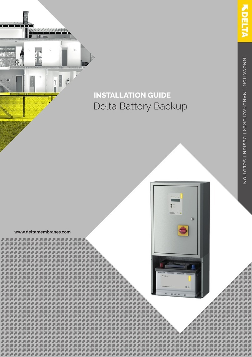
Delta Membranes PowerMaxx2 Installation instructions

Installation & Operating Manual
Pump Station Battery Backup
PowerMaxx2

PMX2-M-V1-02.20
Legal information/Copyright
All rights reserved. Contents provided herein must neither be distributed, copied, reproduced, edited or
processed for any other purpose, nor otherwise transmitted, published or made available to a third party without
express written consent from Delta Membranes.
Subject to technical modication without prior notice.
© Delta Membranes 2020
Delta House, Merlin Way, North Weald, Epping, Essex. CM16 6HR
01992 523 523
www.deltamembranes.com
T.
E.
W.

3
Contents
1.0 PowerMaxx2 overview 4
2.0 Box contents 4
3.0 Technical information 4
4.0 Health & Safety 5
5.0 Unit location 5
6.0 Safety 5
7.0 General 6
8.0 Wiring schematic 6
9.0 Wiring a standalone PowerMaxx2 7
10.0 Conguring the upper circuit board to the pump/s & alarm 8
11.0 Setup and conguration of the unit 9
12.0 Principals of operation 10
13.0 Battery life & servicing 10
14.0 Connecting an AlertMaxx2 or Rego1 (if purchased) 11
15.0 MaxxConnect cabling 11
16.0 AlertMaxx2 wiring schematic 12
17.0 Wiring a MaxxConnect system 13
18.0 Additional error codes 13
19.0 Spares 13
20.0 Error codes (PowerMaxx2) 14
21.0 U-Menu 15
22.0 Inverter check 15
23.0 Guarantee 15
24.0 PPS Technical Department 15

1.0 PowerMaxx2 overview
2.0 Box contents
3.0 Technical information
PowerMaxx2 (DMS-280-1) contents
• 1 x PowerMaxx2 Unit - Battery supplied internally, but disconnected on delivery
• Gland Pack (4 x Large Cable Glands, 2 x Large Blanking Plugs, 1 x Small Cable Gland, 1 x Small Blanking
Plug, 4 x Large Nuts & 1 x Small Nut)
• 1 x 3m length of MaxxConnect family cable
• 1 x Installation & Operating Instructions (this document)
• 1 x Chamber Location Sticker Sheet (for Spurs)
The PowerMaxx2 is designed to provide battery backup to pump stations in the event of a mains failure.
They have been specically designed to meet the requirements of the pump industry. The PowerMaxx2 has the
ability to connect to the AlertMaxx2 high level alarm and Rego1 control panel.
Specication
Size W: 155mm x D: 425mm x H: 300mm
Weight inc. battery 19kg
Mains supply 200-250V AC (50Hz)
Internal battery 24V - 1x22Ah VRLA
Power - charging 75W
Power - idle <3W
Visual display 2 x seven segment
Operating temperature 5-35°C
Ideal operating temperature 20-25°C
Humidity range <80% RH
Approximate Installation time 60 minutes
Feeds 1 or 2 (13A non-switched)
Devices (pump/s) 1 or 2 (cannot provide together)
IP Rating IP2X
4

5
4.0 Health & Safety
In order to minimise the risk of ill health or accidents when installing and/or servicing pump chambers and
associated accessories, workers must be fully trained and competent. The following guidelines will help
safeguard matters:
• Assessing the risk and working in accordance with the control measures identied.
• Ensure electrical power to the equipment is isolated before carrying out installation or maintenance.
• A suitable rst aid kit must be close to hand.
• The electrical installation must comply with the requirements of BS 7671:2008 ‘Requirements for Electrical
Installations’ incorporating amendment 3:2015.
5.0 Unit location
CAUTION!
The unit is IP2X and is not waterproof, it must be installed indoors or inside a kiosk. The unit must
also be installed in a chemically neutral environment with a relative humidity of <80% and a maximum
temperature of 35°C. It is recommended that the unit is installed o the oor.
Installations not following this guidance will void the manufacturer’s guarantee.
The unit must be positioned where there is sucient air circulation to all the vents and is permanently accessible
for servicing. If using in conjunction with an AlertMaxx2 high level alarm or Rego1, please ensure the units are no
further than a 20m cable length from each other.
MaxxConnect cable can be purchased per 10m (DMS-288). Do not join cables. Run full lengths only.
CAUTION!
This product should only be installed by qualied personnel in accordance with the latest regulations.
Battery Type: Lead-acid
Battery Specification: 24V DC 22Ah
Caution: Replace with same type only
Risk of electric shock & chemical hazard.
Refer to the instruction manual for handling,
disposal & maintenance information.
6.0 Safety
The unit has 240V present at all times and can generate dangerous voltage even if the mains supply is
cut. The black power switch only disables the ability to generate 240V from the battery pack; however, mains
feeds are still live and present supplying the pumps. To be completely safe, remove the fuses from both spurs,
ensure the unit is switched o and disconnect the battery pack.

6
The PowerMaxx2 can supply one or two pumps (not simultaneously) and have been certied for use on:
• V3
The supplies to the pump/s should be separately fused using non-switched fused spurs and not on
the same ring mains.
7.0 General
8.0 Wiring schematic
Figure 1. Wiring schematic
- The pump is supplied with a 10m cable.
- When only using the standard 10m
cable attached to the pump, the cable
duct should be no longer than 6m.
- If the cable duct requires to be longer
than 6m, please follow the cable
extension guide to select an appropriate
cable core diameter.
The electrical installation must comply with the requirements of
BS 7671:2008 ‘Requirements for
Electrical Installations’ incorporating amendment 3:2015
Separate 16 Amp RCBO’s
13 Amp Non-switched
fused spurs
Secondary
From Mains
Primary
From Mains
Primary To Pump
Secondary To Pump
PRIMARYSECONDARY
The below wiring schematic shows a typical installation using a PowerMaxx2 and Dual V3 pump station.

7
9.0 Wiring a standalone PowerMaxx2
1. Remove the fuses from the spurs that will power the pumps being used with the PowerMaxx2.
2. Ensure the power switch of the PowerMaxx2 is in the OFF position.
3. Remove the PowerMaxx2 lid and side panels from the unit.
4. If you are conguring the unit with one pump, t two large cable glands into the primary side of the unit
and two blanking plugs into the secondary side of the unit.
If you are conguring the unit with two pumps, t two large cable glands into the primary side of the unit
and two large cable glands into the secondary side of the unit.
If you are connecting an AlertMaxx2, t a small cable gland into the small hole above the secondary holes.
5. Using the cable glands on the back of the PowerMaxx2, feed the power and pump cables through and to
the correct terminal blocks on the lower circuit board.
There are two connector blocks on the lower circuit board: PRIMARY and SECONDARY. The primary
connector block should always have a connection, as this is the supply that charges the PowerMaxx2.
6. Connect the supply to the “From Mains” and the corresponding pump to the “To Pump” (gure 2).
7. Connect the battery pack by plugging in the grey Anderson connector.
Primary Pump
Secondary Pump
From MainsTo Pump
L N E E N L
L N E E N L
To PumpFrom Mains
To Front of Unit
Figure 2. Wiring the lower circuit board - PowerMaxx2

8
10.0 Conguringtheuppercircuitboardtothepump/s&alarm
1. Using the diagram below, set the switches on the upper circuit board according to your systems
conguration (gure 3).
2 Pumps1 PumpAlarmNo Alarm
Figure 3. Conguring the upper circuit board - PowerMaxx2

9
11.0 Setupandcongurationoftheunit
1. Replace the side panels of the unit, followed by the lid.
2. Replace the fuses to the spurs supplying the unit and turn on the mains power.
3. Check that the pump/s are receiving power (withtheunitswitchedo) by lifting the oat switches on
the pump/s.
4. Switch the unit on; the screen will display a left to right start sequence, followed by the software release.
5. A C0 will show on the display while the unit checks the environment and the connections. C0 will be present
for approximately 10-15 seconds.
6. If the unit passes the initial cong, a CC will be shown on the display and then the unit will restart and show
-- followed by On and then ip between the charging bars and the -- while the unit calculates the battery
percentage (this can take up to 3 minutes). Once the unit has calculated the battery percent, it will
stop displaying -- and show a gure from 0-99% depending on the state of the battery.
7. If the unit fails to congure correctly (error code below) - switch the unit o, remove the fuses from the spurs,
remove the side panels and lid, redo the connections or set the conguration switches to the correct
positions and then replace the covers and turn the unit back on. If the issue still persists, please call
technical support on 0330 9000 999.
8. If you are connecting an AlertMaxx2 or Rego, please refer to section 14.0 of this manual.
Code Duringinitialconguration
C0 Cong started.
C1 No primary mains present. Check supply.
C2 No secondary mains present. Check supply.
C3 No battery connected. Connect battery.
C4 Primary mains ‘in’ and pump ‘out’ swapped. Swap over wiring.
C5 Secondary mains ‘in’ and pump ‘out’ swapped. Swap over wiring.
C6 Pump switch in ‘1P’, but 2 mains ‘in’ detected. Change switch to correct setting.

12.0 Principals of operation
Normal operation
In normal operation, the power bypasses the unit which acts as a junction box, and this then feeds the pumps
directly. Pump supply #1 (primary) also charges the battery.
Backup operation
When the unit senses that the power is down, the unit enters backup mode. To save power, the battery backup
will periodically and dynamically test if the pump/s need power (oat up) using a system called DyPol (from
10-180 seconds depending on how often the pumps are cycling). If the pump/s need power, it will serve the
pump requesting power for as long as needed or until the battery is depleted.
If two pumps are connected and both supplies have failed it will serve both pumps in a rotational manner giving
equal priority until the power returns or the battery backup is depleted.
If the secondary power has failed, it will serve the secondary pump as required from the battery. However, it will
also charge the battery from the primary spur, when the secondary pump does not need power.
Charging
After any power failure, the battery is always charged. The battery is also charged and topped up every 21 days.
This process can take up to 5 hours for a PowerMaxx2 to fully charge an empty battery.
13.0 Battery life & servicing
The battery has a nominal life span of 3 years and is displayed on the unit with a bL+%. This life span is
shortened over time and also by the following:
• Temperatures above 25°C.
• The number of discharges (the number of times the unit has been used without mains power).
• The depletion level when discharging and the number of times the batteries are used. Extended periods
providing backup power will impact battery life.
Replacement of the battery pack should be done every 2-3 years to ensure the maximum backup time. In some
cases, the battery may need earlier replacement. This will be indicated by an S2 on the PowerMaxx2.
Servicing of the battery pack should be performed by a qualied service person with knowledge about batteries
and the required precautions. The battery pack should be replaced with the same type the unit is installed with.
This information can be found within the unit or on page 5.
WARNING!
Do not dispose of batteries in a re. The batteries may explode.
Do not dispose of batteries in landll. Please recycle safely at your local recycling plant.
Do not open or damage batteries. Released electrolyte is harmful to the skin and eyes and may be toxic.
• To reset the S2, see section 21.0 - U6.
Please note, the battery service reset should only be performed by qualied personnel and only when the battery
has been changed. It is the owner’s responsibility to ensure the battery is replaced when required. If the battery
is not change when needed, the unit will not be able to backup the pumps according to the specication and in
some instances, not at all.

14.0 Connecting an AlertMaxx2 or Rego1 (if purchased)
PLEASE NOTE
The AlertMaxx2 must have the pump/s wired into it. The AlertMaxx2 must be installed in series to
the PowerMaxx2, this means the AlertMaxx2 must be installed in between the PowerMaxx2 & the
pump/saspergure5onpage12.
The PowerMaxx2 can be connected to an AlertMaxx2 or Rego1. Battery backup capacity and condition are fed
directly to the SideWinder Tech software when connected to the internet.
The PowerMaxx2 is supplied with 3m of 4 core MaxxConnect family cable.
15.0 MaxxConnect cabling
The units are to be a maximum of 20m cable distance apart. MaxxConnect family cable can be purchased per
10m (DMS-288). Do not join cables. Run full lengths only.
Figure 4. Wiring diagram
4.
3.
2.
1.
5.
Mamba GW Wiring Label - [MGWW-LB-V3-06.17].pdf 1 07/06/2017 16:19
11

16.0 AlertMaxx2 wiring schematic
Figure 5. AlertMaxx2 wiring schematic
PRIMARYSECONDARY
AlertMaxx2 High Level Alarm
(DMS-298)
For internal wiring of the high
level alarm, please refer to the
AlertMaxx2 instruction manual.
- The pump is supplied with a 10m cable.
- When only using the standard 10m
cable attached to the pump, the cable
duct should be no longer than 6m.
- If the cable duct requires to be longer
than 6m, please follow the cable
extension guide to select an appropriate
cable core diameter.
Finger Float Switch
The electrical installation must comply with the requirements of
BS 7671:2008 ‘Requirements for
Electrical Installations’ incorporating amendment 3:2015
Separate 16 Amp RCBO’s
13 Amp Non-switched
fused spurs
Secondary
From Mains
Primary
From Mains
Primary To Pump/
AMX2 Mains In
Secondary To Pump/
AMX2 Mains In
MaxxConnect Cable
PowerMaxx2 Battery Backup
(DMS-280-1)
For internal wiring of the battery
backup, please refer to the
PowerMaxx instruction manual.
12

17.0 Wiring a MaxxConnect system
1. Install the AlertMaxx2 or Rego1 and battery backup as per the wiring schematic on page 12.
Leaveisolatedandturnedo.
2. Wire in the MaxxConnect cable according to the wiring schematic on page 12.
3. Congure the switches are per section 10.0.
4. Reconnect the batteries in the battery backup and AlertMaxx2/Rego1.
5. Ret the fascia/covers and power on the mains and units.
6. The battery backup should now startup with a ashing decimal dot indicating it is trying to nd the
AlertMaxx2/Rego1. This could take up to 2 minutes to clear.
CAUTION!
MaxxConnect misconnections will destroy one or all connected units (this can be detected by the
manufacturer) and void the guarantee.
The MaxxConnect introduces two new error codes to the PowerMaxx2 and one new error code to the
AlertMaxx2/Rego1:
1. PowerMaxx2 - ashing decimal dot - Trying to nd the AlertMaxx2/Rego1
2. PowerMaxx2 - E5 - Cannot nd the AlertMaxx2/Rego1
3. AlertMaxx2/Rego1 - E5 - Cannot nd battery backup
If the mains power fails, the AlertMaxx2 and Rego1 will keep themselves operating and charging from the battery
backup. Please note, this will reduce the resilience of the battery backup.
18.0 Additional error codes
Part No. Description
DMS-366 24V Battery Pack
DMS-288 MaxxConnect family cable extension - sold per 10m
19.0 Spares
13

14
Code Fault
E2 Inverter failure. Call support 0330 9000 999.
E3 Charger error. Call support 0330 9000 999.
E4 Overheated. The unit is exposed to temperatures above 35℃.
E5 Cannot detect an AlertMaxx2 or Rego1. Can be intermittent, will usually resolve.
E7 Depleted battery or disconnected. Activate mains power or connect the battery.
E8 Serious software error. Call support 0330 9000 999.
EE Empty U-menu slot
S2 Battery replacement required. Call support 0330 9000 999.
P1 + % Power failure on primary pump + battery %
P2 + % Power failure on secondary pump + battery %
PF + % Total power failure + battery %
On+%+bL+month Unit operational + battery % + battery life in months (normal operation)
--
--
--
Unit charging + battery %
Snake pattern Unit providing power to pump (only shown during power failure and providing)
20.0 Error codes

15
22.0 PPS Technical Department
If you are experiencing any technical issues, please contact the PPS Technical Department on 0300 9000 999
from 9:00am - 5:00pm or email info@ppsgroupuk.com.
23.0 Guarantee
The PowerMaxx2 is oered with a 24 month component guarantee. This guarantee only covers any defects in
workmanship, construction or material. This guarantee does not cover, defects caused by incorrect installation,
installer error, abnormal working conditions, misuse or neglect.
U-Menu Slot Function
U1 Shows the live running current of each connected pump. Press again to clear or will time
out automatically and clear.
U5 Shows the total backup time that the PowerMaxx2 has provided backup power (showing
in minutes). Press again to clear or will time out automatically and clear.
U6 Used to reset the S2 battery indicator back to 3 years (36 months). After releasing on U6,
bL will show on the display. Press and hold the button until OH appears on the screen,
the OH will clear and the unit will display On or the charging bars.
21.0 U-Menu
The PowerMaxx2 has a number of service routines (U-Menu) which can be used for various functions (as detailed
below). The U-Menu can be accessed by pressing and holding the button at the top of the upper PCB. Release
the button on the chosen U-Menu slot.
PLEASE NOTE
The upper PCB is capable of producing 12V. Ensure you only press the button.
22.0 Inverter check
The inverter in the PowerMaxx2 will initiate a self-check after the initial cong stage and then periodically. This is
implemented in the software to ensure the inverter res up correctly and will provide power to the pump when
needed.

Delta Membranes Ltd.
Delta House, Merlin Way, North Weald, Epping, Essex. CM16 6HR
01992 523 523
www.deltamembranes.com
T.
E.
W.
Table of contents
Other Delta Membranes Camera Accessories manuals
