manuals.online logo
Brands
  1. Home
  2. •
  3. Brands
  4. •
  5. Graco
  6. •
  7. Water Pump
  8. •
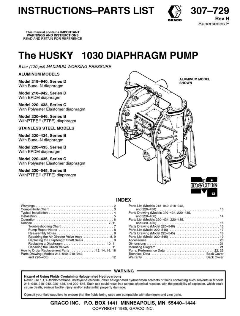
  9. Graco 225014 Operation manual

Graco 225014 Operation manual

This manual suits for next models

17

Other Graco Water Pump manuals

Graco 207321 Operation manual

Graco

Graco 207321 Operation manual

Graco Dyna-Star 26A938 User manual

Graco

Graco Dyna-Star 26A938 User manual

Graco 12 VDC EGP User manual

Graco

Graco 12 VDC EGP User manual

Graco Husky 715 Operation manual

Graco

Graco Husky 715 Operation manual

Graco 224342 A Series User manual

Graco

Graco 224342 A Series User manual

Graco 29:1 Lube Pro User manual

Graco

Graco 29:1 Lube Pro User manual

Graco ProMix PD2K User manual

Graco

Graco ProMix PD2K User manual

Graco Merkur A Series Parts list manual

Graco

Graco Merkur A Series Parts list manual

Graco HIGH-FLO 243737 User manual

Graco

Graco HIGH-FLO 243737 User manual

Graco VISCOUNT II 210-107 Operation manual

Graco

Graco VISCOUNT II 210-107 Operation manual

Graco Husky 1040 Operation manual

Graco

Graco Husky 1040 Operation manual

Graco Python A25177 User manual

Graco

Graco Python A25177 User manual

Graco 239923 Operation manual

Graco

Graco 239923 Operation manual

Graco QUANTM i30 User manual

Graco

Graco QUANTM i30 User manual

Graco 203872 Operation manual

Graco

Graco 203872 Operation manual

Graco G3 Pro User manual

Graco

Graco G3 Pro User manual

Graco G3 Series User manual

Graco

Graco G3 Series User manual

Graco Series A Operation manual

Graco

Graco Series A Operation manual

Graco Husky 2200 Use and care manual

Graco

Graco Husky 2200 Use and care manual

Graco ProConnect 19Y298 Operating instructions

Graco

Graco ProConnect 19Y298 Operating instructions

Graco E-Flo SP EC100CS2 User manual

Graco

Graco E-Flo SP EC100CS2 User manual

Graco SaniForce 24E836 Parts list manual

Graco

Graco SaniForce 24E836 Parts list manual

Graco Husky 1050 Series User manual

Graco

Graco Husky 1050 Series User manual

Graco T2 User manual

Graco

Graco T2 User manual

Popular Water Pump manuals by other brands

Watershed Innovations HYDRAPUMP SMART FLEX Instructional manual

Watershed Innovations

Watershed Innovations HYDRAPUMP SMART FLEX Instructional manual

Messner MultiSystem MPF 3000 operating instructions

Messner

Messner MultiSystem MPF 3000 operating instructions

Xylem Bell & Gossett WEHT0311M Installation, operation and maintenance instructions

Xylem

Xylem Bell & Gossett WEHT0311M Installation, operation and maintenance instructions

WilTec 50739 Operation manual

WilTec

WilTec 50739 Operation manual

Franklin Electric Little Giant 555702 HRK-360S instruction sheet

Franklin Electric

Franklin Electric Little Giant 555702 HRK-360S instruction sheet

Ingersoll-Rand PD02P Series Operator's manual

Ingersoll-Rand

Ingersoll-Rand PD02P Series Operator's manual

VS ZJ Series Operating	 instruction

VS

VS ZJ Series Operating instruction

Flotec FPZS50RP owner's manual

Flotec

Flotec FPZS50RP owner's manual

SKF Lincoln FlowMaster II User and maintenance instructions

SKF

SKF Lincoln FlowMaster II User and maintenance instructions

Xylem Lowara LSB Series Installation, operation and maintenance instructions

Xylem

Xylem Lowara LSB Series Installation, operation and maintenance instructions

Water Duro Pumps DCJ500 Operating & installation instructions

Water

Water Duro Pumps DCJ500 Operating & installation instructions

Action P490 Operating instructions & parts manual

Action

Action P490 Operating instructions & parts manual

Flo King Permacore Reusable Carbon Bag Disassembly. & Cleaning Instructions

Flo King

Flo King Permacore Reusable Carbon Bag Disassembly. & Cleaning Instructions

ARO ARO PD15P-X Operator's manual

ARO

ARO ARO PD15P-X Operator's manual

Pumptec 112V Series Operating instructions and parts manual

Pumptec

Pumptec 112V Series Operating instructions and parts manual

Virax 262070 user manual

Virax

Virax 262070 user manual

Neptun NPHW 5500 operating instructions

Neptun

Neptun NPHW 5500 operating instructions

Sensidyne Gilian BDX-II Operation & service manual

Sensidyne

Sensidyne Gilian BDX-II Operation & service manual

manuals.online logo
manuals.online logoBrands
  • About & Mission
  • Contact us
  • Privacy Policy
  • Terms and Conditions

Copyright 2025 Manuals.Online. All Rights Reserved.

307880
Rev. E
Supersedes Rev. D
First choice when
quality counts.
t
INSTRUCTIONS–PARTS LIST
INSTRUCTIONS
This manual contains important
warnings and information.
READ AND KEEP FOR REFERENCE.
Fire-BallRand PresidentR
Lubrication Pumps
Stationary Installations and Mobile Units for Heavy Grease
15:1 Ratio Fire-Ball Pumps: 2700 psi (19 MPa, 186 bar) Maximum Working Pressure
50:1 Ratio Fire-Ball Pumps: 5000 psi (35 MPa, 350 bar) Maximum Working Pressure
50:1 Ratio President Pumps: 4000 psi (28 MPa, 276 bar) Maximum Working Pressure
Stationary Units
Part No. Pump Type Hose Kit Cover Follow Plate CE Installation Kit
225014 50:1 Fire-Ball 120 lb X X X
241034{50:1 Fire-Ball 120 lb X X X X
223108 50:1 President 120 lb X X X
241039{50:1 President 120 lb X X X X
225016 50:1 Fire-Ball 400 lb X X X
241035{50:1 Fire-Ball 400 lb X X X X
225781 50:1 President 400 lb X X X
241040{50:1 President 400 lb X X X X
Track Lube for Mobile Units
Part No. Pump Type Hose Kit Cover Follow
Plate Hold-down
Kit CE Installation Kit
222085 50:1 Fire-Ball 120 lb X X X X
241036{50:1 Fire-Ball 120 lb X X X X X
223107 50:1 President 120 lb X X X X
241041{50:1 President 120 lb X X X X X
222091 15:1 Fire-Ball 400 lb X X X X
241038{15:1 Fire-Ball 400 lb X X X X X
222071 50:1 Fire-Ball 400 lb X X X X
241037{50:1 Fire-Ball 400 lb X X X X X
222075 50:1 President 400 lb X X X X
241042{50:1 President 400 lb X X X X X
WARNING
These systems are designed to be used only in pumping non-corrosive and non-abrasive lubri-
cants. Any other use of the system can cause unsafe operating conditions and result in component
rupture, fire, or explosion, which can cause serious bodily injury, including fluid injection.
GRACO INC. P.O. BOX 1441 MINNEAPOLIS, MN 55440–1441
ECOPYRIGHT 1988, GRACO INC.
Graco Inc. is registered to I.S. EN ISO 9001
{
2 307880
Table of Contents
Warnings 2. . . . . . . . . . . . . . . . . . . . . . . . . . . . . . . . . . . . . .
Installation 5. . . . . . . . . . . . . . . . . . . . . . . . . . . . . . . . . . . . .
Operation 9. . . . . . . . . . . . . . . . . . . . . . . . . . . . . . . . . . . . .
Parts 10. . . . . . . . . . . . . . . . . . . . . . . . . . . . . . . . . . . . . . . .
CE Installation Kits 13. . . . . . . . . . . . . . . . . . . . . . . . . . . .
Graco Standard Warranty 16. . . . . . . . . . . . . . . . . . . . . .
Graco Phone Numbers 16. . . . . . . . . . . . . . . . . . . . . . . . .
Symbols
Warning Symbol
WARNING
This symbol alerts you to the possibility of serious
injury or death if you do not follow the instructions.
Caution Symbol
CAUTION
This symbol alerts you to the possibility of damage to
or destruction of equipment if you do not follow the
instructions.
WARNING
EQUIPMENT MISUSE HAZARD
Equipment misuse can cause the equipment to rupture or malfunction and result in serious injury.
This equipment is for professional use only.
Read all instruction manuals, tags, and labels before operating the equipment.
Use the equipment only for its intended purpose. If you are not sure, call your Graco distributor.
Do not alter or modify this equipment.
Check equipment daily. Repair or replace worn or damaged parts immediately.
Do not exceed the maximum working pressure stated on the equipment or in the Technical Data
for your equipment. Do not exceed the maximum working pressure of the lowest rated component
in your system.
Use fluids and solvents which are compatible with the equipment wetted parts. Refer to the Tech-
nical Data section of all equipment manuals. Read the fluid and solvent manufacturer’s warnings.
Handle hoses carefully. Do not pull on hoses to move equipment.
Route hoses away from traffic areas, sharp edges, moving parts, and hot surfaces. Do not expose
Graco hoses to temperatures above 66C (150F) or below –40C (–40F).
Wear hearing protection when operating this equipment.
Do not move or lift pressurized equipment.
Comply with all applicable local, state, and national fire, electrical, and safety regulations.

WARNING
INJECTION HAZARD
Fluid from the dispense valve, leaks, or ruptured components can inject fluid into your body and cause
extremely serious injury, including the need for amputation. Fluid splashed in the eyes or on the skin
can also cause serious injury.
Fluid injected into the skin is a serious injury. The injury may look like just a cut, but it is a serious
injury. Get immediate medical attention.
Do not point the dispense valve at anyone or at any part of the body.
Do not put your hand or fingers over the dispensing nozzle.
Do not stop or deflect leaks with your hand, body, glove or rag.
Do not “blow back” fluid; this is not an air spray system.
Always have the dispensing nozzle on the dispense valve when dispensing.
Follow the Pressure Relief Procedure on page 9 if the tip clogs and before cleaning, checking or
servicing the equipment.
Tighten all fluid connections before operating the equipment.
Check the hoses, tubes, and couplings daily. Replace worn or damaged parts immediately. Do not
repair high pressure couplings; you must replace the entire hose.
MOVING PARTS HAZARD
Moving parts can pinch or amputate your fingers.
Keep clear of all moving parts when starting or operating the pump.
Before checking or servicing the equipment, follow the Pressure Relief Procedure on page 9 to
prevent the equipment from starting unexpectedly.
4 307880
WARNING
FIRE AND EXPLOSION HAZARD
Improper grounding, poor ventilation, open flames or sparks can cause a hazardous condition and re-
sult in a fire or explosion and serious injury.
Ground the equipment and the object being lubricated. Refer to Grounding on page 5.
If there is any static sparking or you feel an electric shock while using this equipment, stop dis-
pensing immediately. Do not use the equipment until you identify and correct the problem.
Provide fresh air ventilation to avoid the buildup of flammable fumes from solvents or the fluid
being dispensed.
Keep the dispensing area free of debris, including solvent, rags, and gasoline.
Do not smoke in the dispensing area.
TOXIC FLUID HAZARD
Hazardous fluid or toxic fumes can cause serious injury or death if splashed in the eyes or on the skin,
inhaled, or swallowed.
Know the specific hazards of the fluid you are using.
Store hazardous fluid in an approved container. Dispose of hazardous fluid according to all local,
state and national guidelines.
Always wear protective eyewear, gloves, clothing and respirator as recommended by the fluid and
solvent manufacturer.
5307880
Installation
NOTES:
Reference numbers and letters in parentheses in the text refer to the callouts in the figures and drawings.
Always use Genuine Graco Parts and Accessories, available from your Graco distributor.
Grounding
WARNING
FIRE AND EXPLOSION HAZARD
Before operating the pump, ground the
system as explained below. Also read
the section FIRE OR EXPLOSION
HAZARD on page 4.
Ground all of this equipment:

Pump:
Use a ground wire and clamp as shown in
Fig. 1. Loosen the grounding lug nut (W) and
washer (X). Insert one end of a 12 ga (1.5 mm)
minimum ground wire (Y) into the slot in lug (Z),
and tighten the locknut securely. Connect the other
end of the wire to a true earth ground. To order a
ground wire and clamp, order part number 222011.
0720
Fig. 1
Y
W
X
Z

Air and fluid hoses:
Use only electrically conductive
hoses.

Air compressor:
Follow manufacturer’s
recommendations.

Dispensing valve:
Ground through connection to a
properly grounded fluid hose and pump.

Object being dispensed to:
Follow your local code.

Solvent pails used when flushing:
Follow your local
code. Use only metal pails, which are conductive,
placed on a grounded surface. Do not place the
pail on a nonconductive surface, such as paper or
cardboard, which interrupts the grounding
continuity.

To maintain grounding continuity when flushing or
relieving pressure
, hold a metal part of the
dispensing valve firmly to the side of a grounded
metal
pail, then trigger the dispense valve.
6 307880
Installation
Note: See page 8 for the mobile mounting installation. See page 6 for hose and air accessory installation.
Typical Installation For Stationary Mountings
Key
Fluid dispense line
Pump ground wire
Air regulator
Main air supply line
Airfilter
Pump lubricator
Pump runaway valve
Follow plate
A
B
C
D
E
F
G
H
06369
A
BC
D
E
F
G
H
Stationary Mounting Layout
1. Plan the layout for easy operator access to the
pump air controls, sufficient room to change
drums, and a secure platform.
2. For ease in changing drums, install a pump
elevator.
Open Drum, Cover Mounted Pumps
Models 225014, 225016, 225781, 233108,
241034, 241035, 241039, and 241040
1. Remove the original drum cover.
2. Place the drum cover (3) on the drum, and fasten
it with the screws and washers provided. Carefully
guide the pump riser tube through the mounting
gasket.
Installing the Hose Kit
See Fig. 2
For pumps using Hose Kit 222072
1. Install the 3/8” swivel adapter (102) in the pump air
inlet or air regulator line coupler (d) whichever is
applicable. Connect the 3/8” ID air hose (101) to
the swivel. Connect the air hose to the air
accessories.
2. Connect the 1/4” swivel adapter (104) to the pump
fluid outlet. Connect the 1/4” ID fluid hose (103) to
the swivel. Connect a suitable dispensing valve or
extra hose to the 6-ft hose.
For pumps using Hose Kit 222076
1. Install the 1/2” swivel adapter (102) in the pump air
inlet or air regulator line coupler (d) whichever is
applicable. Connect the 1/2” ID air hose (101) to
the swivel. Connect the air hose to the air
accessories.
2. Connect the 3/8” swivel adapter (104) to the pump
fluid outlet. Connect the 3/8” ID fluid hose (103) to
the swivel. Connect a suitable dispensing valve or
extra hose to the 6-ft hose.

Installation
Fig. 2 8729A
103
104
101
102
3
d
Fire-Ball
pump shown
Air Line and Accessories
Note: Install the air line accessories in the order
shown in the Typical Installation on page 6.
CAUTION
Do not hang air accessories directly on the air inlet.
The fittings are not strong enough to support acces-
sories and may cause one or more to break. Provide
a bracket on which to mount accessories.
Install a pump runaway valve (G) to shut off the air
to the pump if the pump accelerates beyond the
pre-adjusted setting. A pump that runs too fast can
be seriously damaged.
Install an air line lubricator (F) for automatic air
motor lubrication.
Install the air regulator (C) to control pump speed
and pressure.
On the main air supply line from the compressor,
install an air line filter (E) to remove harmful dirt and
contaminants from your compressed air supply.
Grounding
Proper grounding is an essential part of maintaining a
safe system. Read and follow the instructions in
Grounding on page 5.
Fig. 3 01613
JJ
S
P
N
R
 
Installation
Typical Installation For Mobile Mountings
Key
H Compressor
J Hold-down rods
K Truck bed
L Hose reel
01612
K
H
J
L
See Descriptions of air accessories on page 6.
Note: See page 6 for the stationary mounting
installation and page 6 for hose and air accessory
installation.
Mobile Mounting Layout
Plan the layout for easy operator access to the pump
air controls, sufficient room to change drums, and a
secure truck bed or mounting platform.
Drum Mounting With Hold-down Kit
Models 222071, 222075, 222085, 222091, 223107,
241037, 241042, 241036, 241038, and 241041
See Fig. 3
1. Place the drum in the desired location.
2. Place the hold-down lugs (R) or drum locators (S)
around the drum base and bolt directly to the truck
bed or mounting platform.
3. Remove the cover hold-down brackets (P) and
wing nuts (N) from the hold-down rods (J).
9307880
Operation
Pressure Relief Procedure
WARNING
INJECTION HAZARD
To reduce the risk of serious injury, in-
cluding fluid injection or splashing in the
eyes or on the skin, always follow the
Pressure Relief Procedure whenever you
Are instructed to relieve the pressure
Shut off the pump
Check or service any of the system equipment
Install or clean the grease fitting couplers
Stop dispensing
1. Close the pump air regulator.
2. Hold a metal part of the dispense valve firmly to a
grounded metal waste container and trigger to
relieve the fluid pressure.
Start-up
1. Close the air regulators and bleed-type master air
valves to all but one pump.
2. Open the master air valve from the compressor.
3. For the pump that is connected, trigger the
dispensing valve into a grounded metal waste
container making firm metal-to-metal contact
between the container and valve. Open the
bleed-type master air valve, and open the pump air
regulator slowly, just until the pump is running.
When the pump is primed and all air has been
pushed out of the lines, release the trigger.
4. If you have more than one pump, repeat this
process for each pump.
Note: When the pump is primed, and with
sufficient air supplied, the pump starts when the
dispensing valve is opened and shuts off when
closed.
5. Set the air pressure to each pump at the lowest
pressure needed to get the desired results.
WARNING
The maximum working pressure of each pump in
your system may not be the same. To reduce the
risk of over-pressurizing any part of your system,
be sure you know the maximum working pressure
rating of each pump and its connected compo-
nents. Never exceed the maximum working pres-
sure of the lowest rated component connected to a
particular pump.
To determine the fluid output pressure using the air
regulator reading, multiply the ratio of the pump by
the air pressure shown on the regulator gauge. For
example:
50:(1) ratio x 100 psi air = 5000 psi fluid output
50:(1) ratio x 0.7 MPa air = 35 MPa fluid output
50:(1) ratio x 7 bar air = 350 bar fluid output
Limit the air to the pump so that no air line or fluid
line component or accessory is over-pressurized.
CAUTION
Never allow the pump to run dry of the fluid being
pumped. A dry pump will quickly accelerate to a high
speed, possibly damaging itself. If your pump accel-
erates quickly, or is running too fast, stop it immedi-
ately and check the fluid supply. If the supply con-
tainer is empty and air has been pumped into the
lines, prime the pump and lines with fluid, or flush it
and leave it filled with a compatible solvent. Be sure
to eliminate all air from the fluid system.
Note: A pump runaway valve can be installed on the
air line to automatically shut off the pump if it starts to
run too fast.
6. Read and follow the instructions supplied with
each component in your system.
7. To shut off the system, always follow the Pressure
Relief Procedure at left.
10 307880
Parts Drawings and Lists
7 or 8
Model 222072
Hose and Fitting Kit
Ref
No. Part No. Description Qty.
101 203320 HOSE, air; 3/8” ID;
cpld 3/8 npt(mbe); 72” long 1
102 155494 ADAPTER, 90; 3/8 npt(m)
x 3/8 npsm(f) swivel 1
103 109150 HOSE, fluid; 1/4” ID;
1/4 npt(mbe); 72” long 1
104 155541 ADAPTER, 90; 1/4 npt(m)
x 1/4 npsm(f) swivel 1
Model 222076
Hose and Fitting Kit
Ref
No. Part No. Description Qty.
101 205418 HOSE, air; 1/2” ID;
cpld 1/2 npt(mbe); 72” long 1
102 155470 ADAPTER, 90; 1/2 npt(m)
x 1/2 npsm(f) swivel 1
103 109163 HOSE, fluid; 3/8” ID;
3/8 npt(mbe); 72” long 1
104 155494 ADAPTER, 90; 3/8 npt(m)
x 3/8 npsm(f) swivel 1
50:1 Fire-Ball, 120-lb drum size
Model 225014, Includes items 1 to 4
Model 241034, Includes items 1 to 4, and 7
Ref
No. Part No. Description Qty.
1 203869 PUMP, 50:1 Ratio Fire-Ball;
See 306517 for parts 1
2 222072 HOSE AND FITTING KIT;
See parts above 1
3 204574 COVER; See 306345 for parts 1
4 220654 FOLLOW PLATE;
See 306345 for parts 1
7 241072 CE Installation Kit
See Parts List on page 13 1
50:1 President, 120-lb drum size
Model 223108, Includes items 1 to 4
Model 241039, Includes items 1 to 4, and 8
Ref
No. Part No. Description Qty.
1 205394 PUMP, 50:1 Ratio President;
See 306674 for parts 1
2 222076 HOSE AND FITTING KIT;
See parts above 1
3 204574 COVER; See 306345 for parts 1
4 223344 FOLLOW PLATE;
See 306345 for parts 1
8 241073 CE Installation Kit
See Parts List on page 13 1
01616
103
104
101
102
8729A
1
2
4
3
Fire-Ball
pump shown