delta-mobrey CS Series Guide

Page 1 of 6 www.delta-mobrey.com
IOM-CS-F: AUG 2022
Installation, Operation &
Maintenance Instructions
CS Series
Models CS2, CS4 (Pressure Switches)
CONTENTS
Foreword
• Allowed over range
• Ambient temperature
• Process temperature
• Tools to be used for checking and adjusting set point
Operating principle
Marking
List of standards to which the product conforms
Special conditions of use
Installation
• Mounting
• Electrical connections
• Wiring
• Earthing connections
Safety Integrity Level (SIL) instrument installation
requirements
Commissioning
Inspection and maintenance
• Periodical visual inspection
• Periodical functional verification
Replacement parts
Warranty
Decommissioning
Disposal
Model code
SAFETY INSTRUCTIONS
Information ...points out useful tips,
recommendations and information
for efficient and trouble-free
operation.
CAUTION! ...indicates a potentially dangerous
situation that can result in light
injuries or damage to equipment or
the environment, if not avoided.
WARNING! ...indicates a potentially dangerous
situation that can result in serious
injury or death, if not avoided.
WARNING!...identifies hazards caused by
electric power. Should the safety
instructions not be observed, there
is a risk of serious or fatal injury.
WARNING! ...indicates a potentially dangerous
situation that can result in burns,
caused by hot surfaces or liquids, if
not avoided.
WARNING! ...indicates a potentially dangerous
situation in the hazardous area that
can result in serious injury or death,
if not avoided.
Ex applications…special instructions for Ex
applications.
Foreword
The unit is manufactured, checked and supplied in
accordance with our published specification, and when
installed and used in normal or prescribed applications,
with the lid in place and within the parameters set for
mechanical and electrical performance, will not cause
danger or hazard to life or limb.
Warning: Units must be selected and installed by
suitably trained and qualified personnel in
accordance with appropriate codes of practice so
that the possibility of failure resulting in injury or
damage caused by misuse or misapplication is
avoided.
Warning: Before installation check that the
instrument characteristics comply with process
and plant requirements
Warning: The user should ensure the equipment is
suitable for use in the application with aggressive
substances.
Warning: The users attention is drawn to the fact
that, when the unit is ‘live’ with respect to electrical
or pressure supplies, a hazard may exist if the unit
is opened or dismantled.
Warning: Where any special condition of the
product has been required as identified by the last
4 digits of the part number, follow the necessary
safety instruction for a correct installation.
Allowed over range
Pressure exceeding the adjustable range can be allowed
up to the max pressure stated on the nameplate.
Transitory electrical over ranges can have a destructive
effect on the microswitch.
Ambient temperature
The surface temperature of the instrument is influenced by
the process temperature, electrical working conditions,
installation and environmental. Special attention must be
taken to avoid exceeding the limits specified on table
below (i.e. remote mounting, valves, siphons, diaphragm
seals. See Mounting).
Process temperature
The following tables are applicable:
Temperature
Class
Ambient
temperature range
Max process
temperature at
process
Max electrical
loads
(resistive loads)
T6 .. T5 From –40 to +60°C 60°C Up to 5 A (see
nameplate)
T4 … T1 From –40 to +85°C 85 °C
Temperature
Class
Ambient
temperature range
Max process
temperature at
process
Max electrical
loads
(resistive loads)
T6 .. T5 From –40 to +45°C 45°C Up to 11 A (see
nameplate)
T4 … T1 From –40 to +85°C 85 °C

Page 2 of 6 www.delta-mobrey.com
IOM-CS-F: AUG 2022
Operating principles
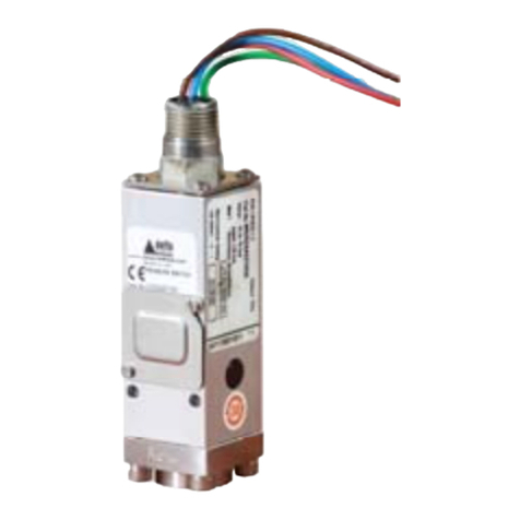
Pressure Switch models CS2 & CS4 are diaphragm
operated switches.
These diaphragms generate a force proportional to the
applied pressure and are balanced by a user adjustable
control spring. When the force exceeds that created by the
control spring, the diaphragm moves causing a push rod to
actuate a snap-acting microswitch.
Tools to be used for checking and
adjusting set point
The following calibration circuit is to be used to proceed
with the calibration of the set point or periodical functional
verification.
The test gauge should have a range similar to the
instrument under verification with an accuracy consistent
with the accuracy required to calibrate the set point.
Product Standards List
This product complies with the following standards:
IECEx ATEX UKEx
IEC 60079-0: Ed.7 EN 60079-0:2018 BS EN IEC 60079-
IEC 60079-1: Ed 7 EN 60079-1:2014 BS EN 60079-1:2014
IEC 60079-31: Ed.2 IEC 60079-31:2014 BS EN 60079-31:2014
IEC 60079-11: Ed 6 EN 60079-11:2012 BS EN 60079-11:2012
Marking
Flameproof models carry the following label markings:
Intrinsically safe models carry the following label
markings:
Input limitations for intrinsic safety:
Ui = 30V, Ii = 300mA, Ci = 1 nF; Li = 6.3 mH
Fig. 1 - Calibration Circuit
Special conditions of use
Warning: The instrument is not capable of
withstanding the 500V rms insulation test, this must
be taken into account when installing the
equipment
Warning: The equipment wire should be protected
from mechanical damage by the use of metal
conduit or an equivalent method, to prevent the
wiring from being subjected to tension or torque.
Warning: If the instrument is to be terminated
within a potentially explosive atmosphere, a
suitably certified junction box must be used.
Warning: The corrosive environmental conditions
may adversely affect the life and the type of
protection of the instrument. It is the responsibility
of the user to take suitable precautions that prevent
it, verify the compatibility of the environmental with
stainless steel and polymeric material.
Fig. 3 - Intrinsic Safety nameplate
Fig. 2 - Flameproof nameplate

Page 3 of 6 www.delta-mobrey.com
IOM-CS-F: AUG 2022
INSTALLATION
Mounting (All models)
The instruments are designed to be mounted vertically
with the process connection underneath. However,
mounting up to 45° from the vertical in any plane is
acceptable, although a small calibration shift may occur.
They can be mounted direct to the process. Select the
mounting point to avoid stresses, excessive shock,
vibration or temperature fluctuation being imparted to the
switch during the operation.
If sudden changes of pressure (pulsations) are likely then
we recommend that snubbers are fitted between the
process line and instrument.
Instruments should be mounted to avoid excessive heat
transfer from the process lines or adjacent plant.
With process fluid applications, that could crystallise/
solidify, we suggest the use of adequate chemical seals
and capillary.
Caution: Always hold a wrench on the pressure
entry hex when making a pressure connection to
the switch. Do not tighten by turning the electrical
entry; the microswitch assembly with factory sealed
leads has been carefully positioned at the factory.
Any disturbance may render this unit inoperative.
The following figures show the minimal installation tips
(Fig 4,5 and 6).
Caution: Check the connection thread size and
specification on the unit to avoid mismatching with
the process connection adaptor. See digit 11 of
product code.
Wiring
The instrument is equipped with wire with a cross section
of 0,75 mm2 (18 AWG). Individual cores of cable can be
coloured or numbered as show in fig.7.
The instrument may be equipped with micro switches
SPDT or DPDT.
Warning: Intrinsically safe instruments; where two
microswitches are fitted, the two switches must be
part of the same intrinsically safe circuit.
The entry parameters relevant for intrinsic safety
are listed on the nameplate of the instrument.
Electrical Connections
The instrument is provided with one electrical
entry. The thread type and size is marked on the
enclosure, just below the connection.
Warning: The leads are factory sealed. However,
the leads must be suitably protected against
mechanical damage and terminated in a suitable
junction box in accordance with local and national
codes.
Warning: Fittings/adaptor/plugs/terminal box used
for the electrical connection of the flameproof
instruments shall be certified according to IEC or
EN standards and shall guarantee the instrument a
level of protection to IP66
Warning: In order to guarantee the IP66 level of
protection and the non-loosening of fittings/
adaptor/plugs/terminal, we recommend sealing the
threads of connection with the same anaerobic
sealant. For instance, a sealant like Loctite ® 542
can be applied on the thread, before screwing
them.
Warning: The corrosive environmental conditions
may adversely affect the life and the type of
protection of the instrument. It is the responsibility
of the user to take suitable precautions that prevent
it, verify the compatibility of the environmental with
stainless steel and polymeric material.
Earthing connections
Warning: The instrument is to be grounded
according to applicable electrical codes. Make
use of the internal green wire and, if the cable is
not protected by metal tubing, make sure that the
equipment on which the instrument is installed is
suitably earthed.
2614
53
Fig. 7 - Wire Circuit
Fig. 4 - Remote installation
Fig. 5 - Direct Installation Fig. 6 - Installation on
Junction Box

Page 4 of 6 www.delta-mobrey.com
IOM-CS-F: AUG 2022
Operation Adjustments
Pressure switches are supplied and adjusted
at midscale falling, unless otherwise specified.
If the instrument has been ordered with
specific calibration values the adhesive label
shows the set point values.
It is a good rule to check the calibration values
marked on the relevant adhesive label, prior to
installation.
Calibration
Please follow the suggested steps below to
calibrate the set point of the instrument:
Connect the instrument to the pneumatic tools
in the normal installation position (see Fig.1).
If the instrument is supplied with a Junction
box, slacken the lid lock screw and unscrew
the lid. Connect the warning lamp according
the desired function.
Caution: Do not attempt to set the switch
outside the scale limits.
Though the unit may be set anywhere within
its range, for optimum performance, it is good
practice to have a set point value between
25% and 75% of span.
Connection C-NO terminal
- The circuit is open at the normal operating
pressure, the switch closes the circuit as the
pressure increases when the desired value is
reached
- The circuit is closed at the normal operating
pressure, the switch opens the circuit as the
pressure decreases when the desired value
is reached
Connection C-NC terminal
- The circuit is closed at the normal operating
pressure, the switch opens the circuit as the
pressure increases when the desired value is
reached
- The circuit is open at the normal operating
pressure, the switch closes the circuit as the
pressure decreases when the desired value
is reached
Pressurise the circuit and slowly increase the
pressure up to the set point.
Slide the cover upwards.
Using a screwdriver, rotate the range adjuster
right to left to increase the set point and left to
right to decrease the set point until the relative
lamp is turned ON, or OFF.
As a guide, one complete revolution of the
adjuster will alter the set point by
approximately 15% of the range.
Go to the normal operating pressure and
increase (or decrease) the pressure until the
relative lamp turn ON or OFF. Read the
pressure on the test gauge. Gradually adjust
the range adjuster and recheck again using
the lamp until the set point is achieved with the
required accuracy.
Slide the cover downwards.
Write the set point on the adhesive label
Periodical calibration checks
Connect the instrument to the pneumatic tools
in the normal installation position (see Fig.1).
Connect the warning lamp according to the
desired function.
Set point calibrated with increasing
pressure
From atmospheric pressure, pressurise the
circuit and increase the pressure up slowly to
the set point (the warning lamp is shown as
ON).
Record the pressure read on the test gauge.
Return to atmospheric pressure.
Repeat the above operation twice.
Set point calibrated with decreasing
pressure
From atmospheric pressure, pressurise the
circuit up to upper range value.
Decrease the pressure down slowly to the
set point (the warning lamp switches ON).
Record the pressure read it on the test
gauge.
Return to the upper range pressure value.
Repeat the above operation twice.
Evaluation of set point value and
repeatability
With all the above values detected, calculate:
- Average set point value
- Repeatability correspondent to the max
difference of the detected set point values.
If the average set point is different from the
expected, the instrument must be recalibrated.
If the repeatability is higher than the value in
the product Technical Data Sheet replace the
instrument with a new one and contact the
factory.
End of verification
Fig. 7 - Set point adjusting

Page 5 of 6 www.delta-mobrey.com
IOM-CS-F: AUG 2022
Replacement parts
IMPORTANT NOTE: Operations involving
the replacement of essential components
must be carried out at our workshop,
especially for instruments with a flameproof
certificate; this is to guarantee the complete
and correct restoration of the products
original characteristics.
Warning: The equipment contains no user-
replaceable parts and is not intended to be
repaired by the user.
Warranty
See Standard Conditions of Sale.
Periodical visual inspection
Isolate the unit from process and power.
Warning: The flameproof instruments
installed in explosive atmospheres of the
combustible dust, must be periodically
cleaned externally in order to remove any
accumulation of dust.
Verify the integrity of the electrical unit using
IEC 60079-17 as a guide.
Verify there is no external leakage of the
process media.
Should the diaphragm fail, the process will
vent to the atmosphere via a control orifice
without pressurising the switch enclosure.
Periodically ensure the vent area does not
become blocked and vent plug has not
degraded. Ensure that the vent area is not
obstructed.
Safety Integrity Level (SIL)
instrument and installation
requirements
Refer to Functional Safety Manual CS Series.
Commissioning
The instrument starts operating as soon as it
is energised and the root valve is opened.
Inspections and maintenance
The instrument is maintenance-free but it is
good practice to have periodical inspections
(visual and functional).
Inspections should be carried out at least once
a year depending upon operating,
environmental conditions and customer plan.
Caution: It is recommended that instruments
used to provide an alarm or a shutdown safety
related are operated periodically to ensure
they are functioning correctly.
If further maintenance is required seek advice
from Delta Mobrey before attempting repair or
replacement of parts.
Periodical functional verification
The verification consists of a check of the set
point. This verification is done, usually by
removing the instrument from the plant and
performing the verification in a test room (see
periodical /calibration check paragraph).
Warning: Flameproof instruments. Before
removing the lid or the cable gland check that
the electrical supply is not energised and that
no explosive atmosphere is present.
If the verification is done on site, the preferred
procedure is the verification of the entire loop
without removing the lid or the cable gland.
Warning: The flameproof instruments maybe
checked on site only if the apparatus suitable
for explosive atmospheres is used.
Warning: Verify that the loop is in a safe
configuration before acting on the valves and
instrument. Do not dispose of the process fluid
into the environment if this causes pollution or
personal injury.
Decommissioning
Warning: Verify that the loop is in a safe
state before working on the valves and
instrument. Power off the instrument and
verify, especially for a flameproof product, the
absence of an explosive atmosphere. Do not
dispose of the process fluid into the
environment if this causes pollution or
personal injury.
- Isolate the instrument from the process and
depressurise utilising the valves
- Disconnect all the live terminals and insulate
the cables
- Disconnect the grounding
- Remove the cable gland
- Disconnect the instrument from the process
connection.
Warning: The process fluid can be hot and or
corrosive.
Disposal
The instrument is mainly made of aluminium
and stainless steel. Remove the microswitch
and clean the wetted parts before scrapping
the instrument.

Page 6 of 6 www.delta-mobrey.com
IOM-CS-F: AUG 2022
Model code
Enclosure
Model
Electrical Entry
Material of Wetted Part
Range
Switch
Process Connection
Options & Treatments
Special Engineering
DIMENSIONS
Enclosures Styles
www.delta-mobrey.com
This manual suits for next models
2
Other delta-mobrey Switch manuals
Popular Switch manuals by other brands

Cisco
Cisco Catalyst 2960-S Series Started guide
Hubbell
Hubbell Circuit-Lock installation instructions
Uniclass
Uniclass AHEP04A Quick installation guide

3Com
3Com Switch 7700 Configuration guide

United Electric Controls
United Electric Controls ONE Series Installation and maintenance instructions
SMC Networks
SMC Networks ZSE40A Operation manual
