manuals.online logo
Brands
  1. Home
  2. •
  3. Brands
  4. •
  5. Kramer
  6. •
  7. Switch
  8. •
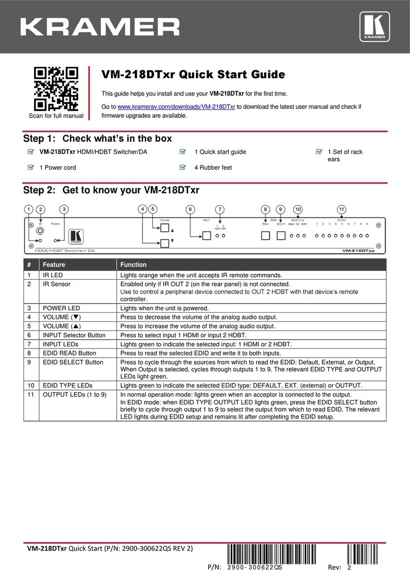
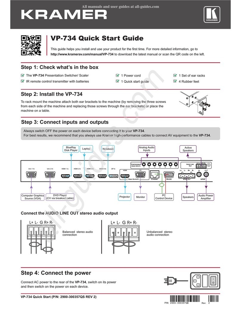
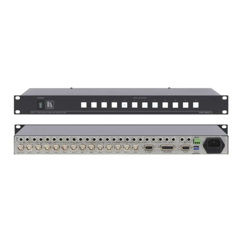
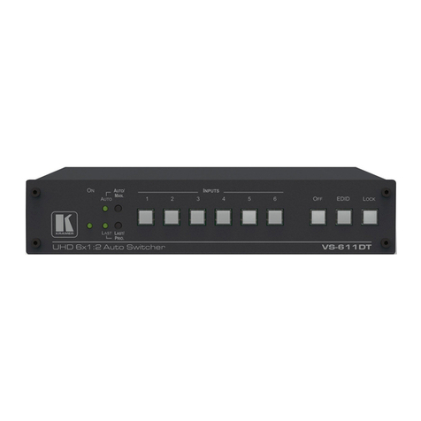
  9. Kramer VP-732 User manual

Kramer VP-732 User manual

VP-732 Quick Start (P/N: 2900-300893QS REV 2)
P/N:
2900- 300893QS
Rev:
2
Scan for full manual
VP-732 Quick Start Guide
This guide helps you install and use your VP-732 for the first time.
Go to www.kramerav.com/downloads/VP-732 to download the latest user manual and check if firmware
upgrades are available.
Step 1: Check what’s in the box
VP-732 Presentation Switcher/Dual Scaler
4 Rubber feet
1 Set of rack ears
1 Power cord
1 Quick start guide
IRremote control transmitter with batteries
Step 2: Get to know your VP-732
#
Feature
Function
1
IR
Receiver
Receives signals from the remote control transmitter.
2
LED
Lights red when the unit receives IR remote commands.
3
PROGRAM
INPUTS Buttons
(light green
when selected)
UNIV 1 –4
Press to select one of the universal inputs (configured via the OSD menu) and the appropriate
audio source.
4
HDMI 1 –4
Press to select one of the HDMI inputs.
5
DP 1 –2
Press to select one of the DP inputs.
6
PROGRAM BLANK Button
Press to toggle between a blank screen (blue or black) and the video display. Can be configured
to mute the audio signal at the same time.
Configureusing the OSD menu.
7
PROGRAM FREEZE Button
Press to freeze/unfreeze the video display. Can be configured to mute the audio signal at the
same time. Configure using the OSD menu.
8
PIP / PREVIEW
INPUTS Buttons
(light yellow
when selected)
UNIV 1 –4
Press to select one of the universal inputs (configured via the OSD menu) and the appropriate
audio source.
9
HDMI 1 –4
Press to select one of the HDMI inputs.
10
DP 1 –2
Press to select one of the DP inputs.
11
PIP / PREVIEW BLANK Button
Press to toggle between a blank screen (blue or black) and the video display. Can be configured
to mute the audio signal at the same time.
Configureusing the OSD menu.
12
PIP / PREVIEW FREEZE
Button
Press to freeze/unfreeze the video display. Can be configured to mute the audio signal at the
same time. Configure using the OSD menu.
13
PREVIEW MODE Button
Pressto toggle between PIP and Preview Mode operation.
14
MENU Button
Press to display the OSD menu screen. Press again to return to normal operation.
#
Feature
Function
15
OSD Navigation
Buttons
(when not in
OSD menu,
and control
volume level)
ENTER
Press to move to the next level or to accept a new parameter.
Press to decrease the range by one step or move to the previous level.
When not in the OSD menu, press to decrease the volume level.
Press to move up one step (in the same level), or move to the previous slide when running a
slideshow.
Press to increase the range by one step.
When not in the OSD menu, press to Increase the volume level.
Press to move down one step (in the same level), or move to the next slide when running a
slideshow.
16
RESET TO XGA/720p Button
Press and hold to reset to the default resolution (toggles between RESET TO XGA and 720p).
17
PANEL LOCK Button
Press and hold to lock/unlock the front panel to prevent unintentional operation.
18
USB Connector
Connects to a USB drive to download a Logo and save settings.
#
Feature
Function
19
VIDEO INPUTS
HDMI IN 1 –4
Connectors
Connect to the HDMI sources.
20
UNIV IN 1 –4 15-pin HD
Connectors
Connect to universal video sources that can be configured as computer graphics, composite
video, s-Video (Y/C) or component video.
21
DP IN 1 -2 DisplayPort
Connectors
Connect to DP sources.
22
VIDEO OUTPUTS
PROG/PREVIEW
HDMI 1 Connector
Connect to a PROGRAM/PREVIEW HDMI acceptor (selectable).
23
PROGRAM HDMI 2
Connector
Connect to a PROGRAM HDMI acceptor.
24
PROGRAM DP
Connector
Connect to a PROGRAM DP acceptor.
25
PC (PREVIEW)
15-pin HD Connector
Connect to a PREVIEW computer graphics acceptor.
26
AUDIO INPUTS 1 –10
3.5 Mini Jacks
Connect to unbalanced stereo analog audio sources.
27
AUDIO LINE OUT
5-pin Terminal Block
Connect a balanced stereo analog audio acceptor (see Step 4).
28
RS-232 9-pin D-sub Connector
Connect to a PC or serial controller.
29
ETHERNET RJ-45 Connector
Connect to a LAN.
30
SPKR OUT
4-pin Terminal Block
Connect to speakers.
31
S/PDIF
INPUT
3.5 Mini Jack
Connect to a digital audio source.
32
OUTPUT
3.5 Mini Jack
Connect to a digital audio acceptor.
33
Power Connector
Connect to the power cord and the mains electricity.
34
Power Fuse
Fuse for protecting the device.
35
Power switch
Switch for turning the unit ONor OFF.
Step 3: Install VP-732
Install VP-732 using one of the following methods:
•Remove the three screws from each side of the unit, reinsert those screws through
the rack ears and mount on a 19" rack.
•Attach the rubber feet and place the unit on a flat surface.
Step 4: Connect the inputs and outputs
Always switch OFF the power on each device before connecting it to your VP-732. For best results, we recommend that you always
use Kramer high-performance cables to connect AV equipment to VP-732.
Connecting Balanced / Unbalance Stereo Audio Outputs:
Balanced
Unbalanced
Universal Connectors Pinout:
PIN #
VGA
COMP
s-Video
CV
1
R
Pr
2
G
Y
S_Y
Composite video
3
B
Pb
S_C
9
+5VD
12
EDID_SDA
13
H_Sync
14
V_Sync
15
EDID_SCL
Note: PINs 5, 6, 7, 8 and 10 are GND.
Step 5: Connect the power
Connect the power cord to VP-732 and plug it into the mains electricity.
Safety Instructions
Caution:
There are no operator serviceable parts inside the unit.
Warning:
Use only the power cord that is supplied with the unit.
Warning:
Do not open the unit. High voltages can cause electrical shock! Servicing by qualified personnel only.
Warning:
Disconnect the power and unplug the unit from the wall before installing.
See www.KramerAV.com for updated safety information.
Step 6: Set operation parameters via the OSD menu
Enter the OSD menu via the MENU button on the front panel or the
IR remote control transmitter. Select a menu item and set parameters
as required. Sub-menus include: Input, Picture, Output, PIP, Audio,
Setup and Info.
Note: if you do not see an image, verify that the display, TV, or
projector is in good working order, is connected to the VP-732, and
that the VP-732 is selected as its source. If you still don't see an
image, press and hold the RESET TO XGA/720P button for 5
seconds to reset the output to XGA or 720p resolution.
Step 7: Operate VP-732 via the front panel buttons and via the:
IR Remote Control Transmitter
RS-232 / Protocol 3000 & Legacy protocol and Ethernet / web pages
RS-232 Default Parameters
Baud Rate:
115,200
Data Bits:
8
Stop Bits:
1
Parity:
None
Command Format:
ASCII
Protocol 3000 example (set the remote input switching of video to HDMI 1 from HDMI In 2):
#ROUTE 1,1,2<CR>
Legacy Protocol example (switch PIP input to UNIV3): Y 0 92 2<CR>
Ethernet / Default Parameters
IP Address:
192.168.1.39
Subnet Mask:
255.255.255.0
Default Gateway:
192.168.1.254
Default TCP Port #:
80
Maximum TCP Ports:
1
Embedded Web Pages:
•Routing & Scaling –select Program and Preview inputs, adjust size and
position of the video image, and adjust the audio volume
•Device settings –set the device name, change Ethernet parameters, perform
factory reset and view system information
•Input Settings –configure the Program and PIP/Preview input settings
•Output settings –configure the Program and PIP/Preview output settings
•Audio Settings –configure the audio output settings
•Miscellaneous Video Settings –configure video settings such as Frame Lock,
Auto Image, Switching Mode, Frame Latency
•EDID management –read the EDID from any of the outputs, from a list of
default resolutions or from a file on your PC
•Advanced Settings –configure settings such as default input resolution, logo
display, video overlay, Blank and Freeze mode, screen color when there is no
signal, power settings
•Custom Resolutions –save up to four custom resolution settings each for the
input and the output
•Security –activate/deactivate the security mode and change the password
Performing a Factory Reset:
Note: Factory reset includes resetting the IP address.
•From the OSD: Go to Menu > Setup > Factory Reset and press Enter to Confirm.
•Using the front panel reset button: Press and hold the Reset to XGA/720p button while powering up the machine.
Other manuals for VP-732

2

Other Kramer Switch manuals

Kramer VP-440X User manual

Kramer

Kramer VP-440X User manual

Kramer VS-81HDxl User manual

Kramer

Kramer VS-81HDxl User manual

Kramer VS-211UHD User manual

Kramer

Kramer VS-211UHD User manual

Kramer VP-1201 User manual

Kramer

Kramer VP-1201 User manual

Kramer VS-41HDCP User manual

Kramer

Kramer VS-41HDCP User manual

Kramer VP-443 User manual

Kramer

Kramer VP-443 User manual

Kramer PT201VGA User manual

Kramer

Kramer PT201VGA User manual

Kramer VP-81SID User manual

Kramer

Kramer VP-81SID User manual

Kramer SWT3-41-U-T User manual

Kramer

Kramer SWT3-41-U-T User manual

Kramer VP-429H2 User manual

Kramer

Kramer VP-429H2 User manual

Kramer FC-46xl User manual

Kramer

Kramer FC-46xl User manual

Kramer VS-622DT User manual

Kramer

Kramer VS-622DT User manual

Kramer KIT-401 User manual

Kramer

Kramer KIT-401 User manual

Kramer VM-218DTxr User manual

Kramer

Kramer VM-218DTxr User manual

Kramer VIA Collage User manual

Kramer

Kramer VIA Collage User manual

Kramer VP-214DS User manual

Kramer

Kramer VP-214DS User manual

Kramer VS-81SP User manual

Kramer

Kramer VS-81SP User manual

Kramer DIP-22 User manual

Kramer

Kramer DIP-22 User manual

Kramer FC-321 User manual

Kramer

Kramer FC-321 User manual

Kramer VS-41HC User manual

Kramer

Kramer VS-41HC User manual

Kramer RC-11TB User manual

Kramer

Kramer RC-11TB User manual

Kramer VP-61N User manual

Kramer

Kramer VP-61N User manual

Kramer VP-28 User manual

Kramer

Kramer VP-28 User manual

Kramer VP-733 User manual

Kramer

Kramer VP-733 User manual

Popular Switch manuals by other brands

IOGear GCL1908 quick start guide

IOGear

IOGear GCL1908 quick start guide

Aluratek AKSP04 quick start guide

Aluratek

Aluratek AKSP04 quick start guide

PTN WUH4ARC-8K user manual

PTN

PTN WUH4ARC-8K user manual

H3C H3C S5100-SI Operation manual

H3C

H3C H3C S5100-SI Operation manual

TRENDnet TEG-S50G Quick installation guide

TRENDnet

TRENDnet TEG-S50G Quick installation guide

Cabletron Systems 9E106-06 user guide

Cabletron Systems

Cabletron Systems 9E106-06 user guide

Siemens RUGGEDCOM RS910W installation manual

Siemens

Siemens RUGGEDCOM RS910W installation manual

H3C S7500 Series manual

H3C

H3C S7500 Series manual

Allied Telesis AT-FS716 installation guide

Allied Telesis

Allied Telesis AT-FS716 installation guide

SMC Networks TigerStack II SMC8926EM Specifications

SMC Networks

SMC Networks TigerStack II SMC8926EM Specifications

Giovenzana FGR2 instruction manual

Giovenzana

Giovenzana FGR2 instruction manual

NETGEAR ProSAFE GS105PE installation guide

NETGEAR

NETGEAR ProSAFE GS105PE installation guide

Cisco IE 3000 Hardware installation guide

Cisco

Cisco IE 3000 Hardware installation guide

ADTRAN NetVanta 1224 PoE Specification sheet

ADTRAN

ADTRAN NetVanta 1224 PoE Specification sheet

Rosewill RC-409LX user manual

Rosewill

Rosewill RC-409LX user manual

Extron electronics System 8 Plus user manual

Extron electronics

Extron electronics System 8 Plus user manual

D-Link DGS-3630-28TC Quick installation guide

D-Link

D-Link DGS-3630-28TC Quick installation guide

Pacific Antenna Easy TR Switch quick start guide

Pacific Antenna

Pacific Antenna Easy TR Switch quick start guide

manuals.online logo
manuals.online logoBrands
  • About & Mission
  • Contact us
  • Privacy Policy
  • Terms and Conditions

Copyright 2025 Manuals.Online. All Rights Reserved.