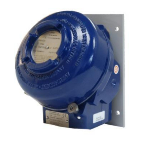
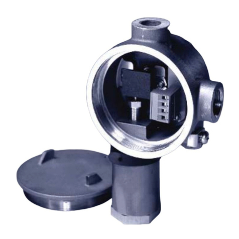
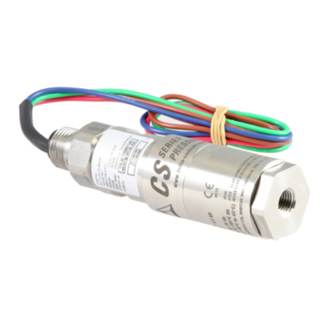
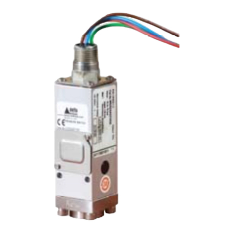
delta-mobrey VM Series Guide

www.delta-mobrey.com
IOM-VM-B: NOV 2020
Installation, Operation &
Maintenance Instructions
VM Series
Models VM2, VM4 (Pressure Switches)
General
The unit is manufactured, checked and supplied in
accordance with our published specification, and
when installed and used in normal or prescribed
applications, with the lid in place and within the
parameters set for mechanical and electrical
performance, will not cause danger or hazard to life
or limb.
THE USERS ATTENTION IS DRAWN TO
THE FACT THAT, WHEN THE UNIT IS
‘LIVE’ WITH RESPECT TO ELECTRICAL
OR PRESSURE SUPPLIES, A HAZARD
MAY EXIST IF THE UNIT IS OPENED OR
DISMANTLED.
UNITS MUST BE SELECTED AND
INSTALLED BY SUITABLY TRAINED AND
QUALIFIED PERSONNEL IN
ACCORDANCE WITH APPROPRIATE
CODES OF PRACTICE SO THAT THE
POSSIBILITY OF FAILURE RESULTING IN
INJURY OR DAMAGE CAUSED BY
MISUSE OR MISAPPLICATION IS
AVOIDED.
Operating principles
Pressure Switch models VM2 (low pressure) and
VM4 (high pressure) are diaphragm operated
switches.
These diaphragms generate a force proportional to
the applied pressure and are balanced by a user
adjustable control spring. When the force exceeds
that created by the control spring, the diaphragm
moves causing a push rod to actuate a snap-acting
micros-witch.
CERTIFICATIONS
Flameproof Models
Flameproof models carry the following markings:
Ex db IIC T6 Gb * ≤ Ta ≤ 65°C
II 2 GD Ex db IIC T5 Gb * ≤ Ta ≤ 80°C 0598
Ex tb IIIC T75 Db * ≤ Ta ≤ 65°C
Ex tb IIIC T90 Db * ≤ Ta ≤ 80°C
* the minimum ambient temperature (Ta) is dependent on
the O-ring material of the enclosure seals, as below;
Nitrile -35°C
Fluoroelastomer -20°C
Fluorosilicone -55°C
Special Conditions of Use
The certificate number has an 'X' suffix which
indicates that special conditions of installation and
use apply. Those installing or inspecting this
equipment must have access to the contents of the
certificate or these instructions. The conditions listed
in the certificate are reproduced below:
USE HIGH TEMPERATURE CABLE
SUITABLE FOR AT LEAST 100°C.
THE CABLE GLAND, STOPPING PLUG
OR BLANKING ELEMENT USED SHALL
BE Ex d/tb IIC/IIIC Gb/Db RATED FOR A
SERVICE TEMPERATURE OF -55°C TO
+100°C MINIMUM.
ONLY ONE SUITABLY RATED AND
APPROVED THREAD ADAPTOR SHALL
BE USED WHEN ONE IS REQUIRED.
FLAMEPATHS ARE NOT INTENDED TO
BE REPAIRED.
INSTALLATION
Mounting (All models)
The instruments are designed to be mounted
vertically with the process connection underneath.
However, mounting up to 45° from the vertical in any
plane is acceptable, although a small calibration shift
may occur. They can be mounted either direct to
process, or to a wall or panel, using the mounting
holes provided. Select the mounting point so as to
avoid excessive shock, vibration or temperature
fluctuation. Instruments should be mounted to avoid
excessive heat transfer from the process lines or
adjacent plant.
To avoid undue stresses being imparted to the
instrument when wall/panel mounted, it is
recommended that a short length of flexible line be
installed between the instrument and process line. If
sudden changes of pressure (pulsations) are likely
then we recommend that snubbers are fitted
between the process line and instrument.
ATEX
ATEX
ATEX
ATEX

www.delta-mobrey.com
IOM-VM-B: NOV 2020
ALWAYS HOLD A WRENCH ON THE
PRESSURE ENTRY HEX WHEN MAKING
PRESSURE CONNECTION TO THE
SWITCH. DO NO TIGHTEN BY TURNING
THE ENCLOSURE.
CHECK THE CONNECTION THREAD
SIZE AND SPECIFICATION ON THE UNIT
TO AVOID MIS-MATCHING WITH THE
PROCESS CONNECTION ADAPTOR. SEE
DIGIT 11 OF PRODUCT CODE.
Installation of electrical adaptors and
cable glands to the electrical entry
One electrical entry is provided. The standard entry
is either a single ISO M20 x 1.5 or ½” NPT thread.
The actual thread type is stamped on the enclosure
next to the entry.
TAKE CARE TO SELECT AND INSTALL
AN ATEX CERTIFIED ADAPTOR THAT
DOES NOT REDUCE THE ENCLOSURE’S
DEGREE OF PROTECTION.
UNUSED ENTRIES MUST BE FITTED
WITH ATEX CERTIFIED FLAMEPROOF
STOPPING PLUGS.
IT IS A SAFETY REQUIREMENT THAT AT
LEAST 5 FULL THREADS ARE ENGAGED
BETWEEN THE ADAPTER, CABLE
GLAND OR STOPPING PLUG, AND THE
ELECTRICAL ENTRY WHEN THE UNIT IS
IN OPERATION. NEVER OPERATE THE
UNIT UNLESS THIS CONDITION IS MET.
Wiring
DISCONNECT ALL SUPPLY CIRCUITS
BEFORE WIRING.
WIRE IN ACCORDANCE WITH LOCAL
AND NATIONAL CODES. USE CABLES
NO LARGER THAN 2.5 MM 2 (14 AWG).
DO NOT EXCEED ELECTRICAL RATINGS
STATED IN LITERATURE AND ON
NAMEPLATES.
REPLACE COVER/LID, TIGHTEN
GLANDS, ADAPTORS, AND STOPPING
PLUG, BEFORE ENERGISING ANY
CIRCUITS.
The three switch terminals are clearly marked
“NORMALLY CLOSED”, “NORMALLY OPEN” and
“COMMON”. The following diagram (Fig. 1) can be
used as a guide for wiring.
Insert bare wires fully into the terminal block and
tighten securely. Keep wiring tails to a minimum and
check that wires do not interfere with the operating
mechanism. Use the earthing / grounding points
provided. The terminal strip is designed to be pulled
out to assist wiring up.
End of line resistors
Some products may be supplied to order fitted with
end of line resistors. Resistors in use may generate
a heat source. The type, quantity, configuration,
fitment method and allowable electrical loads are
limited by the scope of the certification.
NEVER FIT END OF LINE RESISTORS OR
MODIFY WITHOUT REFERENCE TO
DELTA MOBREY
Replacing cover / lid on Flameproof
enclosures
Before connecting to electrical power, screw on
cover/lid hand tight making sure that mating
surfaces of the lid and enclosure are in contact. Use
the locking screw provided to prevent casual and
unauthorised removal of the cover/lid.
DO NOT USE GREASES OR
LUBRICANTS WHICH ARE NOT
COMPATIBLE WITH THE ENVIRONMENT
AND / OR PROCESS.
IT IS A SAFETY REQUIREMENT THAT AT
LEAST 5 FULL THREADS ARE ENGAGED
BETWEEN THE COVER / LID AND THE
ENCLOSURE WHEN THE UNIT IS IN
OPERATION. NEVER OPERATE THE
UNIT UNLESS THIS CONDITION IS MET.
OPERATION
Adjustments
Switches are supplied calibrated at the midpoint of
their range and to a falling pressure or temperature
unless otherwise specified.
Set point adjustments (All Models):
1. Isolate the instrument from process and power.
2. Remove the lid to allow access
3. Slacken the set point lock screw.
4. Using a suitable spanner, rotate the range
adjuster clockwise to increase the set point and
counter-clockwise to decrease the set point.
5. Tighten the set point lock screw.
ATEX
Terminal
Single Double
ATEX
ATEX
ATEX
ATEX
ATEX
ATEX
ATEX
ATEX
Fig.1

www.delta-mobrey.com
IOM-VM-B: NOV 2020
Note: For accurate setting, a suitable pressure
gauge must be used in conjunction with the above
procedure. Do not attempt to set the switch outside
the scale limits.
Though the unit may be set anywhere within its
range, for optimum performance, it is good practice
to have a set point value between 25% and 75% of
span.
MAINTENANCE
DE-ENERGIZE ALL CIRCUITS AND WAIT
5 MINUTES BEFORE LOOSENING OR
REMOVING THE COVER/LID, GLANDS,
ADAPTORS, OR STOPPING PLUG.
Inspections should be carried out at quarterly to
yearly intervals depending upon operating
conditions. Isolate the unit from process and power
and remove the lid. Check all terminals for
tightness. Check that cable tails are not fouled or
chafed. Check for internal condensation. Check
that the gasket is seated properly in the lid recess
and is not worn. Keep the enclosure and lid clear of
dust build up.
It is recommended that instruments used to provide
an alarm are operated periodically to ensure they
are functioning correctly.
If further maintenance is required seek advice from
DELTA MOBREY before attempting repair or
replacement of parts.
Should the diaphragm fail the process will vent to
atmosphere via a control orifice without pressurising
the switch enclosure. Periodically ensure the vent
area does not become blocked and vent plug has
not degraded. Ensure that the vent area is not
obstructed.
Replacement Parts
Use only factory authorised parts and the fitting
instructions that are supplied.
Warranty
See Standard Conditions of Sale.
DIMENSIONS
Models VM2, VM4 (Pressure Switches)
ATEX
This manual suits for next models
2
Other delta-mobrey Switch manuals
Popular Switch manuals by other brands

Black Box
Black Box LGB2008A-R2 brochure

HYDACELECTRONIC
HYDACELECTRONIC ETS 3000 operating instructions

TV One
TV One MX-3141CSVA instruction manual

Celabs
Celabs HM41SR instruction manual

Smart Technologies
Smart Technologies X-Port 20 Switch XP20-2000i installation guide

Little Giant
Little Giant ACS-3 Installation, operation, maintenance & repair parts
