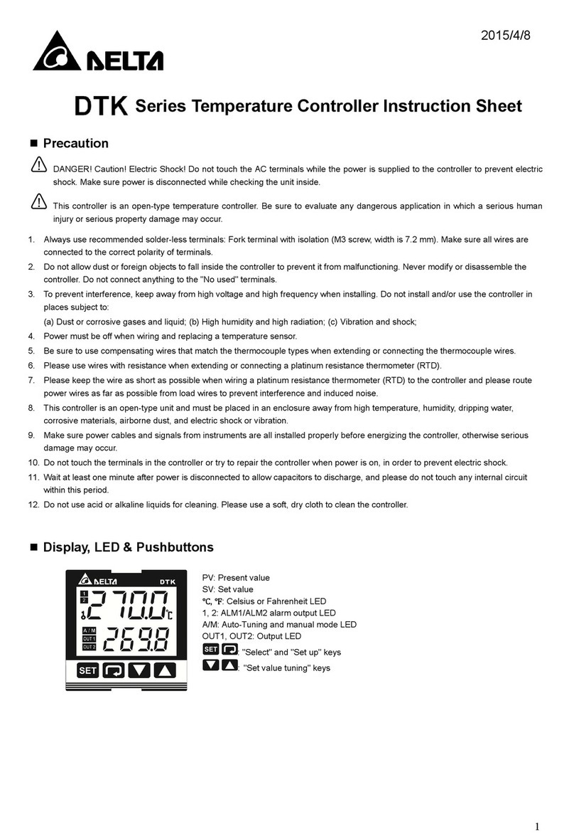
Series Temperature Controller
Precaution
DANGER! Caution! Electric Shock!
1. Do not touch the AC terminals while the power is supplied to the controller to prevent an electric shock.
2. Make sure power is disconnected while checking the unit inside.
WARNING!
This controller is an open-type temperature controller. Make sure to evaluate any dangerous application in which a
serious human injury or serious property damage may occur.
1. Do not allow dust or foreign objects to fall inside the controller to prevent it from malfunctioning.
2. Never modify or disassemble the controller.
3. Do not connect anything to the “No used” terminals.
4. Must turn power off when wiring and changing a temperature sensor.
5. This controller is an open-type unit and must be placed in an enclosure away from high temperature, humidity, dripping
water, corrosive materials, airborne dust and electric shock or vibration.
6. Wait at least one minute after power is disconnected to allow capacitors to discharge, and please do not touch any
internal circuit within this period.
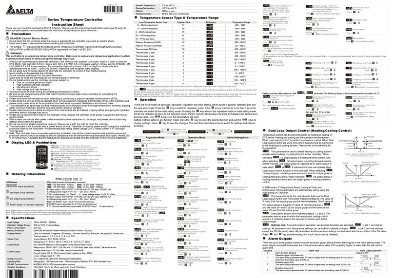
Ordering Information
Series DTA: Delta A Series Temperature Controller
Panel Size 4848, 4896, 9648, 7272, 9696
Output Selection
R: Relay output, SPDT (SPST: 1/16 DIN size), 250VAC, 5A
V: Voltage Pulse output, 14V+10% ~ -20% (Max. 40mA)
C: Current output, 4~20mA
Communication (Optional) 0: No interface
1: RS-485
Current Transformer
(Optional)
None: No CT function (Current transformer is not provided)
T: Current transformer is provided (only DTA7272 series support)
Display, LED & Pushbuttons
: Mode key. Press this key to set parameters within each function mode.
: Up key. Press this key to increase values displayed on the SV display. Hold down this key to speed up the
incremental action.
:Down key. Press this key to decrease values displayed on the SV display. Hold down this key to speed up the
decrements
Specifications
Input voltage 100 ~ 240VAC, 50/60Hz
Display method 7-segment digit LED Display
Process value (PV): Red, Set point (SV): Green
Sensor type
Thermocouple: K, J, T, E, N, R, S, B, U, L, Txk
3-wire Platinum RTD: Pt100, JPt100
Copper resistor: Cu50
Control mode PID, ON/OFF control or Manual tuning
Display accuracy 0.1% of measuring range
Sampling rate 500 msec/per scan
Ambient temperature 0oC ~ 50oC
Relative humidity 35% ~ 80% (non-condensing)
Operation
1. Operation Mode: Perform per the settings of related control parameters
LED Display Explanation Default
RUN/STOP: Control setting begins. Run ( ) or Stop ( ) mode on the
SV display. RUN
ALARM1 HIGH: Upper-limit alarm 1 4.0 oC
ALARM1 LOW: Lower-limit alarm 1 4.0 oC
ALARM2 HIGH: Upper-limit alarm 2 4.0 oC
ALARM2 LOW: Lower-limit alarm 2 4.0 oC
Setting lock: Lock 1 ( ), Lock 2 ( ) or OFF ( ) on the SV
display. Lock 1 mode can lock all settings and Lock 2 mode only can lock others
than SV value. When OFF mode is selected, the Lock function will be OFF. If you
press and key simultaneously, the “Lock” status can be released and the
controller will be back to the previous display.
OFF
OUT: Output value display and output value adjustment in manual tuning control 0
CT: In case of using an external current transformer (CT), the controller displays the
current value being measured by CT, if the control output is ON Read only
2. Regulation Mode: Set the control parameters
LED Display Explanation Default
AT: Auto-tuning setting. When AT key is set to ON ( ). OFF
P: Proportional Band (PID control) 47.6
I: Integral Time (PID control) 260
D: Derivative Time (PID control) 41
PdoF: Offset output when P or PD control function is ON. 0
ioF: Default value of integral volume when PID control function is ON and integral
time constant is not equal to 0(zero). 0
HTS: Set Heating hysteresis when ON/OFF control function is ON. 0
CTS: Set Cooling hysteresis when ON/OFF control function is ON. 0
HTPD: PID heating control cycle setting (PID control) C, V: 4sec
R : 20sec
CLPD: PID cooling control cycle setting (PID control)
TPOF: Regulate temperature deviation value 0
LED Display Explanation Default
TPGN: Regulate temperature gain value 0
CRHI: Regulate 20mA output deviation value 0
CRLO: Regulate 4mA output deviation value 0
3. Initial Setting Mode: Initial settings of the controller and communication parameters
LED Display Explanation Default
INPUT: Select input temperature sensor type PT2
UNIT: Temperature display unit, oC ( ) and oF ( ) oC
T-HIGH: Upper limit for temperature range 500.0
T-LOW: Lower limit for temperature range -20.0
CONTROL: Control method setting on the SV display: PID ( ), ON/OFF
control ( ), or manual tuning ( )
PID
SWITCH: Select Heating ( ) or Cooling ( ) action HEAT
AL1 SET: Alarm 1 setting 0
AL2 SET: Alarm 2 setting 0
C SELECT : ASCII, RTU communication formats selection ASCII
C WE: Write-in function disable/enable OFF
C NO: Address setting 1
BPS: Baud rate setting 9,600
LENGTH: Data length setting 7
PARITY: Parity bit setting E
STOP BIT: Stop bit setting 1
Temperature Sensor Type & Temperature Range
Sensor type Display Range Sensor type Display Range
Pt100 0.0 ~ 100.0°C E 0 ~ 600°C
Pt100 -20.0 ~ 500.0°CT -20.0 ~ 400.0°C
Pt100 -200 ~ 600°C T -200 ~ 400°C
JPt100 0.0 ~ 100.0°C J -20.0 ~ 400.0°C
JPt100 -20.0 ~ 400.0°CJ -100 ~ 850°C
Cu50 -50.0 ~ 150.0°CK -20.0 ~ 500.0°C
Cu50 -50 ~ 150°C K -200 ~ 1300°C
B 100 ~ 1800°C L -200 ~ 850°C
S 0 ~ 1,700°C U -200 ~ 500°C
R 0 ~ 1,700°C Txk -200 ~ 800°C
N -200 ~ 1,300°C
Alarm Outputs
Set Value Alarm Type
0 Alarm function disabled
1
Deviation upper- and lower-limit:
This alarm output operates when PV value is higher than the setting value SV+(AL-H) or lower than the
setting value SV-(AL-L).
2 Deviation upper-limit:
This alarm output operates when PV value is higher than the setting value SV+(AL-H).
3 Deviation lower-limit:
This alarm output operates when PV value is lower than the setting value SV-(AL-L).
4
Reverse deviation upper- and lower-limit:
This alarm output operates when PV value is in the range of the setting value SV+(AL-H) and
SV-(AL-L).
5
Absolute value upper- and lower-limit:
This alarm output operates when PV value is higher than the setting value AL-H or lower than setting
value AL-L.
6 Absolute value upper-limit:
This alarm output operates when PV value is higher than the setting value AL-H.
7 Absolute value lower-limit:
This alarm output operates when PV value is lower than the setting value AL-L.
8
Deviation upper- and lower-limit with standby sequence:
This alarm output operates when PV value reaches set value (SV value) and the value is higher than
the setting value SV+(AL-H) or lower than the setting value SV-(AL-L).
9
Deviation upper-limit with standby sequence:
This alarm output operates when PV value reaches set value (SV value) and the reached value is
higher than the setting value SV+(AL-H).
10
Deviation lower-limit with standby sequence:
This alarm output operates when PV value reaches the set value (SV value) and the reached value is
lower than the setting value SV-(AL-L).
11 Hysteresis upper limit alarm output: this alarm output operates if PV value is higher than the setting
value SV+(AL-H). This alarm output is OFF when PV value is lower than the setting value SV+(AL-L).
12 Hysteresis lower limit alarm output: this alarm output operates if PV value is lower than the setting value
SV-(AL-H). This alarm output is OFF when PV value is higher than the setting value SV-(AL-L).
13
CT alarm output:
This alarm operates when the current measured by transformer (CT) is lower than AL-L or higher than
AL-H (This alarm output is available only for the controller with current transformer). You can set current
alarm range between 0.5A~ 30A, display resolution is 0.1A and measure accuracy is +/- 0.5A.
Communication Parameters List
Communication protocol: Modbus (ASCII) , 2400 ~ 38400bps
Function code: 03H to read the contents of register (Max. 3 words); 06H to write 1 (one) word into register.
Address Content Explanation
4700H (R) Process value (PV) Measuring unit is 0.1oC or oF
4701H Set point (SV) Unit is 0.1, oC or oF
4702H Upper-limit alarm 1
4703H Lower-limit alarm 1
4704H Upper-limit alarm 2
4705H Lower-limit alarm 2
4706H Upper-limit of temperature range The data content should not be higher than the temperature range.
4707H Lower-limit of temperature range The data content should not be lower than the temperature range.
4708H PB Proportional band 0.1 ~ 999.9, unit is 0.1
4709H Ti Integral time 0 ~ 9,999
470AH Td Derivative time 0 ~ 9,999
4711H Control method 0: PID, 1: ON/OFF, 2: manual tuning
4714H Temperature regulation value -999 ~ 999, unit: 0.1
4718H Heating/Cooling control Selection Heating: 0 (default), Cooling: 1
4719H Control Run/Stop setting Run: 1 (default), Stop: 0
4729H AT setting Off: 0 (default), On: 1
4733H CT monitor value Unit is 0.1A
Download detailed operation instruction from Delta’s website www.delta.com.tw/industrialautomation
Serisi Sıcaklık Kontrol Cihazı
Güvenlik Önlemleri
TEHLİKE! Dikkat! Elektrik Şoku!
1. Elektrik şokundan korunmak için kontrol ünitesinde enerji varken AC power terminallere dokunmayınız.
2. Ürünün içine müdahale etmeden önce beslemesini kestiğinize emin olunuz.
UYARI!
Bu kontrol ünitesi açık-tip sıcaklık kontrol ünitesidir. Kişisel zararların meydana gelmesini ve üründe oluşabilecek
kalıcızararlarıönlemek için ürünü teklikeli uygulamalarda kullanırken dikkatli olunuz.
1. Ürünün zarar görmemesi için, kontrol ünitesinin içine toz ve yabancımaddelerin girmesine izin vermeyiniz.
2. Kontrol ünitesinin içindeki parçalarısökmeyin ve değiştirmeyin.
3. “No used” terminallerine bağlantıyapmayınız.
4. Bu ürün açık-tip bir ünite olup yüksek sıcaklık, rutubetli, su damlayan, aşındırıcımateryallerin olduğu, tozlu, titreşimli ve
elektrik şoku olan ortamlardan uzak yerlere kurulumu yapılmalıdır.
5. Ürünün enerjisi kesildikten sonra kapasitörlerin deşarj olmasıiçin en az 1 dakika bekleyiniz ve bu esnada ürünün iç
devrelerine dokunmayınız.
SiparişBilgisi
Seri DTA: Delta A Serisi Sıcaklık Kontrol Ünitesi
Panel Ölçüsü 4848, 4896, 9648, 7272, 9696
ÇıkışSeçimi
R: Röle çıkış, SPDT (SPST: 1/16 DIN ölçüsü), 250VAC, 5A
V: Voltaj Pulse çıkış, 14V+10% ~ -20% (Max. 40mA)
C: Akım çıkış, 4~20mA
Haberleşme (İsteğe bağlı) 0: Arabirim yok
1: RS-485
Akım Trafosu (CT)
(İsteğe bağlı)
Boş: CT fonksiyonu yok (Akım trafosu yok)
T: Akım trafosu var (Sadece DTA7272 serisi bu fonksiyonu sağlar)
Display, LED ve Butonlar
: Mode tuşu. Herbir fonksiyon modunda parametreler arasıgeçişi sağlar.
: Up (yukarı) tuşu. SV displayde görünen değeri arttırmak için kullanılır.
:Down (aşağı) tuşu. SV displayde görünen değeri azaltmak için kullanılır.
Elektriksel Özellikler
GirişVoltajı100 - 240VAC 50/60Hz
Display Metodu 7-segment digit LED Display
Proses değeri (PV): Kırmızı, Set değeri (SV): Yeşil
Sensör Tipi
Termokupl: K, J, T, E, N, R, S, B, U, L, Txk
3-kablolu Platinum RTD: Pt100, JPt100,
Copper resistor: Cu50
Kontrol Modu PID, ON/OFF kontrol veya Manual tuning
Display Doğruluğu 0.1% ölçüm aralığı
Örnekleme 500 milisaniye/tarama
Çalışma Sıcaklığı0oC ~ 50oC
Rutubet Oranı35% ~ 80% (yoğunlaşmasız)
Çalışma
1. Operation Mode (Çalışma Modu): Kontrol parametreleri ile ilgili ayarlar.
LED Display Açıklama Default
RUN/STOP: Kontrol ayarıbaşlar. SV displayden Run ( ) veya Stop ( ) mod ayarı. RUN
ALARM1 HIGH: Alarm 1Üst-limit 4.0 oC
ALARM1 LOW: Alarm 1 Alt-limit 4.0 oC
ALARM2 HIGH: Alarm 2 Üst-limit 4.0 oC
ALARM2 LOW: Alarm 2 Alt-limit 4.0 oC
Ayar kilitleme: SV displayden Lock 1 ( ), Lock 2 ( ) veya OFF ( ) olarak
ayarlanabilir. Lock 1 modda tüm ayarlar kilitlenir ve Lock 2 modda SV değerinden başka tüm
ayarlar kilitlenir. OFF mod seçildiği zaman ayar kilitleme fonksiyonu pasif olur. Üründe ayar
kilidi varken ve tuşlarına aynıanda basılarak kilit açılabilir.
OFF
OUT: Manual tuning kontrolde çıkışdeğeri ayarıve çıkışdeğerini gösterir. 0
CT: Harici akım trafosu kullanılmasıdurumunda (CT), eğer kontrol çıkışıON ise, kontrol cihazı
CT tarafından ölçülen değeri gösterir.
2. Regulation Mode (Düzenleme Modu): Kontrol Parametreleri Ayarı
LED Display Açıklama Default
AT: Auto-tuning ayarı. AT ayarıON ( ) OFF
P: Proportional Band (PID kontrol) 47.6
I: Integral Zamanı(PID kontrol) 260
D: Derivative Zamanı(PID kontrol) 41
PdoF: P veya PD kontrol fonksiyonu ON iken Offset çıkışdeğeri. 0
ioF: PID kontrol fonksiyonu ON ve integral zaman sabiti 0 (sıfır) değilken integral volume
default değeri. 0
HTS: ON/OFF kontrol fonksiyonu ON iken ısıtma histeresis ayarı. 0
CTS: ON/OFF kontrol fonksiyonu ON iken soğutma histeresis ayarı. 0
HTPD: PID ısıtma kontrol saykıl ayarı(PID kontrol) C, V: 4sec
R : 20sec
CLPD: PID soğutma kontrol saykıl ayarı(PID kontrol)
TPOF: Sıcaklık sapma değeri ayarı0
TPGN: Sıcaklık sapma değeri ayarı0
LED Display Açıklama Default
CRHI: 20mA çıkışsapma değeri ayarı0
CRLO: 4mA çıkışsapma değeri ayarı0
3. Initial Setting Mode (Başlangıç Ayar Modu): Kontrol ünitesinin başlangıç ayarlarıve haberleşme parametreleri
LED Display Açıklama Default
INPUT: Girişsıcaklık sensor tipi seçimi PT2
UNIT: Sıcaklık display birimi, oC ( ) ve oF ( ) oC
T-HIGH: Sıcaklık aralığıiçin üst limit 500.0
T-LOW: Sıcaklık aralığıiçin alt limit -20.0
CONTROL: SV display’de kontrol metodu ayarı: PID ( ), ON/OFF kontrol ( ), veya
manual tuning ( )
PID
SWITCH: Isıtma ( ) veya Soğutma ( ) kontrol ayar seçimi HEAT
AL1 SET: Alarm 1 ayarı0
AL2 SET: Alarm 2 ayarı0
C SELECT: ASCII, RTU haberleşme format seçimi ASCII
C WE: Haberleşmeden yazma ayarıaktif/pasif seçimi OFF
C NO: Haberleşme Adresi Ayarı1
BPS: Haberleşme hızı(Baud rate) ayarı9,600
LENGTH: Haberleşme Data uzunluğu (Data length) ayarı7
PARITY: Haberleşme Parity bit ayarıE
STOP BIT: Haberleşme Stop bit ayarı1
Sıcaklık Sensör Tipi & Sıcaklık Aralığı
SensörüTipi Display Aralığı SensörüTipi Display Aralığı
Pt100 0.0 ~ 100.0°C E 0 ~ 600°C
Pt100 -20.0 ~ 500.0°CT -20.0 ~ 400.0°C
Pt100 -200 ~ 600°C T -200 ~ 400°C
JPt100 0.0 ~ 100.0°C J -20.0 ~ 400.0°C
JPt100 -20.0 ~ 400.0°CJ -100 ~ 850°C
Cu50 -50.0 ~ 150.0°CK -20.0 ~ 500.0°C
Cu50 -50 ~ 150°C K -200 ~ 1300°C
B 100 ~ 1800°C L -200 ~ 850°C
S 0 ~ 1,700°C U -200 ~ 500°C
R 0 ~ 1,700°C Txk -200 ~ 800°C
N -200 ~ 1,300°C
Alarm Çıkışları
Değeri Alarm Tipi
0 Alarm fonksiyonu pasif
1
Üst ve Alt limit sapma:
Bu alarm çıkışıPV değeri SV+(AL-H) değerinden büyük veya SV-(AL-L) değerinden düşük olduğu zaman
aktif olur.
2 Üst limit sapma:
Bu alarm çıkışıPV değeri SV+(AL-H) değerinden büyük olduğu zaman aktif olur.
3 Alt limit sapma:
Bu alarm çıkışıPV değeri SV-(AL-L) değerinden düşük olduğu zaman aktif olur.
4 Üst ve alt limit ters sapma:
Bu alarm çıkışıPV değeri SV+(AL-H) ve SV-(AL-L) değeri aralığında olduğu zaman aktif olur.
5 Üst ve alt limit mutlak değeri:
Bu alarm çıkışıPV değeri AL-H değerinden büyük veya AL-L değerinden düşük olduğu zaman aktif olur.
6 Üst-limit mutlak değer:
Bu alarm çıkışıPV değeri AL-H değerinden büyük olduğu zaman aktif olur.
7 Alt-limit mutlak değer:
Bu alarm çıkışıPV değeri AL-L değerinden küçük olduğu zaman aktif olur.
8
Standby sırasıile alt ve üst-limit sapma:
Bu alarm çıkışıPV değeri SV değerine ulaştıktan sonra SV+(AL-H) değerinden büyük veya SV-(AL-L)
değerinden küçük olduğu zaman aktif olur.
9
Standby sırasıile üst-limit sapma:
Bu alarm çıkışıPV değeri SV değerine ulaştıktan sonra SV+(AL-H) değerinden büyük olduğu zaman aktif
olur.
10
Standby sırasıile alt-limit sapma:
Bu alarm çıkışıPV değeri SV değerine ulaştıktan sonra SV+(AL-L) değerinden küçük olduğu zaman aktif
olur.
11 Histeresis alt-limit alarm çıkışı: Bu alarm çıkışıPV değeri SV+(AL-H) değerinden büyük olduğu zaman
aktif olur ve PV değeri SV+(AL-L) değerinden düşük olduğu zaman pasif (OFF) olur.
12 Histeresis alt-limit alarm çıkışı: Bu alarm çıkışıPV değeri SV-(AL-H) değerinden düşük olduğu zaman aktif
olur ve PV değeri SV-(AL-L) değerinden büyük olduğu zaman pasif (OFF) olur.
13
CT alarm çıkışı:
Bu alarm çıkışıakım trafosu (CT) tarafından ölçülen akım değeri AL-L değerinden düşük olduğu zaman
veya AL-H değerinden büyük olduğu zaman aktif olur. (Bu alarm çıkışısadece akım trafosu olan kontrol
ünitelerinde mevcuttur). Akım alarm aralığı0.5A~ 30A, display çözünürlüğü 0.1A ve ölçüm hassasiyeti +/-
0.5A’dir.
Haberleşme Parametre Listesi
Desteklenen haberleşme hızları: Modbus (ASCII) 2400 ~ 38400bps
Fonksiyon kodu: 03H register içeriği okuma (Max. 3 word); 06H register içine 1 (bir) word yazma.
Adres İçerik Açıklama
4700H (R) Proses değeri (PV) Ölçüm birimi 0.1
4701H Set değeri (SV) Birim 0.1, oC veya oF
4702H Alarm 1 Üst-limit
4703H Alarm 1 Alt-limit
4704H Alarm 2 Üst-limit
4705H Alarm 2 Alt-limit
4706H Sıcaklık aralığıÜst-limit Sıcaklık data değeri sıcaklık aralığının üzerinde olmamalıdır
4707H Sıcaklık aralığıAlt-limit Sıcaklık data değeri sıcaklık aralığının altında olmamalıdır
4708H PB Oransal band 0.1 ~ 999.9, birim 0.1
4709H Ti Integral zamanı0 ~ 9,999
470AH Td Derivative zamanı0 ~ 9,999
4711H Kontrol metodu 0: PID, 1: ON/OFF, 2: manual tuning
4714H Sıcaklık düzenleme değeri -999 ~ 999, birim: 0.1
4718H Isıtma/Soğutma Kontrol Seçimi Isıtma: 0 (default), Soğutma: 1
4719H Run/Stop kontrol ayarıRun: 1 (default), Stop:0
4729H AT AyarıOff: 0 (default), On:1
4733H CT monitor değeri Birim 0.1A
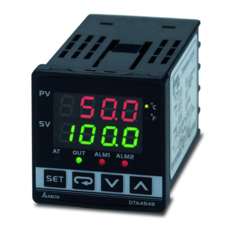
PV Display : to display the process value or parameter type.
SV Display : to display set point, manipulated variable or set
value of the parameter.
AT : flashes when the Auto-tuning operation is ON.
OUT : lights when the output is ON.
ALM1 / ALM2 : lights when Alarm 1 or Alarm 2 output is ON.
: Function key. Select the desired function mode and
confirm a setting value.
PV Display : Sıcaklık değeri ve parametre tipi görüntülenir.
SV Display : Sıcaklık set değeri, parametre değerleri ve
değişken çalışma değerleri görüntülenir.
AT : Auto-tuning çalışmasıON olduğu zaman flash yapar.
OUT : ÇıkışON olduğu zaman yanar.
ALM1 / ALM2 : ALM1 / ALM2 LED’leri Alarm 1 veya Alarm 2
çıkışlarıON olduğu zaman yanar.
: Fonksiyon tuşu. İstenilen fonksiyon modunu seç ve
ayarlanan bir değeri onayla.
