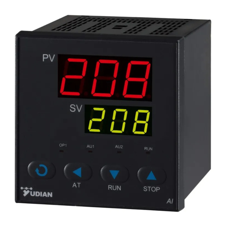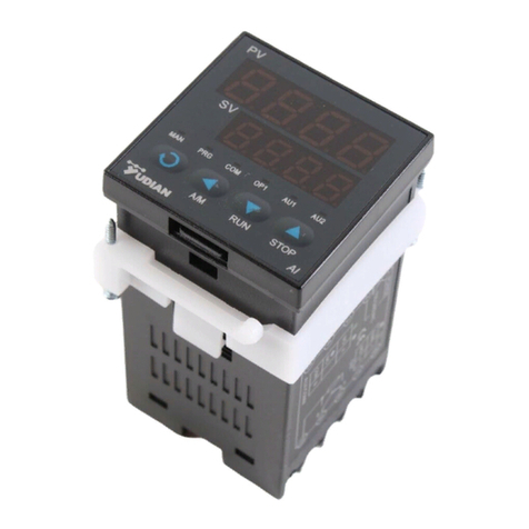
ARTIFICIAL INTELLIGENCE TEMPERATURE
CONTROLLER
AI-218/2181P User Manual
I. Main features
●Designed specially for plastic machinery, food process machinery, packaging
machinery and so on. Easy to learn and operate and lowest cost.
●Universal power supply 100~240VAC. 50/60Hz.C/F selectable.
●Freely choose input and output types, modularized ,prompt delivery,best service
after sale.
●Armed with AT and AI PID Intelligent control algorithm function.
●Burnt-proof design results in lower power consumption, higher reliability
and stability. Its power and I/O terminals pass 4KV/5KHz pulse crash proof
experiment.
●Qualifi ed with ISO9001, ISO14001 ,CE,and CQC, satisfying European RoHS
Standard.
II. Model Code Symbol
The type of AI-218 is made up of 4 parts:
AI-218 A G L0
Part 1 (Series) Part 2 (Size) Part 3 (Oupt) Part 4 (AUX)
Part 1 stands for Model series
AI-218, standard artifi cial intelligence temperature controller 0.3%FS±1℃accuracy.
0.1℃display resolution.
Based on AI-218, AI-2181 is with nPID function.
Part 2 stands for Front panel dimension
Size Front Panel
width×height
Cut Out
width×height
Depth Behind
Mounting Surface
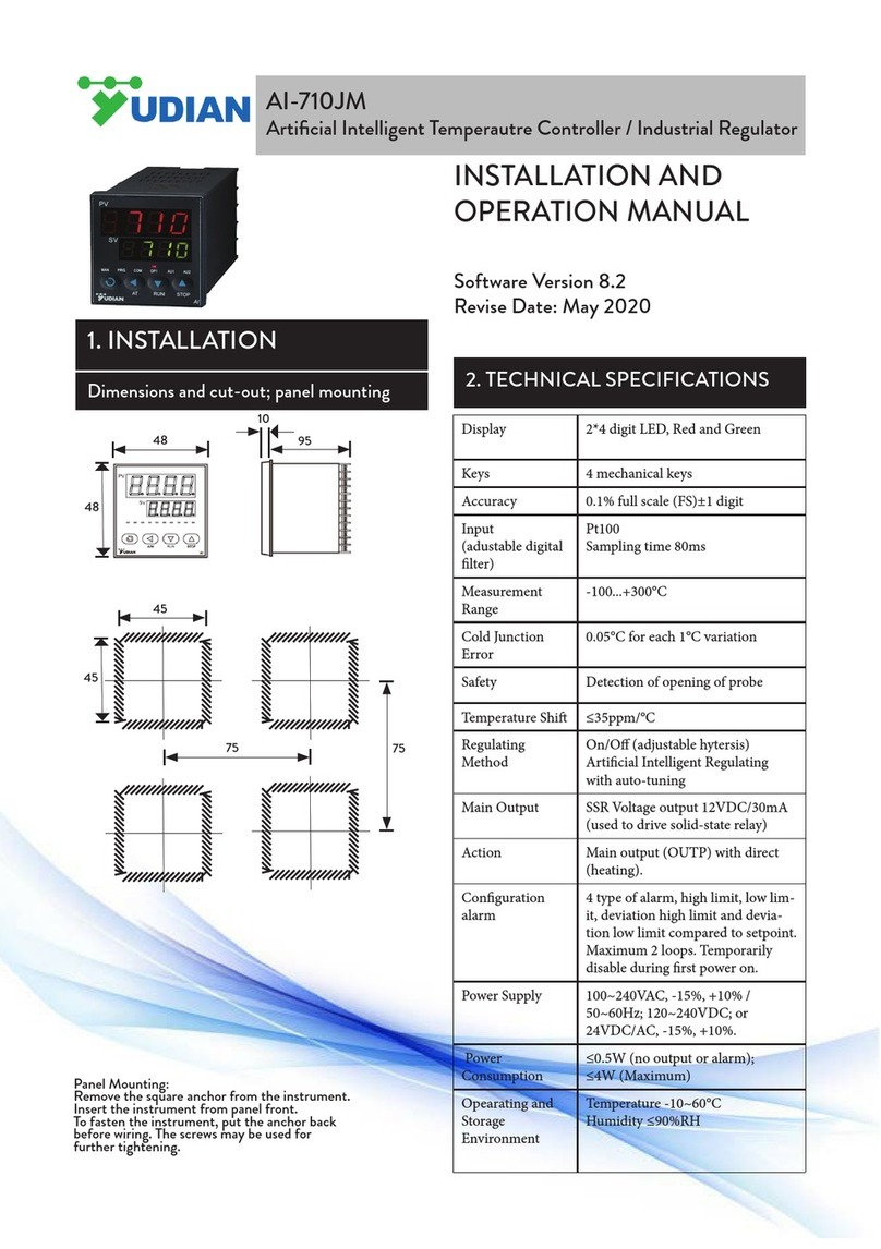
A96×96mm 92×92mm 100mm
A1 96×96mm 92×92mm 70mm
B 160×80mm 152×76mm 100mm
B1 160×80mm 152×76mm 70mm
C 80×160mm 76×152mm 100mm
C1 80×160mm 76×152mm 70mm
D 72×72mm 68×68mm 95mm
D1 48×48mm 45×45mm 78.5mm
D2 48×48mm 45×45mm 95mm
E48×96mm 45×92mm 100mm
E1 48×96mm 45×92mm 70mm
F96×48mm 92×45mm 100mm
F1 96×48mm 92×45mm 70mm
Part 3 indicates the module installed in OUTP socket.
L Relay contact output module (Capacity: 2A/250VAC, normal open)
G SSR voltage output module (30mA/5VDC)
Part 4 indicates Auxiliary alarm output
N (or none) no module installed
L0 Relay contact output module (Capacity: 2A/250VAC, normal open / normal close)
L2 Relay output module omron brand(1A/250VAC)
L5 Dual relay Output module (Capacity: 2A/250VAC, normal open, support AU1
and AU2 alarm output)
Remark: For D1-size instrument, OUTP (output module) is SSR mounted with
driving voltage 30mA/5VDC. AU1 is also selectable as relay alarm ouput
(NO+NC, 2A/250VAC). D1 is not in modular design.
III. Technical Specifi cation
1. Input type :
Thermocouple: K, E, J, N,Resistance temperature detector: Pt100
2. Instrument Input range:
K(0-1300℃), S(0-1700℃), R(0-1600℃), E(0-1000℃),J(0-1200℃),
N(0-1300℃),PT100(-200~+800℃)
3. Measurement accuracy: 0.3%FS±1℃/0.1℃
4. Control mode:
On-off control mode , or PID control with the function of parameter auto tuning.
5. Output: SSR 5VDC/30mA output ,Relay contact output ,open normally
6. Alarm function: High Alarm, Lower limit alarm,Deviation High Alarm.
7. Power supply voltage rating: 100-240VAC, -15%, +10% / 50-60Hz.
8. Power consumption: ≤3W.
9. Ambient temperature: -10~+60℃, Humidity: 0~90RH%
IV. Basic display status
1.Change given Set Value:
When powered on, it shows the basic display status, upper window displays real
process value (PV) while lower window displays the set value (SV). If the real
value overruns measure range(thermocouple breaks for example), upper window
will display "orAL" and the highest and lowest values, at this time, controller will
automatically stop controlling the output.
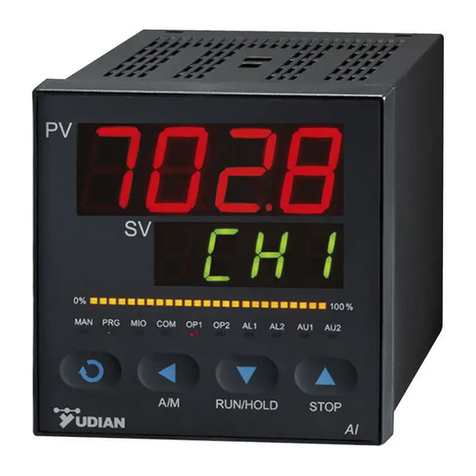
In controller's face, basically there are 6~10 LED lights,OP1,AU1,AU2,RUN which
respectively stand for output, fi rst alarm, second alarm, and working condition.
2.Change SV setting
In basal display status, if the parameter lock "Loc" isn't locked, we can set setpoint
(SV) by pressing
、
、
. Press
key to decrease the value,
key to increase the value, and
key to move to the digit expected to modify. Max
parameter of SPL and SPH, is limited to be 0~400C.
3 AI artifi cial intelligence control and auto tuning:
When AI artifi cial intelligence control method is chosen , the PID parameters can be
obtained by running auto-tuning. In basal display status, press
for 2 seconds,
the "At" parameter will appear. Press
to active the auto-tuning process. During
auto tuning, the instrument executes on-off control. After 2-3 times of on-off action,
the instrument will obtain the optimal control parameter value. If you want to escape
from auto tuning status, press and hold the
key for about 2 seconds until the "At"
parameter appear again. Change "At" from "on" to "oFF", press
to confi rm, then
the auto tuning process will be cancelled.
Note1 : AI-218 is with advanced PID, which makes it high accuracy.
Note2: If the setpoint is different, the parameters obtained from auto-tuning are
possible different. So you'd better set setpoint to an often-used value or middle
value first, and then start auto-tuning. Depending on the system, the auto-
tuning time can be from several seconds to several hours.
Note3: Setting of CHYS may have influence on AT.. The lower value of CHYS the
higher accuracy. But too low CHYS isn't advice, CHYS=2.0 is advice.
Note4: At the beginning after AT, the result maybe not table but it will get best result
after a time.
2 seconds auto tuning
V. Parameter Setting:
In basal display status, press and hold for about 2 seconds can access Field Parameter
Table. Pressing
can go to the next parameter; pressing
、
、
can
modify a parameter. Press and hold
can return to the preceding parameter. Press
(don't release) and then press
key simultaneously can escape from the
parameter table. The instrument will escape auomatically from the parameter table if
no key is pressed within 30 seconds. Setting Loc=808 and then press
can access
System Parameter Table.
+
2 seconds
2 seconds
Set
VI. Parameters and settings
Field parameter table (Press
and hold for 2 seconds to access)
Code Name Description Setting
Range
Default
value
HIAL High limit
alarm
Alarm on when PV (Process Value)
>HIA; alarm off when PV<HIA-AHY
Please refer to AOP description for
AU1,AU2.
-999~
+3000℃
3000℃
LoAL Lower limit
alarm
Alarm on when PV (Process Value)
<LoA; alarm off when PV>LoA-AHY
In case of electric short, it'll alarm after
it's second time lower than LoAL.
-999
HdA Deviation
high alarm
Alarm on when PV-SV>HdA; alarm
off when PV-SV<HdA-AHY
When HdAL is max, alarm function is
null.
3000℃
LdA Deviation low
alarm
Alarm on when PV-SV<LdA; alarm off
when PV-SV>HdA-AHY
When LdAL is minimum, alarm
function is null
-999
Loc Parameter
Lock
Loc=0: Allowed to modify parameters
and do AT
Loc=1: Allowed to modify parameters
but cannot AT
Loc=2: Allowed to modify parameters
and AT
Loc=4-255: NOT allowed to modify
parameters ecept Loc.
Loc=808, Set to 808 and press
,
allowed modify all parameters
0~255 0
Press can decrease the
value, press and keep pressing
it can make quick decrease
Press can increase the
value, press and keep pressing
it can make quick increase
Pressc can change the
targeted digit number of
value


