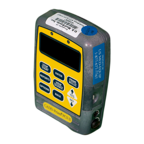
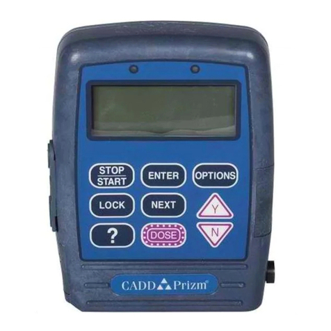
Deltec CADD-Prizm PCS II 6101 User manual

ii
PROOF (LR # 4559),2004-12-27 «4938-51C §0 Cover PCS II»,6.75″ × 9″
This manual concerns only the Deltec CADD-Prizm®PCS II (Pain Control
System) Model 6101 ambulatory infusion pump. This pump can be pro-
grammed to deliver medication at a constant rate and/or to allow delivery of a
bolus dose at a specified time interval. This manual is intended for clinician use
only. Do not permit patients to have access to this manual. Patient access to the
pump key should be restricted. The pump has three security levels designed to
limit patient access. Do not disclose the pump’s security codes or any other
information that would allow inappropriate access to programming and
operating functions.
The issue date of this Operator’s Manual is included for the clinician’s informa-
tion. In the event one year has elapsed between the issue date and product use,
the clinician should contact Smiths Medical MD, Inc. to see if a later revision
of this manual is available.
Technical Assistance
If you have comments or questions concerning the operation of the Deltec
CADD-Prizm®PCS II pump, please call the number given below. When calling,
please specify the pump’s software module. This information is located in the
pump’s start-up screen.
Our staff at Smiths Medical MD is available to help clinicians twenty-four
hours a day with the programming and operation of the Deltec CADD-Prizm®
PCS II infusion system.
U.S. Distribution: European Distribution:
Smiths Medical MD, Inc. Smiths Medical International Ltd.,
1265 Grey Fox Road WD24 4LG UK
St. Paul, Minnesota 55112 USA +44 (0)1923 246434
1-800-426-2448 (USA)
+1 651-628-7000
www.smiths-medical.com

iii
PROOF (LR # 4559),2004-12-27 «4938-51C §0 Cover PCS II»,6.75″ × 9″
Read this entire Operator’s Manual before operating the Deltec CADD-Prizm®
PCS II ambulatory infusion pump.
Failure to properly follow warnings, cautions, and instructions could result in
death or serious injury to the patient.
WARNINGS
• This Operator’s Manual should be used by clinicians only. Do not permit
patients to have access to this manual, as the information contained would
allow the patient complete access to all programming and operating
functions.
• To avoid explosion hazard, do not use the pump in the presence of flam-
mable anesthetics or explosive gases.
• For those patients who are likely to be adversely affected by unintended
operations and failures, including interrupted medication or fluid delivery
from the device, close supervision and provision for immediate corrective
action should be provided in order to assure minimum medication delivery
interruption. Pump failure will suspend medication delivery, and unin-
tended pump operations could lead to a variety of consequences for the
patient.
• If the pump is used to deliver life-sustaining medication, an additional
pump must be available, and close supervision and provision for immedi-
ate corrective action should be provided to assure minimum medication
delivery interruption in the event of a pump failure. Pump failure will
suspend medication delivery.
• The pump is not to be used for delivery of blood or cellular blood prod-
ucts, as blood and blood products will be damaged by the pumping
mechanism.
• If the pump is dropped or hit, inspect the pump for damage. Do not use a
pump that is damaged or is not functioning properly. Contact Customer
Service to return a pump for service.
• Use of a syringe with the CADD™Administration Set may result in UN-
DER-DELIVERY of medication. Syringe function can be adversely affected
by variations in plunger dimension and lubricity, which can result in
greater force required to move the syringe plunger. A syringe plunger will
lose lubrication as it ages and, as a result, the amount of under-delivery
will increase which could on occasion, be significant. Therefore, the type

iv
PROOF (LR # 4559),2004-12-27 «4938-51C §0 Cover PCS II»,6.75″ × 9″
of medication and delivery accuracy required must be considered when
using a syringe with the CADD®pump.
Clinicians must regularly compare the volume remaining in the syringe to
the pump’s displayed values such as RES VOL and GIVEN in order to
determine whether under-delivery of medication is occurring and if neces-
sary, take appropriate action.
• System delivery inaccuracies may occur as a result of back pressure or
fluid resistance, which depends upon drug viscosity, catheter size, and
extension set tubing (for example, microbore tubing). System delivery
inaccuracy may result in under- or overdelivery of medication.
• Do not administer drugs to the epidural space or subarachnoid space
unless the drug is indicated for those spaces.
• To prevent the infusion of drugs that are not indicated for epidural space
or subarachnoid space infusion, DO NOT use administration sets that
incorporate injection sites.
• If a Medication Cassette Reservoir, CADD™Extension Set or CADD™
Administration Set is used for epidural space or subarachnoid space drug
delivery, it is strongly recommended that it be clearly differentiated from
those used for other routes of infusion, for example, by color coding, or
other means of identification.
• When the Air Detector is not installed, or is installed but turned off, the
pump will not detect air in the fluid path. It is recommended that you
periodically inspect the fluid path and remove any air to prevent air
embolism.
• Follow the Instructions for Use provided with the Medication Cassette
Reservoir and CADD™Extension Set, or the CADD™Administration Set,
paying particular attention to all warnings and cautions associated with
their use.
• When the Upstream Occlusion Sensor is turned Off, the pump will not
detect occlusions upstream (between pump and fluid container). It is
recommended that you periodically inspect the fluid path for kinks, a
closed clamp, or other upstream obstructions. Upstream occlusions may
result in under- or nondelivery of medications.
• Do not disclose to the patient the pump’s security codes or any other
information that would allow the patient complete access to all program-
ming and operating functions.
To Purchase, Visit Avobus.com or call 1-800-674-3655

v
PROOF (LR # 4559),2004-12-27 «4938-51C §0 Cover PCS II»,6.75″ × 9″
• Ensure that the ±6% System Delivery Accuracy specification is taken into
account when programming the pump and/or filling the Medication
Cassette Reservoir. Failure to do so may result in medication in the reser-
voir becoming depleted sooner than expected.
• Do not use rechargeable NiCad or nickel metal hydride (NiMH) batteries.
Do not use carbon zinc (“heavy duty”) batteries. They do not provide
sufficient power for the pump to operate properly.
• Always have new batteries available for replacement. If power is lost,
nondelivery of drug will occur.
• There is no pump alarm to alert users that the battery has not been prop-
erly installed or has become dislodged. An improperly installed or dis-
lodged battery could result in loss of power and nondelivery of drug.
• If the pump is dropped or hit, the battery door may become broken or
damaged. Do not use the pump if the battery door is damaged because the
battery will not be properly secured; this may result in loss of power or
nondelivery of drug.
• After clearing the program, the pump will not go into the run mode
without programming a Continuous Rate or Demand Dose. The user may
be required to program other cleared delivery parameters.
• Setting this New Patient Marker option clears any internal Lockout time
and internal Delivery Limit. Once cleared, a Demand Dose could be
requested and delivered immediately upon starting the pump, and the full
volume could be delivered over the time period selected. You should
reprogram all settings related to Dose Lockout, Max Doses per Hour and
Delivery Limit, as appropriate for the particular patient.
• Attach the cassette properly. A detached or improperly attached cassette
could result in unregulated gravity infusion of medication from the fluid
container or a reflux of blood.
If you are using a Deltec administration set or medication cassette reser-
voir that does not have the flow stop feature (reorder number does not
start with 21-73xx): you must use a CADD™Extension Set with anti-
siphon valve or a CADD™Administration Set with either an integral or
add-on anti-siphon valve to protect against unregulated gravity infusion
that can result from an improperly attached cassette.
• When you enter a new Demand Dose Lockout time, any Demand Dose
Lockout time in effect will be cleared. A Demand Dose could be requested
and delivered immediately upon starting the pump, resulting in over-

vi
PROOF (LR # 4559),2004-12-27 «4938-51C §0 Cover PCS II»,6.75″ × 9″
delivery.
• When you enter a new Max Doses per Hour value, any lockout time in
effect will be cleared. A Demand Dose could be requested and delivered
immediately upon starting the pump, resulting in over-delivery.
• With the pump stopped and in LL0 ONLY: Entering a new Delivery Limit
will reset the delivery limit feature. When Delivery Limit is reset, any
delivery accumulated toward the Delivery Limit is automatically cleared.
This will allow delivery to begin as soon as the pump is started, which
may result in overdelivery.
• Per general rules of safe practice, always clamp tubing before removing the
cassette from the pump. Removing the cassette without closing the clamp
could potentially cause unregulated gravity infusion.
• Do not prime the fluid path with the tubing connected to a patient as this
could result in overdelivery of medication or air embolism.
• Ensure that the entire fluid path is free of all air bubbles before connecting
to the patient to prevent air embolism.
• Do not place the Remote Dose Cord where the button might accidentally
be pushed. Accidentally pushing the button may deliver an inadvertent
Demand Dose.
• Exercise care when using the Clinician Bolus function. Since there are no
limits on the frequency of delivering a bolus, and since the amount of the
bolus can be set as high as 20 ml (or the mg or mcg equivalent), you
should not permit the patient to become familiar with the procedure for
giving a Clinician Bolus.
• To prevent the patient from accessing the Clinician Bolus function, do not
let the patient know the Clinician Bolus code.
• If Demand Doses are currently locked out, changing the Date and/or Time
will cancel the lockout period. This will allow a Demand Dose to be
requested and delivered as soon as you restart the pump, and may result in
overdelivery.
• Changing the Date and/or Time will reset the Delivery Limit feature and
clear any delivery accumulated towards the Delivery Limit. This will allow
delivery to begin as soon as the pump is restarted, and may result in
overdelivery.

vii
PROOF (LR # 4559),2004-12-27 «4938-51C §0 Cover PCS II»,6.75″ × 9″
CAUTIONS
• To avoid damaging the pump’s electronics, do not operate the pump at
temperatures below +2°C (36°F) or above 40°C (104°F).
• To avoid damaging the pump’s electronics, do not store the pump at
temperatures below -20°C (-4°F) or above 60°C (140°F). Do not store the
pump with a Medication Cassette Reservoir or CADD™Administration
Set attached.
• To avoid damaging the pump’s electronics, do not expose the pump to
humidity levels below 10% or above 90% relative humidity.
• Do not store the pump for prolonged periods with the battery installed.
Battery leakage could damage the pump.
• If you are using a Medication Cassette Reservoir in which the medication
is frozen, thaw at room temperature only. Do not heat in a microwave
oven as this may damage the product and cause leakage.
• Do not use the Remote Dose Cord to pick up or carry the pump. Using the
cord in this manner could damage the pump or cord.
• To avoid damaging the connector or cord, do not use excessive force or
instruments, such as pliers, to remove the Remote Dose Cord from the
pump.
• Do not immerse the pump in cleaning fluid or water. Do not allow solu-
tion to soak into the pump, accumulate on the keypad, or enter the battery
compartment, Data In/Out jack, Power jack or Air Detector port area.
Moisture buildup inside the pump may damage the pump.
• Do not clean the pump with acetone, other plastic solvents, or abrasive
cleaners, as damage to the pump may occur.
• Do not expose the pump to therapeutic levels of ionizing radiation as
permanent damage to the pump’s electronic circuitry may occur. The best
procedure to follow is to remove the pump from the patient during thera-
peutic radiation sessions. If the pump must remain in the vicinity during a
therapy session, it should be shielded, and its ability to function properly
should be confirmed following treatment.
• Do not expose the pump directly to ultrasound, as permanent damage to
the pump’s electronic circuitry may occur.
• Do not use the pump in the vicinity of magnetic resonance imaging (MRI)
equipment as magnetic fields may adversely affect the operation of the
To Purchase, Visit Avobus.com or call 1-800-674-3655

viii
PROOF (LR # 4559),2004-12-27 «4938-51C §0 Cover PCS II»,6.75″ × 9″
pump. Remove the pump from the patient during MRI procedures and
keep it at a safe distance from magnetic energy.
• Use of this pump on patients monitored by electronic equipment may
cause artifactual interference. As with all electronic equipment, artifacts
which affect the performance of other equipment, such as ECG monitors,
can occur. The user should check the correct function of the equipment
prior to use.
• To avoid damaging the pump’s electronics, do not sterilize the pump.
• Use only Smiths Medical MD accessories as using other brands may
adversely affect the operation of the pump.
• Check appropriate medication stability for time and temperature to assure
stability with actual pump delivery conditions.

ix
PROOF (LR # 4559),2004-12-27 «4938-51C §0 Cover PCS II»,6.75″ × 9″
Operating
the Pump
Biomed
Toolbox
General
Description
Setup &
Programming Options Reference &
Troubleshooting
Table of Contents
WARNINGS iii
CAUTIONS vii
Section 1: General Description 1
1.1 Introduction ................................................................................. 1
1.2 Indications ................................................................................... 1
1.3 Epidural/Subarachnoid Administration ........................................ 1
1.3.1 Analgesics ........................................................................ 1
1.3.2 Anesthetics ..................................................................... 1
1.4 Symbols ......................................................................................... 3
1.5 Pump Diagram ............................................................................ 4
1.6 Description of the Keys, Display and Features ............................. 5
1.6.1 Indicator Lights ................................................................ 5
1.6.2 Display with backlighting ................................................ 5
1.6.3 Keypad ............................................................................ 5
1.6.4 Power jack ........................................................................ 6
1.6.5 Data In/Out jack .............................................................. 6
1.6.6 Air Detector Port Cover ................................................... 6
1.6.7 Air Detector accessory (optional) ..................................... 6
1.6.8 Cassette ........................................................................... 7
1.6.9 Polemount Bracket recess ................................................. 7
1.6.10 Battery compartment ........................................................ 7
1.6.11 Cassette latch ................................................................... 7
1.6.12 Cassette / Keypad lock ..................................................... 8
1.6.13 Other Features Not Shown .............................................. 8
1.7 The Main Screen .......................................................................... 9
1.8 Lock Levels .................................................................................. 10
1.8.1 AutoLock ......................................................................... 10
1.8.2 Security Codes ................................................................. 10
1.8.3 Customizing the Security Codes ........................................ 10
1.9 Lock Level Tables ........................................................................ 11
Section 2: Pump Setup and Programming 13
2.1 Installing the Battery .................................................................... 13
2.1.1 To install a battery ........................................................... 14
2.2 Power Up ..................................................................................... 15
2.2.1 If Biomed Toolbox is set to clear records and lockouts
in power up ...................................................................... 15
2.2.2 If Biomed Toolbox is set to clear program in power up..... 16

x
PROOF (LR # 4559),2004-12-27 «4938-51C §0 Cover PCS II»,6.75″ × 9″
2.3 Unlocking the Pump Program to LL0 .......................................... 18
2.3.1 To unlock the pump program using the Cassette / Keypad
Lock Key ......................................................................... 18
2.3.2 To unlock the pump using the keypad ............................... 18
2.4 Programming the Pump: General Instructions ............................. 19
2.4.1 Messages you may see during programming .................... 20
2.4.2 Before Beginning Programming ........................................ 20
2.5 REPORTS Key ............................................................................ 21
2.5.1 Dose Counters ................................................................. 21
2.5.2 Given ................................................................................ 22
2.5.3 Doses Hour By Hour ........................................................ 22
2.5.4 Patient Review ................................................................. 23
2.5.5 Pain Scale ......................................................................... 23
2.5.6 Pain Scale Log .................................................................. 24
2.5.7 Delivery Log .................................................................... 24
2.5.8 Event Log ........................................................................ 25
2.5.9 New Patient Marker ........................................................ 25
2.5.9.1 If Biomed Toolbox is set to clear records
and lockouts in Reports menu .......................... 25
2.5.9.2 If Biomed Toolbox is set to clear program
in Reports menu ................................................ 26
2.6 Delivery Methods ........................................................................ 28
2.7 Programming Screens .................................................................. 29
2.7.1 Units (if applicable) .......................................................... 30
2.7.2 Concentration .................................................................. 30
2.7.3 Continuous Rate .............................................................. 30
2.7.4 Demand Dose .................................................................. 31
2.7.5 Demand Dose Lockout .................................................... 31
2.7.6 Max Doses Per Hour ........................................................ 31
2.7.7 Set Delivery Limit ............................................................ 31
2.7.8 Reservoir Volume ............................................................ 32
2.7.9 Air Detector Status .......................................................... 32
2.8 Programming Example ................................................................ 33
2.9 Removing a Cassette .................................................................... 38
2.10 Attaching a Cassette .................................................................... 39
2.10.1 To attach the cassette to the pump ................................... 39
2.11 Priming the Tubing and Connecting to the Patient ........................ 42
2.12 Inserting the Tubing into the Air Detector ................................... 44
2.13 Locking the Pump Program for the Patient .................................. 45
2.13.1 To change the lock level when Autolock is not in use ........ 45
2.14 Remote Dose Cord ...................................................................... 47
To Purchase, Visit Avobus.com or call 1-800-674-3655

xi
PROOF (LR # 4559),2004-12-27 «4938-51C §0 Cover PCS II»,6.75″ × 9″
2.14.1 To attach the Remote Dose Cord ..................................... 47
2.14.2 To detach the Remote Dose Cord .................................... 47
2.15 Starting the Pump ........................................................................ 48
2.16 Adjusting Patient Delivery (Titration) .......................................... 49
2.16.1 Titrating while the pump is running ................................. 49
Section 3: Operating the Pump 51
3.1 Stopping the Pump ...................................................................... 51
3.1.1 To stop the pump ............................................................. 51
3.1.2 To turn pump indicators off .............................................. 51
3.2 Starting the Pump ........................................................................ 51
3.2.1 To start the pump ............................................................ 52
3.2.2 To turn pump indicators off .............................................. 52
3.3 Starting a Clinician Bolus ............................................................ 53
3.3.1 To start a Clinician Bolus ................................................. 53
3.4 Starting a Demand Dose .............................................................. 55
3.4.1 To start a Demand Dose .................................................. 55
3.5 Stopping a Demand Dose or Clinician Bolus ................................ 57
3.5.1 To stop a dose while the pump is running ........................ 57
3.6 Resetting the Reservoir Volume ................................................... 58
3.6.1 Resetting Reservoir Volume without changing
the cassette ........................................................................ 58
Section 4: Options 59
4.1 Overview: Accessing Options ...................................................... 59
4.1.1 To access Options ............................................................ 59
4.2 Lock Level ................................................................................... 60
4.2.1 To change Lock Level ...................................................... 60
4.3 Epidural Mode ............................................................................ 61
4.3.1 To turn Epidural Mode On or Off ................................... 62
4.4 Programming Units ...................................................................... 62
4.4.1 To change Units ................................................................ 62
4.5 Time ............................................................................................ 63
4.5.1 To change the Time of Day .............................................. 63
4.6 Date ............................................................................................. 64
4.6.1 To change the Date .......................................................... 64
4.7 Air Detector On/Off .................................................................... 65
4.7.1 To change the Air Detector Setting ................................... 66

xii
PROOF (LR # 4559),2004-12-27 «4938-51C §0 Cover PCS II»,6.75″ × 9″
Section 5: Biomed Toolbox 67
5.1 Overview: Accessing the Biomed Toolbox ................................... 67
5.1.1 To Access the Biomed Toolbox Menu ............................... 67
5.2 Custom Concentrations ................................................................ 68
5.3 Dosing Limits ................................................................................ 69
5.4 Delivery Limit .............................................................................. 70
5.5 Program Limits ............................................................................. 70
5.6 Maximum Delivery Rate ............................................................. 71
5.7 Key Beeps .................................................................................... 72
5.8 Res Vol Trip Point ........................................................................ 72
5.9 Res Vol Empty Alarm ................................................................... 73
5.10 Pump Stopped Alarm.................................................................... 73
5.11 Titration Limit ............................................................................. 74
5.12 AutoLock .................................................................................... 75
5.13 PM (Preventive Maintenance) Reminder ....................................... 76
5.14 Custom Lock Level Code ............................................................. 76
5.15 Custom Clinician Code ................................................................ 77
5.16 Units Selection .............................................................................. 78
5.17 Units Location ............................................................................. 78
5.18 Programming Units........................................................................ 79
5.19 Date Format ................................................................................. 80
5.20 Custom Main Display .................................................................. 80
5.21 Auto Review ................................................................................. 81
5.22 Custom Reports ........................................................................... 81
5.22.1 To access the Custom Reports Screens ............................. 82
5.22.1.1 Dose Counters ................................................ 82
5.22.1.2 Given ................................................................ 82
5.22.1.3 Doses Hour By Hour ........................................ 82
5.22.1.4 Patient Review ................................................. 82
5.22.1.5 Pain Scale ........................................................ 83
5.22.1.6 Pain Scale Log ................................................. 83
5.22.1.7 Delivery Log .................................................... 83
5.22.1.8 Event Log ........................................................ 83
5.22.1.9 New Patient Marker ........................................ 84
5.23 New Patient Marker Function ...................................................... 84
5.23.1 To view or change the New Patient Marker Function ........ 86
5.24 Upstream Sensor On/Off ............................................................. 87
5.25 Air Detector Requirement ............................................................ 88

xiii
PROOF (LR # 4559),2004-12-27 «4938-51C §0 Cover PCS II»,6.75″ × 9″
Section 6: Reference & Troubleshooting 89
6.1 Troubleshooting .......................................................................... 89
6.2 Alarms and Messages, Alphabetical List ....................................... 90
6.3 Cleaning the Pump and Accessories ............................................. 99
6.3.1 Cleaning the Battery Contacts .......................................... 100
6.4 Exposure to Radiation or Magnetic Resonance Imaging (MRI) ... 101
6.5 Continuous Rate Scroll Ranges .................................................... 102
6.6 Demand Dose, Clinician Bolus Scroll Ranges: Milliliters ............. 102
6.7 Demand Dose, Clinician Bolus Scroll Ranges: Milligrams ........... 103
6.8 Demand Dose, Clinician Bolus Scroll Ranges: Micrograms ......... 104
6.9 Military Time Conversion Chart ................................................. 105
6.10 Technical Description ................................................................... 106
6.10.1 Standards Used in Development of the Pump.................... 106
6.10.2 Specifications (Nominal) .................................................. 106
6.10.2.1 General Pump Specifications ............................ 106
6.10.2.2 Delivery Specifications ..................................... 109
6.10.2.3 Options Specifications ..................................... 110
6.10.2.4 Biomed Toolbox Specifications ........................ 110
6.10.3 Printed Reports ................................................................ 112
6.10.4 Screen Maps .................................................................... 113
6.11 Accuracy Test Results ................................................................... 115
6.12 Safety Features and Fault Detection .............................................. 117
6.13 Data Handling and Software Safety Features ................................ 117
6.14 Inspection Procedures ................................................................... 120
6.15 Testing Procedures ........................................................................ 121
6.16 Occlusion Pressure Range Tests .................................................... 127
6.17 Accuracy Tests .............................................................................. 130
Index .................................................................................................... 134
Limited Warranty ................................................................................. 137
To Purchase, Visit Avobus.com or call 1-800-674-3655

xiv
PROOF (LR # 4559),2004-12-27 «4938-51C §0 Cover PCS II»,6.75″ × 9″

General
Description
1
Section 1: General Description
Section 1: General Description
1.1 Introduction
The Deltec CADD-Prizm®PCS II (Pain Control System) ambulatory drug
delivery system provides measured drug therapy to patients in hospital or
outpatient settings. Therapy should always be overseen by a physician or a
certified, licensed healthcare professional. As appropriate, the patient should be
instructed in using the pump.
1.2 Indications
The Deltec CADD-Prizm®PCS II pump is indicated for intravenous, intra-arte-
rial, subcutaneous, intraperitoneal, epidural space, or subarachnoid space infu-
sion. The pump is intended for therapies that require a continuous rate of infu-
sion, patient-controlled demand doses, or both (such as patient-controlled anal-
gesia).
1.3 Epidural/Subarachnoid Administration
The selected drug must be used in accordance with the indications included in
the package insert accompanying the drug. Administration of any drug by this
pump is limited by any warnings, precautions, or contraindications in the drug
labeling.
1.3.1 Analgesics
Administration of analgesics to the epidural space is limited to use with ind-
welling catheters specifically indicated for either short- or long-term drug
delivery.
Administration of analgesics to the subarachnoid space is limited to use with
indwelling catheters specifically indicated for short-term drug delivery.
1.3.2 Anesthetics
Administration of anesthetics to the epidural space is limited to use with
indwelling catheters specifically indicated for short-term drug delivery.
WARNING: Do not administer drugs to the epidural space or subarachnoid
space unless the drug is indicated for administration to the those spaces. Drugs
not intended for epidural or subarachnoid space infusion could result in serious

2
General
Description
Section 1: General Description
patient injury or death.
To prevent the infusion of drugs that are not indicated for epidural space or
subarachnoid space infusion, DO NOT use administration sets that incorpo-
rate injection sites. The inadvertent use of injection sites for infusion of such
drugs may cause serious patient injury or death.
If a Medication Cassette Reservoir, CADD™Extension Set or CADD™Adminis-
tration Set is used for epidural space or subarachnoid space drug delivery, it is
strongly recommended that it be clearly differentiated from those used for
other routes of infusion, for example, by color coding, or other means of
identification. Drugs not intended for epidural or subarachnoid space infusion
could result in serious patient injury or death.
To Purchase, Visit Avobus.com or call 1-800-674-3655

General
Description
3
Section 1: General Description
1.4 Symbols
~Alternating Current
OAccessory Jack
!Attention, consult accompanying documents (read Instructions for Use)
KClass II Equipment
JType CF Equipment
ESplashproof - water splashed against pump housing will have no
harmful effects (see Cleaning the Pump and Accessories, Section 6,
for additional important information)
DDate of Manufacture
REF Catalog (reorder) number
SN Serial Number
CAUTION: Federal (USA) law restricts this device to sale by or on
the order of a physician.
Dispose of used batteries in an environmentally safe manner, and
according to any regulations which may apply

4
General
Description
Section 1: General Description
1.5 Pump Diagram
2000-03-07 D. Zurn
«Prizm Rear 3/4 (dark BW)»
Cassette (the part of the
Medication Cassette
Reservoir or CADD™
Administration Set that
attaches to the pump)
Polemount
Bracket Recess
Cassette / Keypad lock
Cassette latch
Battery
compartment
Rear View
⁄¤‹
Œ„ ´
ÅÍ Î
hkj
CADD-Prizm
®PCS II
Display
Power jack
Keypad
Data In/Out jack
Air Detector Port Cover
Air Detector
(optional)
Indicator Lights
Amber Green
Front View
®
®

General
Description
5
Section 1: General Description
1.6 Description of the Keys, Display and Features
1.6.1 Indicator Lights
When the pump is being powered the indicator light flashes.
Green: The green light flashes to indicate that the pump is running and
delivering fluid as programmed.
Amber: The amber light flashes when the pump is stopped or an alarm
condition exists. It stays on continuously when the pump is inoperable.
The display briefly describes the alarm condition.
If both lights are flashing, delivery is still occurring but an alert condition exists
(for example, a low battery). Look at the display for a brief description of the
alert condition.
1.6.2 Display with backlighting
The liquid crystal display (LCD) shows programming information and mes-
sages. Backlighting helps keep the display visible in low light. In this manual,
“display” is synonymous with display panel or LCD.
After a period in which no keys are pressed, the backlighting turns off and the
display blanks to save battery power (except during an alarm or when an
external power source is in use). Press any key to turn the display back on.
NOTE: If you press ⁄, the display will reappear with a message asking
if you wish to start or stop the pump; press ´or Î.
1.6.3 Keypad
The keys on the keypad are described below. A key beeps when pressed if it is
operable in the current lock level, provided Key Beeps have not been turned off
in the Biomed Toolbox.
⁄starts and stops pump delivery; silences alarms; used to access the
pump’s Indicators Off feature (see Section 3, Operating the Pump).
Œis used to view the pump’s Reports. Press the key to enter the Reports
screens, and press again to scroll through various reports screens.
Åis used to access the Options Menu, which contains such features as
Lock Levels, Epidural Mode, Time and Date. (See Section 4, Options.)
¤is used to enter, or save, a new value in the pump’s memory when pro-
gramming new doses or new pump settings. It is also used to select an item
from the Options Menu (Section 4) or Biomed Toolbox Menu (Section 5).
To Purchase, Visit Avobus.com or call 1-800-674-3655

6
General
Description
Section 1: General Description
„is used to view the programming screens without changing the setting or
value displayed. It is also used to return from the Options Menu to the
main screen, from the Reports menu to the main screen, or from the
Biomed Toolbox Menu to the Options Menu. (See the appropriate
sections of this manual.) It is also used to silence pump alarms.
Íallows the user to back up to the previous screen in programming,
Reports or Options. Íis not operable in the Biomed Toolbox.
‹has two functions. When the pump is stopped, pressing ‹accesses
the priming feature. When the pump is running, pressing ‹accesses
the Clinician Bolus feature. For more information on these features, see
the appropriate section of this manual.
´allows you to answer “yes” to a question on the pump’s display, “scroll
up” or increase a value (for example, a dose amount), or scroll through
items on a menu.
Îallows you to answer “no” to a question on the pump’s display, “scroll
down” or decrease a value, scroll through items on a menu, or cancel
printing.
1.6.4 Power jack
You may plug a CADD™External Power Source (EPS) system power pack or an
AC Adapter into the Power jack as an alternate source of power.
1.6.5 Data In/Out jack
The Data In/Out jack is used for attaching the following accessories:
•Interface Cable for printing reports
•Remote Dose Cord
•Interface Cable/Null Modem Cable for communications
For more information on the Remote Dose Cord, see the appropriate section in
this manual. For more information on printing or communications, see the
instructions for use provided with the interface cable.
1.6.6 Air Detector Port Cover
This encloses the Air Detector port when the Air Detector is not attached.
1.6.7 Air Detector accessory (optional)
The Air Detector attaches to the pump in the area shown in the diagram. If air is
detected in the part of the tubing that passes through the Air Detector, an alarm
Table of contents
Other Deltec Medical Equipment manuals
Popular Medical Equipment manuals by other brands

Teeter Hang Ups
Teeter Hang Ups ComforTrak Series Assembly instructions
Carestream
Carestream CS 8100 3D user guide
Dräger
Dräger Oxylog VE300 quick start guide
MYLAN
MYLAN Sirdupla quick start guide
Sirona
Sirona DAC UNIVERSAL Operating instruction
Johnson & Johnson
Johnson & Johnson DePuy Synthes Battery Power Line II Instructions for use

