Deltec CADD-Prizm PCSII 6101 User manual
32
T
E
C
H
N
I
C
A
L
M
A
N
U
A
L
C
A
D
D
-
P
r
i
z
m
®
P
C
S
I
I
A
M
B
U
L
A
T
O
R
Y
I
N
F
U
S
I
O
N
P
U
M
P
MODEL 6101
Deltec

31
For detailed instructions, specifications, warnings, warranties and additional information on operat-
ing CADD®pumps, please refer to the Operator’s Manual supplied with the product. If you have
additional comments or questions concerning the operation of CADD®pumps, please call this num-
ber: (800) 426-2448. Our staff is available to help you 24 hours a day with the programming and
operation of CADD®pump infusion systems.
The issue date of this Technical Manual is included for the user’s information. In the event one year
has elapsed between the issue date and product use, the user should contact Deltec, Inc. to see if a
later revision of this manual is available.
Issue Date: July 2003

33
Table of Contents
1. Introduction ............................................. 1
Limited Warranty ........................................... 1
Exposure to Radiation or Magnetic Resonance
Imaging (MRI) ............................................... 1
2. CADD-Prizm®PCS II Pump ..................... 2
Delivery Modes .............................................. 2
Specifications (Nominal) ................................ 5
3. Batteries ................................................... 8
Battery Compatibility ..................................... 8
DURACELL®Alkaline Battery Life ................ 8
ULTRALIFE®Lithium Battery Life ................ 8
4. Construction .......................................... 10
5. Theory of Operation .............................. 11
Keyboard Circuitry ...................................... 11
Data Memory EEPROM .............................. 11
Battery Backed RAM ................................... 11
Time Base Circuitry ...................................... 11
LCD Circuitry .............................................. 11
LED Status Indicators .................................. 12
Flash PROM Technology ............................. 12
Gate Array Circuitry .................................... 12
Audible Alarm Circuitry ............................... 12
Watchdog Timer Circuit .............................. 12
Motor Driver/Motor Watchdog Circuit ....... 12
Power Circuitry ............................................ 13
Voltage Reference Circuit ............................. 13
Pumping Mechanism .................................... 13
Pumping Characteristics ............................... 14
Air Detector ................................................. 15
Upstream Occlusion Sensor .......................... 15
6. Safety Features and Fault Detection ....... 16
Hardware Safety Features ............................ 16
Watchdog Timer Circuit .............................. 16
Motor Driver/Motor Watchdog Circuit ....... 17
Cassette ‘Type’ Sensor Circuit ...................... 17
Latch/Lock Sensor Circuit ............................ 17
Voltage Detector Circuit .............................. 17
Software Safety Features .............................. 18
7. Hardware and Software Fault Detection .. 19
Overview ...................................................... 19
Order of Error Code Events ......................... 19
8. Cleaning and Inspection Procedures ....... 20
Inspection Recommendation ........................ 20
Cleaning ....................................................... 20
Visual Inspection .......................................... 20
Mechanical Inspection .................................. 21
9. Testing Procedures ................................. 22
Functional Testing ........................................ 22
Air Detector Test (if Applicable)................... 25
Occlusion Tests ............................................ 25
Accuracy Testing .......................................... 27
Cleaning and Functional Testing Checklist ... 30

1
1 Introduction
The Technical Manual is intended to provide
a basic, but limited, understanding of the me-
chanical and electrical operation of the Deltec
CADD-Prizm®PCS II Computerized Ambulatory
Drug Delivery pump to persons familiar with this
device. The CADD-Prizm®PCS II Operator’s
Manual should be used in conjunction with this
publication for complete information.
This manual also outlines cleaning and func-
tional testing procedures that can be performed
on the CADD-Prizm®PCS II pump.
This technical manual is applicable to the
CADD-Prizm®PCS II pump only.
IMPORTANT NOTICE:
CADD-Prizm®PCS II pump operations and
safety features are based on a microcomputer
design. Inadequate servicing or tampering with
the safety features of the pump may seriously
affect performance and safety.
For that reason, ALL SERVICING AND
REPAIR OF THE CADD-Prizm®PCS II
PUMP MUST BE PERFORMED BY DELTEC
OR ITS AUTHORIZED AGENTS.
The manufacturer’s warranty agreement shall
become null and void if the pump is not used
in accordance with the Operator’s Manual and
Instructions for Use for the pump accessories;
or, the pump is serviced by persons other than
Deltec or those authorized by Deltec.
Limited Warranty
The limited warranty associated with the
CADD-Prizm®PCS II pump can be found in the
product literature supplied with the product
when originally purchased, which is incorpo-
rated herein by reference. DELTEC SPECIFI-
CALLY DISCLAIMS ANY OTHER WAR-
RANTY, WHETHER EXPRESS, IMPLIED OR
STATUTORY, INCLUDING, WITHOUT
LIMITATION, ANY IMPLIED WARRANTY
OF MERCHANTABILITY OR FITNESS FOR
USE. Deltec further disclaims responsibility for
the suitability of the system for a particular
medical treatment or for any medical compli-
cations resulting from the use of the system.
The manufacturer shall not be responsible for
any incidental damages or consequential
damages to property, loss of profits, or loss of
use caused by any defect or malfunction of the
system.
If you wish to receive additional information
about the extent of the warranty on these prod-
ucts, please contact your Deltec representative or
call Customer Service at (800) 426-2448.
All recommendations, information and litera-
ture supplied by Deltec with respect to the
CADD®product line are believed to be accu-
rate and reliable, but do not constitute warran-
ties. No agent, representative, or employee of
Deltec has authority to bind Deltec to any
representation or warranty, expressed or
implied.
Exposure to Radiation or Magnetic
Resonance Imaging (MRI)
CAUTIONS:
(1) The pump SHOULD NOT BE
DIRECTLY IRRADIATED by therapeutic
levels of ionizing radiation because of the
risk of permanent damage to the pump’s
electronic circuitry. The best procedure to
follow is to remove the pump from the
patient during therapeutic radiation sessions
or diagnostic levels of radiographic and
fluoroscopic radiation. If the pump must
remain in the vicinity during a diagnostic or
therapy session, it should be shielded, and
its ability to function properly should be
confirmed following treatment.
(2) Magnetic fields produced by magnetic
resonance imaging (MRI) equipment may
adversely affect the operation of the pump.
Remove the pump from the patient during
MRI procedures and keep it at a safe
distance from magnetic energy.

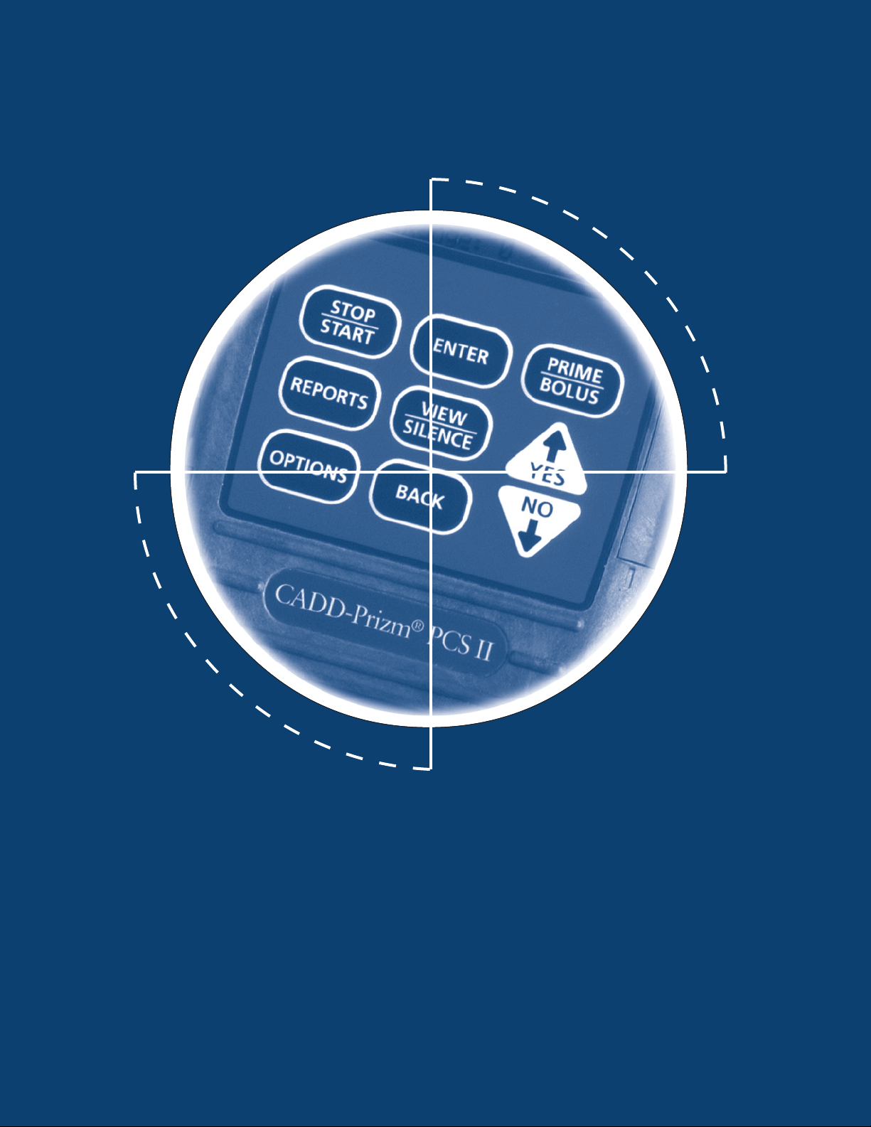
2
2 CADD-Prizm
®
Pump
Figure 1. Front and back views of the CADD-Prizm®PCS II pump.
Rear View
Delivery Modes
The Deltec CADD-Prizm®PCS II pump
provides measured drug therapy to patients.
CADD-Prizm®PCS II pumps are indicated for
intravenous, intra-arterial, subcutaneous,
intraperitoneal, epidural space or subarachnoid
space infusion. Epidural administration is
limited to short-term infusion of anesthetics
and either long- or short-term infusion of
analgesics. Subarachnoid administration is
limited to short-term infusion of analgesics.
Upstream Occlusion Sensor
⁄¤‹
Œ„´
ÅÍÎ
hkj
CADD-Prizm
®
PCSII
Display
Power jack
Keypad
Data In/Out jack
Air Detector
Port Cover
Air Detector
(optional)
Indicator Lights
Amber Green
2000-03-07 D. Zurn
«Prizm Rear 3/4 (dark BW)»
Cassette
Polemount
Bracket Recess
Cassette lock
Cassette latch
Battery
compartment
Front View

3
Figure 2. PCA mode delivery profile.
Clinician Bolus
(used here as a loading dose)
Demand Doses
Continuous Rate
Time
Dosage
PCA Delivery Profile
The PCA (patient-controlled analgesia) delivery
mode is used for therapies that require a
continuous rate of infusion, patient-controlled
demand doses or both, such as patient-
controlled analgesia.

4
Table 1. PCA delivery mode: continuous rate scroll ranges.
Units Starting Increment Maximum
Milliliters 0.10 0.10 30.00
Milligrams & 10% of Mg only: Values between 0.01 and 0.5: 0.01 Concentration
Micrograms concentration Mcg only: Values between 0.1 and 0.5: 0.1 x 30
Values between 0.5 and 100: 0.1
Values between 100 and 1000: 1.0
Values greater than 1000: 10.0
Continuous Rate Scroll Ranges
Concentration
mg/ml
Demand Dose
increment max.
Clinician Bolus
increment max.
Milligrams
0.1 0.01 0.99 0.01 2
0.2 0.02 1.98 0.02 4
0.3 0.03 2.97 0.03 6
0.4 0.04 3.96 0.04 8
0.5 0.05 4.95 0.05 10
10.05 9.9 0.05 20
20.10 19.8 0.10 40
30.15 29.7 0.15 60
40.20 39.6 0.20 80
50.25 49.5 0.25 100
60.30 59.4 0.30 120
70.35 69.3 0.35 140
80.40 79.2 0.40 160
90.45 89.1 0.45 180
10 0.50 99.0 0.50 200
11 0.55 108.9 0.55 220
12 0.60 118.8 0.60 240
13 0.65 128.7 0.65 260
14 0.70 138.6 0.70 280
15 0.75 148.5 0.75 300
20 1.00 198.0 1.00 400
25 1.25 247.5 1.25 500
30 1.50 297.0 1.50 600
35 1.75 346.5 1.75 700
40 2.00 396.0 2.00 800
45 2.25 445.5 2.25 900
50 2.50 495.0 2.50 1000
55 2.75 544.5 2.75 1100
60 3.00 594.0 3.00 1200
65 3.25 643.5 3.25 1300
70 3.50 693.0 3.50 1400
75 3.75 742.5 3.75 1500
80 4.00 792.0 4.00 1600
85 4.25 841.5 4.25 1700
90 4.50 891.0 4.50 1800
95 4.75 940.5 4.75 1900
100 5.00 990.0 5.00 2000
Table 3. Demand dose, clinician bolus scroll ranges, micrograms
Demand Dose Clinician Bolus
increment max. increment max.
0.05 9.9* 0.05 20
Milliliters
Table 4. PCA delivery mode: Demand dose, clinician
bolus scroll ranges, milliliters
*The maximum Demand Dose is 20 with software revision E or
higher.
Table 2. Demand dose, clinician bolus scroll ranges,
milligrams
Demand Dose
increment max.
Clinician Bolus
increment max.
Micrograms
Concentration
mcg/ml
10.05 9.9 0.05 20
20.10 19.8 0.10 40
30.15 29.7 0.15 60
40.20 39.6 0.20 80
50.25 49.5 0.25 100
60.30 59.4 0.30 120
70.35 69.3 0.35 140
80.40 79.2 0.40 160
90.45 89.1 0.45 180
10 0.50 99.0 0.50 200
11 0.55 108.9 0.55 220
12 0.60 118.8 0.60 240
13 0.65 128.7 0.65 260
14 0.70 138.6 0.70 280
15 0.75 148.5 0.75 300
20 1.00 198.0 1.00 400
25 1.25 247.5 1.25 500
30 1.50 297.0 1.50 600
35 1.75 346.5 1.75 700
40 2.00 396.0 2.00 800
45 2.25 445.5 2.25 900
50 2.50 495.0 2.50 1000
55 2.75 544.5 2.75 1100
60 3.00 594.0 3.00 1200
65 3.25 643.5 3.25 1300
70 3.50 693.0 3.50 1400
75 3.75 742.5 3.75 1500
80 4.00 792.0 4.00 1600
85 4.25 841.5 4.25 1700
90 4.50 891.0 4.50 1800
95 4.75 940.5 4.75 1900
100 5.00 990.0 5.00 2000
200 10.00 1980.0 10.00 4000
300 15.00 2970.0 15.00 6000
400 20.00 3960.0 20.00 8000
500 25.00 4950.0 25.00 10000

5
Specifications (Nominal)
General Pump Specifications
Resolution
Medication Cassette Reservoir or CADD®
Administration Set, 0.050 ml per pump
stroke nominal
Size
4.4 cm x 10.4 cm x 14.1 cm [1.7 in. x 4.1
in. x 5.6 in.] excluding cassette or other
accessories
Weight
568 g [20 oz.] including 9 volt battery and
empty 100 ml Medication Cassette Reser-
voir, excluding other accessories
Pump Alarms
Low battery power; depleted battery
power; external power source low, faulty,
depleted; pump stopped; pump fault; low
reservoir volume; high delivery pressure;
air in line; Air Detector faulty or detached
(only with the use of the optional Air
Detector); Air Detector Port Cover de-
tached; delivery too slow; key stuck;
cassette detached or unlocked; print fail-
ure, epidural cassette not used.
Bolus Volume at Occlusion Alarm Pressure
0.050 ml resolution administration sets/
Medication Cassette Reservoirs: <0.25 ml
Power Sources
9 volt alkaline or lithium battery such as
DURACELL®Alkaline MN 1604 or
ULTRALIFE®Lithium U9VL; CADD®
External Power Source (EPS) Power Pack
reorder number 21-3801; AC Adapter.
The expected life of a 9 volt battery is 12
hours at 100 ml/hour, or approximately 5
days at 10 ml/day (nominal). This estimate
is based on laboratory tests conducted at
room temperature using a new battery.
Actual battery life will vary depending on
the brand of battery, shelf life, temperature
conditions, delivery rate, and frequency of
screen display, backlighting and printing. It
is recommended that a new 9 volt battery be
kept available for replacement if necessary.
An internal battery powers the clock.
When it is depleted, it cannot reliably
* If programmed to be part of pump programming screens in Biomed Toolbox.
maintain the clock time. This battery must
be replaced by the manufacturer. The
internal battery has an expected life of 5
years.
System Operating Temperature
+2°C to 40°C (36°F to 104°F)
System Storage Temperature
-20°C to 60°C (-4°F to 140°F)
Power Pack Charging Temperature
+10°C to 35°C (50°F to 95°F)
System DeliveryAccuracy
±6% (nominal)
System Definition
System is defined as a CADD-Prizm®pump
with an attached Medication Cassette
Reservoir and CADD®Extension Set with
integral anti-siphon valve, or an attached
CADD®Administration Set with integral
or add-on anti-siphon valve.
Delivery Specifications
Reservoir Volume
1 to 9999 or Not In Use; programmable in
1 ml increments, displayed in 0.1 ml
increments.
Default: 1 ml
Units*
Milliliters (ml), milligrams (mg), micro-
grams (mcg).
Default: milligrams
Concentration
Mg/ml:
0.1 to 0.5 mg/ml in increments of 0.1
1 to 15 mg/ml in increments of 1 mg/ml
20 to 100 mg/ml in increments of 5 mg/ml
Default: 100 mg/ml
Mcg/ml:
1 to 15 mcg/ml in increments of 1 mcg/ml
15 to 95 mcg/ml in increments of 5 mcg/ml
100 to 500 mcg/ml in increments of 100
mcg/ml. Default: 500 mcg/ml
Continuous Rate
0to30 ml/hr (or the mg or mcg equivalent).
Default: 0 mg/hr (See Table 1 for Scroll
ranges)

6
Demand Dose
0 to 9.9 ml*
Delivery rate (Continuous Rate + Demand
Dose): programmable from 40 to 125 ml/hr.
Default: 0 ml (See Table 2, 3 & 4 for Scroll
ranges)
*The Maximum Demand Dose is 20 with
software revision E or higher.
Demand Dose Lockout
5 minutes to 24 hours in the following
increments:
•1minute for values between 1 and 20
minutes
•5minutes between 20 minutes and 24
hours
Default: 5 min
Set Delivery Limit
0.5 ml to 1000 ml (or the mg or mcg
equivalent), or “No Limit”:
0.01 from 0.01 to 0.1
0.1 from 0.1 to 100
1.0 from 100 to 1000
10.0 from 1000 to 10000
100.0 from 10000 to 100000
1000.0 from 100000 and up
Default: 0.5 ml or mcg or mg equivalent
Given
0 to 99999.99 in 0.01 unit increments.
Clinician Bolus
0.1 ml to 20.00 ml (or mg or mcg equivalent)
Delivery rate (Continuous Rate + Clinician
Bolus): 125 ml/hr nominal (See tables 2, 3
& 4 for Scroll ranges)
High Pressure Alarm
18 ±9 psi [1.24 ±0.62 bar]
Air Detector Alarm
Single bubble greater than 0.100 ml
Options Specifications
Lock Level
LL0, LL1, LL2. Default: LL2
Epidural Mode
On or Off. Default: Off
Units*
Milliliters (ml), milligrams (mg), micro-
grams (mcg).
Default: milligrams
Time
00:00 to 23:59
Air Detector
Turned On or Turned Off. Default: On
Biomed Toolbox Specifications
Custom Concentrations
All individual mg or mcg concentration
settings may be enabled or disabled (at
least one concentration must be enabled).
Default: All On
Program Limits*
Maximum program limits may be pro-
grammed for Demand Dose, Continuous
Rate, and Clinician Bolus.
Default: maximum program limits.
Dosing Limit*
Delivery Limit, a Maximum Doses per
Hour, or neither. Default: Neither
Key Beeps
On or Off. Default: On
Res Vol Trip Point
1 to 999 ml in increments of 1 ml, or
“Standard.” Default: Standard
Res Vol Empty Alarm*
Single or Insistent alarm. Default: Single
Pump Stopped Alarm*
Beep or Two-tone alarm. Default: Beep
AutoLock
Not In Use, LL1 Key/Code, LL2 Key/Code,
LL1 No Key or LL2 No Key. Default: Not
In Use
PM (Preventive Maintenance) Reminder
1 to 24 months in 1 month increments, or
“Not In Use.” Default: Not In Use
Custom Lock Level Code
001 to 899 (excluding preset code) in
increments of 1. Default: 061
Units Selection*
Program units to appear in the Program-
ming Units screens. Default: All Program-
ming Units
Units Location
Options, Program or Biomed Toolbox.
Default: Programming screens
* If programmed to be part of Options settings in the Biomed Toolbox.

7
Defaulting the Lock Level Code & Clinician
Bolus Code
The standard Lock Level Code (061) can be
changed to a customized code using the
Biomed Toolbox Custom Lock Code feature.
See the Operator’s Manual supplied with the
pump for instructions on customizing the Lock
Level Code. If it becomes necessary to change a
customized code back to the standard Lock
Level Code, do the following:
1. Press the OPTIONS key until the Lock Level
screen appears.
2. Press the ENTER key twice.
3. Scroll to 911.
4. Press the OPTIONS key.
Compatible Reservoirs and
Administration Sets
•50-ml or 100-ml Medication Cassette reser-
voir, used with the CADD®extension set
with anti-siphon valve.
•CADD®administration set with integral
anti-siphon valve, with or without bag spike
(allows use of flexible plastic bag or sterile
vial with injector)
•CADD®administration set with add on anti-
siphon valve and bag spike (allows for
gravity priming before attaching the add on
anti-siphon valve)
Remote Dose Cord
Deltec provides a Remote Dose Cord for the
PCA delivery mode. The push button switch is
a Single Pole Double Throw (SPDT). When the
Remote Dose Cord is attached to the pump,
the patient may press the Remote Dose button
to receive a Demand Dose. The clinician may
use the Remote Dose button to deliver a
clinician bolus. For easy access, the Remote
Dose cord may be fastened to the patient’s
clothing or bedsheet with the attached clip.
NOTE:
To detach the Remote Dose cord from the
pump, grasp the Remote Dose cord
connector and pull back using a straight,
steady motion. Do not twist or turn the
connector, or use any instrument to remove it.
For additional specifications refer to the
Operator’s Manual provided with the product.
Date Format
US Standard (mm/dd/yy) or European
Standard (dd/mm/yy). Default: U.S. Standard
Custom Main Display
Display:
•Res Vol or Continuous Rate
•Power Source Always or Low 9 volt
battery only
Default: Res Vol and Low 9V
Auto Review*
Select the automatic program review feature
during the pump’s power-up sequence.
Default: On
•Dose Counters (0 to 999 Given and/or
Attempted). Default: On
•Given. Default: On
•Doses Hour By Hour (up to 48 hours in
increments of 1 hour). Default: Off
•Patient Review. Default: Off
• Pain Scale (subjective pain scale rating of
0 to 10 in increments of 1). Default: On
•Pain Scale Log (0 to 500 entries).
Default: On
•Delivery Log (0 to 500 events). Default: Off
•Event Log (0 to 500 events). Default: Off
•New Patient Marker. Default: On
New Patient Marker*
Reports/No Clear, Power-up/No Clear,
Reports/Clear, Power-up/Clear
Default: Reports/No Clear
Air Detector Required
Required or Not Required. Default: Not
Required
Note: The CADD-DIPLOMAT®PC Communications System batch programming mode
must be used to change a customized code back to the standard lock level code with
CADD-Prizm®PCS II pumps with software revision E or higher.

8
Battery Compatibility
Recommended Batteries
Nine-volt alkaline or lithium batteries are
recommended for use in the CADD-Prizm®
pump. Carbon-zinc, mercury, nickel-cadmium,
or zinc-air 9-volt batteries should not be used.
Battery Life
The CADD-Prizm®pump has been designed to
provide optimal battery life. The expected
battery life in the CADD-Prizm®pump depends
on the following factors:
•Programmed delivery rate
•Operating temperatures
•Frequency of display backlighting
•Frequency of printing
•Battery type and brand
•Battery age
DURACELL®Alkaline Battery Life
The following tables may be used to predict
typical alkaline battery life at different delivery
rates when an alkaline battery is used in the
CADD-Prizm®pump. As expected, battery life
decreases as the delivery rate increases. These
tables are based on laboratory tests using fresh
DURACELL®alkaline batteries in CADD-Prizm®
pumps while the pumps were operating at room
temperature.
Actual battery life may be significantly shorter
depending on the operating temperature and
the storage conditions of the battery.
Battery life is shortened significantly at very
low operating temperatures. For example, at
0°C (32°F), an alkaline battery will yield
approximately 30% of its normal capacity.
Alkaline batteries do not need to be stored in a
refrigerator. After four years of storage at 21°C
3Batteries
(70°F), an alkaline battery retains approxi-
mately 86% of its original capacity. Battery life
will be shorter if the battery is stored above
room temperature. An alkaline battery stored at
43°C (110°F) will be down to approximately
80% of its capacity within one year.
Recommended storage conditions are 10°C to
25°C (50°F to 77°F) with no more than 65%
relative humidity noncondensing.
The following tables are based on laboratory
tests conducted at room temperature using fresh
DURACELL®alkaline batteries and a CADD®
administration set. Actual battery life will vary
depending on the brand of battery, battery shelf
life and temperature conditions.
ULTRALIFE®Lithium Battery Life
The following tables may be used to predict
typical lithium battery life at different delivery
rates when a lithium battery is used in the
CADD-Prizm®pump. As expected, battery life
decreases as the delivery rate increases. These
tables are based on laboratory tests using fresh
ULTRALIFE®lithium batteries in CADD-Prizm®
pumps while the pumps were operating at room
temperature.
Actual battery life may be significantly shorter
depending on the operating temperature and
the storage conditions of the battery. Lithium
battery life is dependent upon the temperature
and relative humidity of storage. Recommended
storage conditions are less than 20°C (68°F)
with a desiccant to ensure less than 10%
relative humidity.
The following tables are based on laboratory
tests conducted at room temperature using fresh
ULTRALIFE®lithium batteries and a CADD®
administration set. Actual battery life depends
upon the brand of battery selected, the
particular battery selected, battery shelf life,
and temperature conditions. Deltec’s testing
indicates a large variability in battery life.

9
Rate Life Volume
0.4 ml/hr 120 hrs 48 ml
10 ml/hr 86 hrs 860 ml
30 ml/hr 37 hrs 1110 ml
50 ml/hr 26 hrs 1300 ml
100 ml/hr 13 hrs 1300 ml
200 ml/hr 14 hrs 2800 ml
350 ml/hr 7 hrs 2450 ml
Rate Life Volume
0.4 ml/hr 212 hrs 85 ml
10 ml/hr 161 hrs 1610 ml
30 ml/hr 79 hrs 2370 ml
50 ml/hr 60 hrs 3000 ml
100 ml/hr 30 hrs 3000 ml
200 ml/hr 32 hrs 6400 ml
350 ml/hr 17 hrs 5950 ml
Table 4. 9-volt Alkaline-type batteries used with the CADD-Prizm®pump.
Table 5. 9-volt Lithium-type batteries used with the CADD-Prizm®pump.
Table 6. EPS System used with the CADD-Prizm®pump.
Continuous and PCA Delivery Battery Life (Max Delivery Rate PCA Mode 30 ml/hr)
Note: Results are without air detector.
Rate Life Volume
100 ml/hr 64 hrs 6400 ml
200 ml/hr 67 hrs 13400 ml
350 ml/hr 39 hrs 13650 ml

10
4Construction
The pump’s housing is made of a special high
impact plastic designed to reduce interference
from electromagnetic fields and to dissipate
electrostatic discharge. It is composed of two
sections: the base and cover housing. The
pump housing is sealed to ensure that the
pump is water resistant. The battery compart-
ment is not water resistant.
NOTE:
The CADD-Prizm®ambulatory infusion
pump is water resistant, but not waterproof.
The battery compartment is accessed through a
removable door on the side of the base hous-
ing. Within the battery compartment is space
for the battery and the two battery contacts.
The Medication Cassette reservoir or the
administration set is attached to the bottom of
the pump by inserting the two hooks on the
cassette into the mating hinge pins on the pump.
The pump and the reservoir or the administra-
tion set are then placed in an upright position
on a firm, flat surface. The reservoir or the
administration set can be latched in place by
inserting a coin in the slot on the pump’s
latching button, pushing the button in, and
turning the button one-quarter turn counter-
clockwise. The reservoir or the administration
set is locked into place by inserting a key into
the pump’s lock and turning the lock one-
quarter turn counterclockwise.
NOTE:
The cassette lock must be unlocked before
attempting to unlatch the disposable.
NOTE:
The Medication Cassette reservoir and the
administration set are intended for single
use only.
The keyboard, located on the front housing, is
composed of nine membrane switches and is
sealed against moisture. All of the keys contain
domes to provide a tactile feel when the key is
pressed. The keyboard keys are sensed by the
pump’s microprocessor.
The custom Liquid Crystal Display (LCD), also
located on the front housing, shows the pump
status and programmed settings. The dot
matrix display consists of 21 character col-
umns with 4 rows of characters, and is selected
by the pump’s microprocessor according to
status conditions and keyboard entries.
The microprocessor and other circuitry which
control the pump are located on two printed
circuit boards. The microprocessor board
contains the Central Processing Unit (CPU)
and its associated circuitry, motor driver
circuitry, and other miscellaneous circuitry.
The LCD board contains the Liquid Crystal
Display with its associated circuitry, and the
backlight module with its associated circuitry.
The pumping mechanism subassembly contains
the motor, gear train, camshaft, valves,
expulsor, sensing disk, infrared light source,
infrared detector, occlusion sensor, cassette
sensors, lock and latch. Via the motor driver
circuitry, the pump’s microprocessor controls
motor rotation.
Two external port connectors are utilized for
communication and external power input. One
of these connectors, the data in/out jack, is
used for attachment of the Remote Dose cord.
This enables the patient to use the Remote
Dose cord to begin a Demand Dose.
This jack can also be connected via an inter-
face cable to an external PC to view reports or
to a printer to print reports. The second port is
for external power connection. This port, the
power jack, can receive input from either an
AC adapter or the External Power Source
rechargeable power pack.
Connections between the printed circuit boards
are designed for ease of manufacturing and
serviceability. The keyboard is connected to the
microprocessor board via a flex circuit tail.
Flexible circuitry and discrete wires connect
the pumping mechanism, motor, and sensors to
the printed circuit boards.

11
5Theory of Operation
Keyboard Circuitry
The CADD-Prizm®PCS II pump is controlled
by a microprocessor. The actions of the micro-
processor are controlled by a program, which
is contained in the memory.
Commands are issued to the microprocessor
from the user via the nine keys on the key-
board and the Remote Dose cord. The keys on
the keyboard feed individually into the Gate
Array on the microprocessor board. A key
closure applies a ground to the associated
input of the Gate Array. Key debounce cir-
cuitry resident in the Gate Array provides a
clean output signal to the microprocessor for
the duration of the key closure. The micropro-
cessor reads keyboard status by accessing
special memory locations in the Gate Array.
The Remote Dose button consists of an SPDT
switch with its own dedicated input to the
microprocessor circuitry. The switch has a
common input line and two output signal
lines. The two signal lines are complementary
such that one line is always logic high and the
other is always low. When the Remote Dose
button is pressed, both signal lines change to the
alternate logic state. This redundancy prevents a
single line failure from starting a dose delivery.
Data Memory EEPROM
Many settings of the pump’s delivery and
record keeping parameters are stored by the
microprocessor in an Electrically Erasable
Programmable Read Only Memory
(EEPROM). Data to and from the memory is
presented serially. Whenever the microproces-
sor uses data from the EEPROM, the data is
checked for validity.
Battery Backed RAM
Additional settings of the pump’s delivery and
record keeping parameters are stored in a
battery backed Random Access Memory
(RAM). Battery backup is provided by two
printed circuit board-mounted lithium batter-
ies. These batteries are designed to provide a
minimum of five years of memory retention
during normal pump usage. Whenever the
microprocessor uses data from the RAM, the
data is checked for validity.
Time Base Circuitry
An accurate 3.6864 MHz timebase is provided
by a quartz crystal. The 3.6864 MHz signal is
connected to the microprocessor, where it is
frequency-divided to access the program
memory at a cycle rate of 921 kHz.
In addition, an accurate 32.768 kHz timebase
is provided by a second quartz crystal. The
32.768 kHz signal is used for the real time
clock.
LCD Circuitry
The high-impedance, low-power, special
drive signals for the liquid crystal display are
provided by the LCD-drivers. Each alpha or
numeric character on the LCD is formed by
darkening combinations of dots. Commands
to display dots are issued via data bus
commands to the LCD-drivers by the
microprocessor.
The LCD circuit also contains a power supply
which provides bias voltage to the LCD panel.
This voltage controls the relative brightness of
the characters. Additional circuitry allows the
microprocessor to disable the LCD when not
in use in order to conserve battery power.
A two brightness level LCD backlight is
provided to improve LCD viewing under low
light conditions. When the microprocessor
enables the LCD, it also enables the low
brightness backlight. Low brightness is used to
conserve battery power. If the AC adapter is
connected, the microprocessor will enable the
high brightness backlight since this does not
consume power from the battery.
The backlight automatically shuts off when the
LCD is turned off.

12
LED Status Indicators
An amber and a green Light Emitting Diode
(LED) are provided under the pump’s front
panel overlay to provide pump status to the
user. Under software control, the LEDs can
either flash at a low duty cycle or be on con-
tinuously. A flashing indicator typically indi-
cates a normal mode of operation and a steady
“on” indicator typically indicates a fault
condition.
Flash PROM Technology
Program memory for the pump is stored in
Flash Programmable Read Only Memory
(Flash PROM). This type of memory allows
modification of the contents without physically
removing the device from the circuit board.
Under certain circumstances, the program can
also be downloaded through the I/O port on
the side of the pump. Several layers of redun-
dancy in the programming system prevent
accidental erasing or modification of the
PROM.
Gate Array Circuitry
The Gate Array contains circuitry which
controls memory address decoding, keyboard
debounce, Light Emitting Diode (LED) indica-
tor status, LCD command buffering, Battery
Backed RAM interface, and miscellaneous
signal line buffering functions.
Audible Alarm Circuitry
Audible alarm circuitry consists of a piezo
electric disk and independent oscillator. The
disk flexes or bends in resonance with the
output of the oscillator. The piezo disk is
mounted to the pump housing to enhance
sound level. The oscillator which drives the
piezo disk is capable of providing two driving
frequencies. The low frequency is in the range
of 700 to 1500 Hz and the high frequency is in
the range of 1600 to 2500 Hz. The micropro-
cessor controls the audible alarm via control
lines from the Gate Array. When the micropro-
cessor selects both the low and high frequency
control lines, the audible alarm enters a warble
mode where it oscillates between the low and
high frequency sound at a rate of 0.8 and 2
Hz. Low battery voltage detection and watch-
dog timer circuitry also have the ability to
enable the audible alarm via the Gate Array.
Watchdog Timer Circuit
Watchdog timer circuitry is provided to moni-
tor the status of the microprocessor and
disable the motor and enable the audible alarm
if the microprocessor fails to function properly.
The microprocessor must strobe the watchdog
circuit at least once every second in order to
prevent the watchdog from performing its reset
function. The reset output from the watchdog
circuit is a pulse output. This acts to “jump
start” the microprocessor. This unique feature
allows the microprocessor to test the watchdog
circuit on every power-up. By setting a flag in
memory and not strobing the watchdog, the
microprocessor can force a watchdog time-out.
After being reset, the microprocessor checks
the status flag to see if this was a time-out test.
If so, the microprocessor continues normal
power-up activities. If the reset occurred when
the microprocessor was not expecting it, the
microprocessor traps the event, sounds the
audible alarm and displays an error message
on the LCD.
Motor Driver/Motor Watchdog
Circuit
Motor drive circuitry is composed of a series of
power FET transistors, passive components,
and two voltage comparators. Built into the
motor drive circuitry is an RC timer which
times how long the motor runs each time it is
turned on. If the motor runs for more than an
average of 4 seconds, the circuit will time out
and disable the motor. A unique feature of this
circuit is that control lines to and from the
microprocessor circuit allow the microproces-
sor to perform a complete functional test of the
motor drive circuit without running the motor.
The microprocessor performs this test function
every several minutes to assure its continued
functionality. An input from the watchdog
circuit prevents motor operation if the watch-
dog timer expires.
Rotation of the motor is sensed by the micro-
processor via an infrared-sensitive photo

13
detector. An infrared light source is mounted
so that its light beam illuminates the infrared
detector. An opaque flag is mounted concentri-
cally to the camshaft and rotates with it be-
tween the infrared light source and detector.
When the flag interrupts the light beam, the
output of the detector is sensed by the micro-
processor via an input port bit. Power to the
infrared LED light source is controlled by the
motor driver circuit and is off when the motor
is not running to conserve battery life.
In the microprocessor software, multiple
checks are made on motion of the camshaft.
When the motor is commanded to start, the
infrared sensor must show that half a revolu-
tion has occurred within five seconds and that
the motor has stopped when half a rotation
was completed. In addition, no camshaft
rotation can take place when the motor has
not been commanded to run.
Power Circuitry
Power for the pump is normally supplied by a
9-volt alkaline battery, 9-volt lithium battery,
or AC adapter. These types of batteries have a
fairly low internal resistance over their dis-
charge range, which will keep power supply
noise low. Other types of batteries, such as
carbon-zinc, exhibit high internal resistance,
especially near depletion. A voltage drop
across the internal resistance occurs when
current is drawn by the motor during pump
activations. This current is demanded in short
pulses when the motor is first turned on and
generates large spikes in the battery voltage.
This noise can cause the low battery detection
circuit to shut down the pump.
The motor driver circuit power is taken di-
rectly from the battery, but the microprocessor
and its associated circuitry requires closely
regulated and filtered 5-volt power which is
supplied from the micropower voltage regula-
tor. This regulator will supply 5-volt power
until its input voltage is approximately 5.3
volts. After that point, the output of the
regulator will follow the input voltage down.
Voltage Reference Circuit
A voltage reference circuit provides a constant
DC voltage to the microprocessor Analog to
Digital Converter (ADC). By reading this input
and comparing the value to a predetermined
range, the microprocessor can validate the
accuracy of the 5-volt power supply. Variations
in the 5-volt supply left undetected can result
in inaccuracy in the low battery alarm set
points and variations in other calculated values.
Table 12. CADD-Prizm®pump low battery conditions.
Voltage CADD®Pump Status
Trip Point*
>7.0V No alarm
6.4–7.0V* Transition to low battery
condition; battery low
message appears; 3 beeps
every 5 min.†
6.0–6.6V* Transition to depleted
battery condition; battery
depleted message appears;
continuous alarm††
5.25–5.95V Hardware reset occurs.
Pump continues to indicate
depleted battery condition.
*Voltage ranges are due to component
tolerances. Actual trip values are guaran-
teed to be non-overlapping.
† The pump emits 3 beeps every 5 minutes, and the
message “9 Volt Battery Low” appears on the pump’s
display, indicating that the battery power is low, but the
pump is operable.
†† The pump emits a continuous, variable-tone alarm,
and the message “9 Volt Battery Depleted” appears on
the display, the battery power is too low to operate the
pump, and pump operation has stopped.
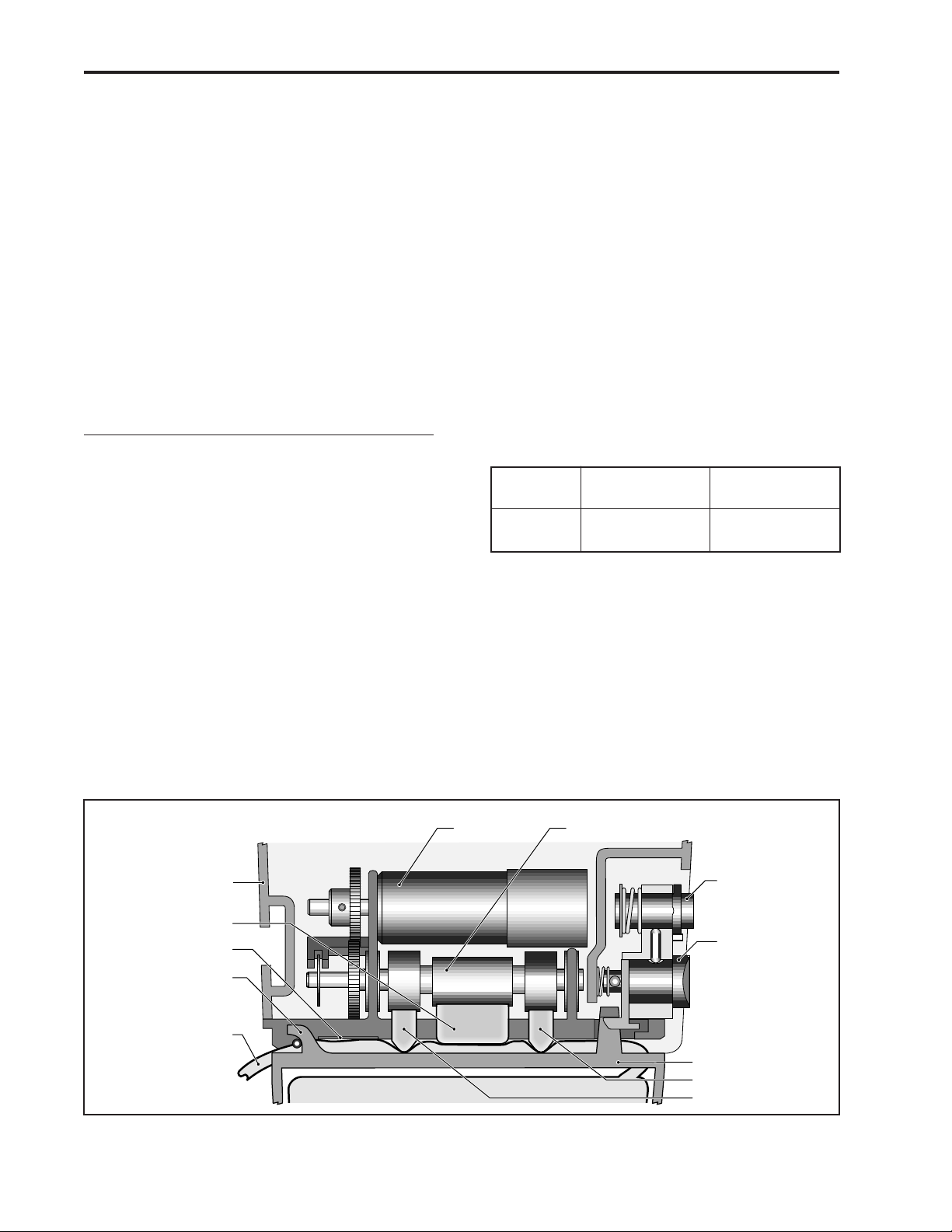
Pumping Mechanism
The pumping mechanism is linear peristaltic
with two active valves. Pumping occurs when
the expulsor presses on the reservoir pump
tubing in sequence with the inlet and outlet
valves. At rest, the outlet valve is pressing
down fully on the tubing and the expulsor and
inlet valve are retracted. (See Figure 7.)
14
When the microprocessor commands the mecha-
nism to pump, the camshaft begins to rotate,
thus controlling the following pump cycle:
1. The inlet valve closes.
2. In synchrony with the expulsor moving
down to compress the tubing, the outlet
valve opens, expelling 0.050 ml of fluid.
3. The outlet valve closes.
4. The inlet valve opens as the expulsor is
retracted, causing fluid from the reservoir to
again fill the pump tubing segment.
5. The camshaft rotation stops after half a
revolution and the cycle is completed.
Pumping Characteristics
If the fluid path to the patient becomes blocked,
the pump tubing will expand as pumping
occurs. When there has been an amount of
inflation corresponding to 124 ±62 kPa
(1.24 ±0.62 bar, 18 ±9 psi), the occlusion
analog sensor trips, whereupon the micropro-
cessor stops the pump mechanism and issues
visual and audible alarms. Thus the maximum
pressure which can be developed is 186 kPa
(1.86 bar, 27 psi).
To deliver the amount of drug specified by the
parameter settings, the pump’s microprocessor
causes the pump mechanism to deliver 0.05 ml
fluid “pulses” timed according to the desired
rate. At rates higher than 3 ml/hr, 2 pulses in
succession will be given. Thus, to deliver 20
ml/hr, for example, the microprocessor solves
these equations:
Mechanism activations per hr
=20 ml per hr/0.1 ml per activation
=20/0.1
=200
Time (seconds) between activations
=3600 sec per hr/number of activations per hr
=3600/200
=18
Rate Volume
(ml/hr) Resolution (ml)
Cassette or 0 - 3 0.050
Admin Set 3.1 - 125 0.100
The microprocessor uses its timer circuits to
accurately time the 18 seconds (in this ex-
ample) between mechanism activations. The
timebase accuracy is ultimately determined by
the 3.6864 MHz quartz crystal oscillator.
Figure 7. A simulated pumping mechanism in a CADD-Prizm®pump.
Lock Button
Latch Button
Pressure Plate
Inlet Valve
Outlet Valve
Pump Tubing
Cassette Hinge
Occlusion Sensor
Expulsor
Pump Housing
Camshaft
Motor

15
Air Detector
The air detector is designed to detect air in the
outlet tubing fluid path. The air detector is
detachable if not needed. The CADD-Prizm®
pump automatically detects the presence of the
air detector and will automatically turn the
sensor on when powered up in LL0.
When the optional air detector is installed, the
Biomed Toolbox feature allows the air detector
to be “required” or “not required.” When the air
detector is not required, it can be “turned on” or
“turned off” using the Options menu. When the
air detector is required, the option for turning
the air detector on or off will not be available.
When the air detector is turned on, the pump
will detect the presence of air in the outlet tubing
fluid path. If the air detector settings are “not
required” and “turned off,” it will default to
“turned on” each time the pump powers up in
Lock Level 0.
The air detector is compatible with all of the
reservoirs and sets indicated for use with the
CADD-Prizm®pump, and all pump accessories.
It is powered directly from the CADD-Prizm®
pump and no additional power is required.
Specifications
The air detector will alarm when it senses a
single air bubble greater than 100 microliters
(0.1 milliliters.)
Construction
The air detector housing is made of a special
high impact plastic and has a metalized film
coating on the inside surface to reduce interfer-
ence from electromagnetic fields. The air detector
is composed of a single base compartment with a
detachable door. It is sealed against the pump
housing to ensure the overall assembly is water
resistant. The air detector is mounted to the
pump housing with two screws, and electrically
connected with a ten pin connector.
Theory of Operation
The air detector consists of sensor electronics
and two ultrasonic transducers positioned on
opposite sides of the tubing. One transducer acts
as an acoustic transmitter and the other as an
acoustic receiver. Air detection occurs when air
in the fluid path causes a reduction in the signal
level to the receiver. When the signal is inter-
rupted for a preset length of time, the sensing
circuitry sends a signal to the microprocessor
indicating air in the fluid path. To maximize the
reliability of the system and to reduce false
alarms, the transmitted signal is swept over a
frequency range. This accommodates varying
resonance frequencies of the transducer and
reduces sensitivity to tubing tolerances and other
mechanical variations.
Upstream Occlusion Sensor
Theory of Operation
The upstream occlusion sensor is a strain
gauge device capable of detecting pressure
changes in the disposable tubing set. This is
accomplished by using a loading ball or sphere
located on the bottom of the pump. This
loading ball contacts the pump tubing when a
tubing set is attached to the pump. Under
normal operation, the pump tube pushes
outward and applies a specified force on the
sensor. When an upstream occlusion is present,
the upstream tubing collapses pulling away
from the sensor reducing the force on the
sensor. It is this change of the force that indi-
cates an upstream occlusion.

16
6Safety Features and
Fault Detection
Hardware Safety Features
Key hardware safety features include a watch-
dog timer circuit, motor driver and motor
watchdog circuits, cassette ‘type’ sensor circuit,
latch/lock sensor circuit, and a voltage detector
circuit. Each safety circuit performs a unique
function to insure the overall safety of the
device. (See Figure 8.)
Watchdog Timer Circuit
The microprocessor must send an appropriate
signal to the watchdog circuit at least once per
second. If the microprocessor does not, the
watchdog circuit will time out and shut down
the pump controller.
Watchdog timer circuitry is provided to monitor
the status of the microprocessor and disable
the motor and enable the audible alarm if the
microprocessor fails to function properly. The
microprocessor must strobe the watchdog
circuit at least once every second in order to
prevent the watchdog from performing its reset
function. The reset output from the watchdog
circuit is a pulse output. This acts to “jump
start” the microprocessor. This unique feature
allows the microprocessor to test the watchdog
circuit on every power-up. By setting a flag in
memory and not strobing the watchdog, the
microprocessor can force a watchdog time-out.
After being reset, the microprocessor checks
the status flag to see if this was a time-out test.
If so, the microprocessor continues normal
power-up activities. If the reset occurred when
the microprocessor was not expecting it, the
microprocessor traps the event, sounds the
audible alarm and displays an error message
on the LCD.
Figure 8. CADD-Prizm®pump hardware block diagram.
PROGRAM
MEMORY
MB
DATA
MEMORY
MB
LCD DISPLAY VOLTAGE
REFERENCE
MOTOR
DRIVER
WATCHDOG
REAL-TIME
CLOCK
CPU/IO/
GATE ARRAY
KEYBOARD
MOTOR
WATCHDOG
VOLTAGE
DETECTOR
SENSORS
AUDIBLE
ALARM

17
Motor Driver/Motor Watchdog Circuit
Motor drive circuitry is composed of a series of
power FET transistors, passive components,
and two voltage comparators. Built into the
motor drive circuitry is an RC timer which
times how long the motor runs each time it is
turned on. If the motor runs for more than an
average of 4 seconds, the circuit will time out
and disable the motor. A unique feature of this
circuit is that control lines to and from the
microprocessor circuit allow the microprocessor
to perform a complete functional test of the
motor drive circuit without running the motor.
The microprocessor performs this test function
every several minutes to assure its continued
functionality. An input from the watchdog
circuit prevents motor operation if the watch-
dog timer expires.
Cassette ‘Type’ Sensor Circuit
The cassette ‘Type’ sensor system consists of
three pins protruding from the button of the
pump mechanism that interface to the attached
administration set and associated circuitry.
Each type of administration set designed to
work with the CADD-Prizm®pump contains a
unique ‘code’ programmed into the set via
nubs molded into the plastic. When a set is
latched to the pump, the nubs press against the
pins in the pump mechanism in a pattern
unique to that set type. Optical detectors and
electronic circuitry on the circuit board encode
this pattern and report the information to the
microprocessor. This feature allows automatic
rate selection dependent on the type of set
attached. This system also acts as a safety
feature to detect a damaged or detached set.
If, during operation, the microprocessor
detects all pins extended, the pump will enable
audible and visual alarms and stop delivery.
Redundancy in the pattern prevents single fault
failures from causing over or under delivery of
fluid. Additional circuitry allows these sensors
to be turned on and off by the microprocessor
to conserve battery power. Additionally, control
of sensor power allows the microprocessor to
test the sensor inputs in both the powered and
unpowered states, thus allowing detection of
sensor fault conditions. Care should be taken
not to damage these sensor pins.
Latch/Lock Sensor Circuit
Latch and Lock sensors allow the microproces-
sor to detect the positions of the latch and lock
buttons. This prevents attempted fluid delivery
when the set is not correctly latched to the
pump. In addition, it allows the microprocessor
to stop fluid delivery and enable audible and
visual alarms if the set is unlatched during fluid
delivery. Opposing infrared transmitters and
receivers on both the latch and lock buttons
allow the microprocessor to detect their open
and closed positions. Additional circuitry
allows these sensors to be turned on and off by
the microprocessor to conserve battery power.
Additionally, control of sensor power allows
the microprocessor to test the sensor inputs in
both the powered and unpowered states, thus
allowing detection of sensor fault conditions.
Voltage Detector Circuit
Low voltage detection is performed by part of
the watchdog circuit and by the microprocessor
via software. Three low voltage levels are
detected. The first two levels are detected by
software and the third by hardware. The first
level to be reached is the Low Battery Warning
threshold which occurs when the battery
voltage decays to a nominal value of 6.8 volts.
An Analog to Digital Converter (ADC) built
into the microprocessor allows the micropro-
cessor, via software, to monitor the battery
voltage. At the Low Battery Warning thresh-
old, the microprocessor enables a periodic
series of beeps and displays a low battery
warning message on the LCD. As the battery
voltage reaches a nominal value of 6.3 volts,
the software disables delivery, places a battery
depleted message on the LCD, and enables a
constant two-tone audible alarm. When the
battery voltage decays to a nominal value of
5.6 volts, a hardware reset circuit is triggered
which places the microprocessor in reset. This
prevents ambiguous microprocessor operation
when the battery voltage continues to decay.
The hardware reset continues until the battery
is completely discharged or until it is removed.
Once the pump controller goes into low
battery shutdown, only replacing the old
battery with a fresh one will clear the condition.
Table of contents
Other Deltec Medical Equipment manuals


Popular Medical Equipment manuals by other brands

Drive DeVilbiss
Drive DeVilbiss 1025 Series Instruction guide

CeraGem
CeraGem MASTER V4 user manual

Stryker
Stryker ComfortGel 2850-000-016 Operation manual

Invacare
Invacare Propad Revolve V user manual

St. Jude Medical
St. Jude Medical Angio-Seal Evolution Instructions for use

Beurer
Beurer DM 20 Instructions for use


